manuals.online logo
Brands
  1. Home
  2. •
  3. Brands
  4. •
  5. Trane
  6. •
  7. Accessories
  8. •
  9. Trane ZZSENSAL0300AA User manual

Trane ZZSENSAL0300AA User manual

ZZSENSAL0300AA/BAYSEN30ATEMPA
Indoor Remote Sensor/Outdoor Remote Sensor
INSTALLATION INSTRUCTIONS
FAILURE TO READ AND FOLLOW ALL INSTRUCTIONS CAREFULLY
BEFORE INSTALLING OR OPERATING THIS CONTROL COULD CAUSE
PERSONAL INJURY AND/OR PROPERTY DAMAGE.
SPECIFICATIONS
Forapplicationswherethewirerunisshort(100ft.or
less)shieldedcablemaynotberequiredprovidedthe
wires are not routed parallel to or across other wires
carrying electrical power.To reduce electrical inter-
ferenceorinductancefromotherelectrical wiring or
devicesuse shielded cable and keepRemoteSensor
wireruns separatefrom thermostatwiring. Remote
sensors cannot be used with systems where power
interruptions are part of normal system operation.
Operating Range: (based on thermostat range)
ZZSENSAL0300AA Indoor Model: 40 to 99°F
BAYSEN30ATEMPA Outdoor Model: -40 to 140°F
Operating Humidity Range: 0 to 90% RH
(non-condensing)
Maximum Distance fromThermostat: 300 feet
Recommended Wire: 18 or 20 gauge,
3-conductor shielded cable
Color: Classic White
Dimension: 2-1/8" x 3-1/2" x 3/4"
Outdoor Remote includes 12 ft. of outdoor
probe lead
ZZSENSAL0300AA
INDOOR REMOTE SENSOR
BAYSEN30ATEMPA
OUTDOOR REMOTE SENSOR
Interior Mounting Base
Outdoor Probe
CONTENTS
Specications................................................ 1
Installation .................................................... 2
Wiring Diagram...............................................3
Conguration.................................................3
Troubleshoong ...............................................4
CAUTION
!
To prevent electrical shock and/or equipment
damage,disconnectelectricpowertosystemat
mainfuseorcircuitbreakerboxuntilinstallation
is complete.
WARNING
!
Do not use on circuits exceeding specied
voltage. Higher voltage will damage control
and could cause shock or re hazard.
Do not short out terminals on gas valve or
primary control to test. Short or incorrect
wiringwilldamagethermostat and couldcause
personal injury and/or property damage.
Pub No. 18-HD86D1-1
Part No. 37-7772001
August 2018
2
INSTALLATION
INDOOR SENSOR
SELECT SENSOR LOCATION
Proper location insures that the remote sensor
will provide a comfortable home or building
temperature. Observe the following general rules
when selecting a location:
1. The remote sensor can be located a maximum
of 300 feet from the thermostat.
2. Locate sensor about 5 . above the room oor
level.
3. Install sensor on a partitioning wall, not on an
outside wall.
4. Never expose sensor to direct light from lamps,
sun, replaces or any temperature radiating
equipment.
5. Avoid locations close to windows, adjoining
outside walls, or doors that lead outside.
6. Avoid locations close to air registers or in the
direct path of air from them.
7. Makesure there are no pipes orductworkinthat
part of the wall chosen for the sensor location.
8. Never locate sensor in a room that is normally
warmer or cooler than the rest of the home
(such as the kitchen) or building.
9. Avoid locations with poor air circulation, such
as behind doors or in alcoves.
10. Inthehome,thelivingor diningroomisnormally
a good location, provided there is no cooking
range or refrigerator on opposite side of wall.
OUTDOOR SENSOR
SELECT SENSOR LOCATION
Proper location insures that the remote sensor will
provide a correct outdoor temperature reading.
Observe the following general rules when selecting
a location:
1. The interior mounting base can be located a
maximum of 300 feet from the thermostat.
2. Install the interior mounting base within 12 .
of the intended outdoor probe location.
3. Never install the outdoor probe where it
will be exposed to direct light from lamps,
sun, replaces or any temperature radiating
equipment.
4. Make sure there are no pipes or ductwork in the
wall chosen for the base location.
5. Outdoor temperature measurement requires
installing the probe outdoors. Good probe
locations would be under a bay window or
overhang, out of direct sunlight. Direct sun
exposure will aect sensed temperature. Install
probe with spacer to obtain a more accurate
temperature.
Mounting
Surface
Spacer
6. Although connected to the probe wire for
outdoor temperature sensing, the interior
mounting base must be placed indoors.
Therefore, the interior mounting base must
be installed near the perimeter of the building,
so that the probe wire can be run through to
the outside of the structure and placed in the
selected (shaded) location. The outdoor probe
wire is 12 feet long (and should not be cut or
spliced), so plan the placement of both the
probe and interior mounting base accordingly.
Any excess wire may be coiled or bundled.The
probe should be connected to E2 as shown in
gure 1.
Pub No. 18-HD86D1-1
Part No. 37-7772002
August 2018
3
CAUTION
!
Donotallowthe3-conductorwiretobepinched
between the sensor and the wall.
Checkwireconnectionsbeforeapplyingpower.
Improper connections will lead to permanent
damage to the sensor.
When shielded cable is used, cable shield must
beconnectedto"-"on theTHERMOSTATONLY.
WIRING DIAGRAMS
Note: When using shielded cable, connect shield
of 18 or 20 gauge 3connector cable to "-" on
thermostat subbase.
Figure 1– Touchscreen Thermostat (ACONT302/303 & TCONT302/303)
Indoor/Outdoor Remote Sensor Wiring (ZZSENSAL0300AA/BAYSEN30ATEMPA)
Thermostat Subbase
Remote Outdoor Sensor
+S
E2
–
To +
To S
To -
Outdoor Probe
Remote Indoor Sensor
+S–
To +
To S
To -
CONFIGURATION
Touchscreen Models: When installing a remote sensor you must enable the remote sensor option in the
Installation Menu. See Installation Instructions.
Pub No. 18-HD86D1-1
Part No. 37-7772002
August 2018
4
To function correctly and read temperature accurately, the thermostat must have constant 24-volt pow-
er. If the thermostat temperature is steadily dropping, reading low, or reads 08° when a remote sensor is
installed, it can be traced to one of the three following conditions.
Condition Test Comments
1. Loss of 24-volt
power.
On models with batteries, remove
the batteries and re-install
thermostat. If the display is blank,
check heating and cooling system
to determine why 24-volt power is
absent.
For the sensor to read correctly, the
24-volt system power must be present.
Some systems may require an isolation
relay to provide constant power to the
thermostat. Limit or safety devices in
the equipment can also cause a power
interruption.
2. A broken wire on
+, S or - from the
thermostat to the
remote.
Disconnect sensor wires at
thermostat. Attach a short piece
(2') of three-wire shielded cable to
+, S, and - on the subbase. Bring the
remote sensor to the thermostat
location and attach +, S, and -,
respectively. Reattach thermostat.
If the temperature begins to climb
(slowly), it is reading correctly. If it
reads correctly with the 2' length
but improperly when attached to
the wire run, it indicates a fault in
the wire run.
Repair or replace the 3 wire shielded
cable. Be sure the remote wire run is
not parallel to line voltage wires that
carry heavy inductive loads, or across
uorescent light ballasts that may
cause an inductance to be transmitted
to the thermostat.
3. A shorted or
damaged remote
sensor.
Because it is an electronic sensor,
there are no Ohm values to test. If
correct conditions as listed in 1& 2
above and the temperature stays at
or near 08°, it indicates a shorted or
damaged remote sensor.
Replace remote sensor.
Note: Digital thermostats and remote sensors acclimate very slowly to temperature change. It may take
an hour or more for the temperature to acclimate to the room temperature from a low temperature
reading as outlined above. To expedite the room temperature display use the reset instructions listed in
the installation instructions for the thermostat model you are working with. When reset, the thermostat
will default to a room temperature of 70° and begin sensing room temperature. Be sure to recongure
the installer menu for a remote sensor because the reset function may cancel remote sensing.
TROUBLESHOOTING
Pub No. 18-HD86D1-1
Part No. 37-7772002
August 2018
This manual suits for next models

1

Other Trane Accessories manuals

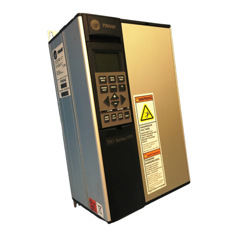
Trane LonWorks TR1 Series VFD User manual

Trane

Trane LonWorks TR1 Series VFD User manual

Trane LonWorks TR1 Series VFD User manual

Trane

Trane LonWorks TR1 Series VFD User manual

Trane 2TTB3 Series Assembly instructions

Trane

Trane 2TTB3 Series Assembly instructions

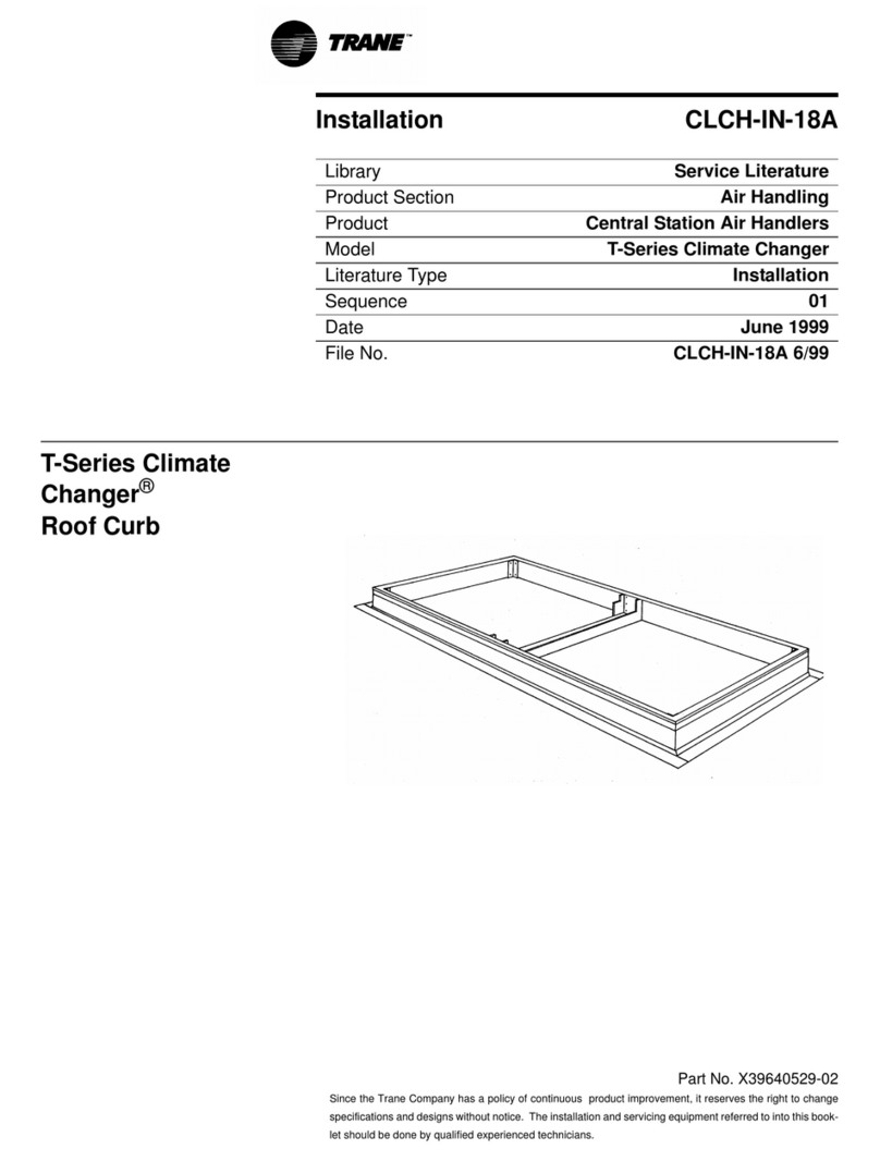
Trane CLCH-IN-18A User manual

Trane

Trane CLCH-IN-18A User manual

Trane WTS Installation and operating instructions

Trane

Trane WTS Installation and operating instructions

Trane WDS Installation and operating instructions

Trane

Trane WDS Installation and operating instructions

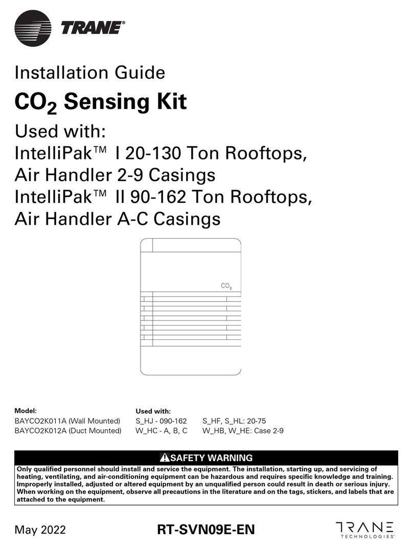
Trane BAYCO2K011A User manual

Trane

Trane BAYCO2K011A User manual

Trane Energy Wheels Owner's manual

Trane

Trane Energy Wheels Owner's manual

Trane 7722TX User manual

Trane

Trane 7722TX User manual

Trane CLCH-SVX02C-EN Owner's manual

Trane

Trane CLCH-SVX02C-EN Owner's manual

Trane BAYSENS050m User manual

Trane

Trane BAYSENS050m User manual

Trane ZUSTATALMS2 Assembly instructions

Trane

Trane ZUSTATALMS2 Assembly instructions

Trane Adaptive Frequency VFDB Installation and operating instructions

Trane

Trane Adaptive Frequency VFDB Installation and operating instructions

Trane UCM 4.0 and WirelessVAV Communication Specifications

Trane

Trane UCM 4.0 and WirelessVAV Communication Specifications

Trane Air-Fi WCS-SB Installation and operating instructions

Trane

Trane Air-Fi WCS-SB Installation and operating instructions

Trane WTS Installation and operating instructions

Trane

Trane WTS Installation and operating instructions

Trane WZS User manual

Trane

Trane WZS User manual

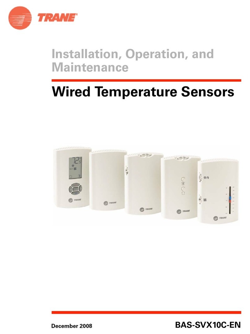
Trane Wired Temperature Sensors Installation and operating instructions

Trane

Trane Wired Temperature Sensors Installation and operating instructions

Popular Accessories manuals by other brands

Kodak PPS600 user manual

Kodak

Kodak PPS600 user manual

Temposonics V R Series Operation manual

Temposonics

Temposonics V R Series Operation manual

PCB Piezotronics 123 Series Operation manual

PCB Piezotronics

PCB Piezotronics 123 Series Operation manual

CHIEF PAC780 installation instructions

CHIEF

CHIEF PAC780 installation instructions

Inxpect MSK-101 Advanced configuration manual

Inxpect

Inxpect MSK-101 Advanced configuration manual

SUTO S418 Instruction and operation manual

SUTO

SUTO S418 Instruction and operation manual

Pepperl+Fuchs LVL-Z121 manual

Pepperl+Fuchs

Pepperl+Fuchs LVL-Z121 manual

Orion 90mm f/10.1 refractor Instruction manuals

Orion

Orion 90mm f/10.1 refractor Instruction manuals

Schwaiger ZHD01 user manual

Schwaiger

Schwaiger ZHD01 user manual

SIBOASI S4015 user manual

SIBOASI

SIBOASI S4015 user manual

PMT Tamson Cool Cube user manual

PMT

PMT Tamson Cool Cube user manual

Vivint V-FLD001-345 quick reference

Vivint

Vivint V-FLD001-345 quick reference

Hotron SSS-5 Quick installation guide

Hotron

Hotron SSS-5 Quick installation guide

Bartington Mag585 Operation manual

Bartington

Bartington Mag585 Operation manual

NUVOO NVO-EB01BK instruction manual

NUVOO

NUVOO NVO-EB01BK instruction manual

Rice Lake IQ plus 800 Installation & operation manual

Rice Lake

Rice Lake IQ plus 800 Installation & operation manual

Bibby Sterilin Stuart SI500 Instructions for use

Bibby Sterilin

Bibby Sterilin Stuart SI500 Instructions for use

Doro MemoryPlus 335 owner's guide

Doro

Doro MemoryPlus 335 owner's guide

manuals.online logo
manuals.online logoBrands
  • About & Mission
  • Contact us
  • Privacy Policy
  • Terms and Conditions

Copyright 2025 Manuals.Online. All Rights Reserved.