10 MSK-101| Advanced configuration manual v1.8 APR 2019 |msk-101_advanced-config_en_wo v1.8|© 2017-2019 Inxpect SpA
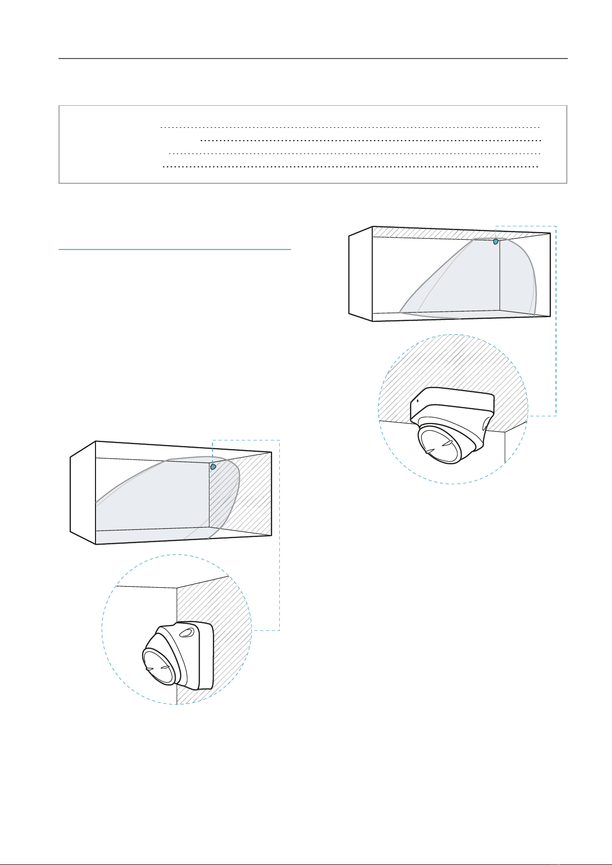
Side view.
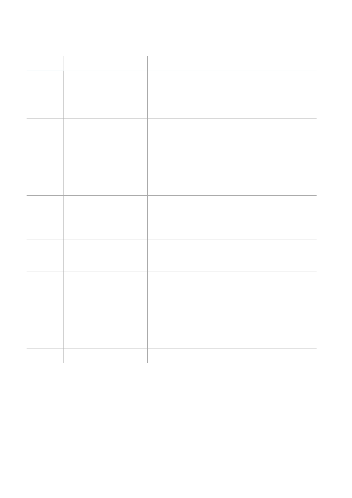
2.3.2 Range of the field with
vertical sensor direction (barrier)
In this installation the visual field of the sensor is
approximately 30° along the horizontal plane and
70° on the vertical plane. It extends for a
maximum of 20 m, following the radiation pattern
of the antenna.
Top view.
Side view.
2.3.3 Calculation of the field of
vision
The actual field of vision of the sensor (detection
start and end, s1and s3) depends on:
lsensor installation height (h)
lsensor direction (horizontal or vertical)
lsensor inclination (α)
Within the field of vision, discernment of animals
is guaranteed up to a certain distance from the
sensor (s2). For details about discerning animals,
see "Set the tolerance level for animals" on
page24.
Based on a specific installation height, there are
direction and inclination combinations that
guarantee optimum performance. Some
examples to better explain the effects of height
and inclination are presented as follows.
2.3.4 Sensor installation height
The sensor can be installed at any distance from
the plane to be monitored, from 0.5 and 3 m
(from 1.6 to 10 ft). For example, it can be installed
at 2 m from the floor or 0.5 m from the jamb of
the window frame.
When installing the sensor, consider the risk of a
blind spot: if the sensor is too high, it must be
tilted downwards to reduce the undetected area.
However, this also reduces the maximum
detected distance. If the sensor is too low, the
blind spot is minimal, but it increases the risk of
masking caused by accidental passage of people.
2.3.5 Examples of the field of
vision with horizontal sensor
direction (volumetric)
NOTICE: the detection start and end values do not
guarantee detection of a standing person. The
reported values may slightly vary based on the
installation conditions.
Note: only some heights are reported, but every
intermediate value is allowed and guarantees optimum
performance.
The dimensions of the field of vision expressed in
meters and feet are as follows.
h (m) α (°) s1(m) s2(m) s3(m)
1 0 0.5 * 20
1.5 0 0.5 20 20
2 -15 2.5 16 16
2 -30 2 7.5 10
2.5 -15 3 17 17
2.5 -30 2.5 7 10
2.5 -45 2 6.5 6.5
3 -30 2.5 7 10
3 -45 2 4.5 6.5
h (ft) α (°) s1(ft) s2(ft) s3(ft)
3.2 0 1.6 * 65
4.9 0 1.6 65 65
6.5 -15 8.2 52 52
6.5 -30 6.5 25 32
8.2 -15 9.8 55 55
8.2 -30 8.2 23 32
8.2 -45 6.5 21 21
10 -30 8.2 23 32
10 -45 6.5 15 21
Note *: discernment of animals is not guaranteed in the
entire field of vision.
2. Useful information for design