manuals.online logo
Brands
  1. Home
  2. •
  3. Brands
  4. •
  5. Trane
  6. •
  7. Controllers
  8. •
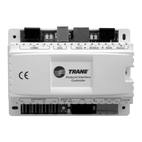
  9. Trane Tracer MP581 User manual

Trane Tracer MP581 User manual

Other manuals for Tracer MP581

2

This manual suits for next models

1

Other Trane Controllers manuals

Trane Tracer AH541 Assembly instructions

Trane

Trane Tracer AH541 Assembly instructions

Trane Tracer ZN521 Owner's manual

Trane

Trane Tracer ZN521 Owner's manual

Trane TR1 6002 User manual

Trane

Trane TR1 6002 User manual

Trane Oxbox JAYLOAM002 User manual

Trane

Trane Oxbox JAYLOAM002 User manual

Trane TR150 Operating instructions

Trane

Trane TR150 Operating instructions

Trane Mini User manual

Trane

Trane Mini User manual

Trane ReliaTel User manual

Trane

Trane ReliaTel User manual

Trane Tracer ZN511 Owner's manual

Trane

Trane Tracer ZN511 Owner's manual

Trane Symbio 210 Installation and operating instructions

Trane

Trane Symbio 210 Installation and operating instructions

Trane Tracer MP581 Manual

Trane

Trane Tracer MP581 Manual

Trane Symbio 800 User manual

Trane

Trane Symbio 800 User manual

Trane Symbio 210 Installation and operating instructions

Trane

Trane Symbio 210 Installation and operating instructions

Trane mP30 Owner's manual

Trane

Trane mP30 Owner's manual

Trane CONTH01AAUTOA Assembly instructions

Trane

Trane CONTH01AAUTOA Assembly instructions

Trane Tracer User manual

Trane

Trane Tracer User manual

Trane ZN. LonWorks control User manual

Trane

Trane ZN. LonWorks control User manual

Trane Tracer CH535 User manual

Trane

Trane Tracer CH535 User manual

Trane TCONTCCMHCM04A User manual

Trane

Trane TCONTCCMHCM04A User manual

Trane TCONT 800 Series Installation and operating instructions

Trane

Trane TCONT 800 Series Installation and operating instructions

Trane VAV VV550 LonTalk User manual

Trane

Trane VAV VV550 LonTalk User manual

Trane Tracer SC User manual

Trane

Trane Tracer SC User manual

Trane SmartGen HSC940 User manual

Trane

Trane SmartGen HSC940 User manual

Trane Tracer CH535 User manual

Trane

Trane Tracer CH535 User manual

Trane Tracer UC600 Quick setup guide

Trane

Trane Tracer UC600 Quick setup guide

Popular Controllers manuals by other brands

Sunricher SR-ZV9003T3-RGBW-US Installation

Sunricher

Sunricher SR-ZV9003T3-RGBW-US Installation

Ksenia intro Installation and configuration manual

Ksenia

Ksenia intro Installation and configuration manual

Inovance CAN200 Series manual

Inovance

Inovance CAN200 Series manual

Gauzy LC6 FLEX Controller Installation and operation guide

Gauzy

Gauzy LC6 FLEX Controller Installation and operation guide

Viking SLP-1 Technical practice

Viking

Viking SLP-1 Technical practice

CKD KBX-30E-U Series instruction manual

CKD

CKD KBX-30E-U Series instruction manual

Sharp Energy Sun Flux User manual & installation guide

Sharp Energy

Sharp Energy Sun Flux User manual & installation guide

Yamaha RCX40 user manual

Yamaha

Yamaha RCX40 user manual

AB Quality PowerFlex 400 Frames D-H Service bulletin

AB Quality

AB Quality PowerFlex 400 Frames D-H Service bulletin

Yamaha MJC8 owner's manual

Yamaha

Yamaha MJC8 owner's manual

AL-KO ATC operating instructions

AL-KO

AL-KO ATC operating instructions

Savant SmartControl 2 Deployment guide

Savant

Savant SmartControl 2 Deployment guide

GameSir T3S user manual

GameSir

GameSir T3S user manual

Kostal inveor operating manual

Kostal

Kostal inveor operating manual

Emerson Yarway 20-55 Operating and safety instructions

Emerson

Emerson Yarway 20-55 Operating and safety instructions

CoCo ACM-LV24 Quick installation guide

CoCo

CoCo ACM-LV24 Quick installation guide

Brooks SLA5810/20 Installation and operation manual

Brooks

Brooks SLA5810/20 Installation and operation manual

SIGMA TEK SR 011 Technical manual

SIGMA TEK

SIGMA TEK SR 011 Technical manual

manuals.online logo
manuals.online logoBrands
  • About & Mission
  • Contact us
  • Privacy Policy
  • Terms and Conditions

Copyright 2025 Manuals.Online. All Rights Reserved.

3
1
2
SAFETY WARNING
Only qualified personnel should install and service the equipment. The installation,
starting up, and servicing of heating, ventilating, and air-conditioning equipment
can be hazardous and requires specific knowledge and training. Improperly
installed, adjusted or altered equipment by an unqualified person could result in
death or serious injury. When working on the equipment, observe all precautions in
the literature and on the tags, stickers, and labels that are attached to the
equipment.
© 2020 Trane
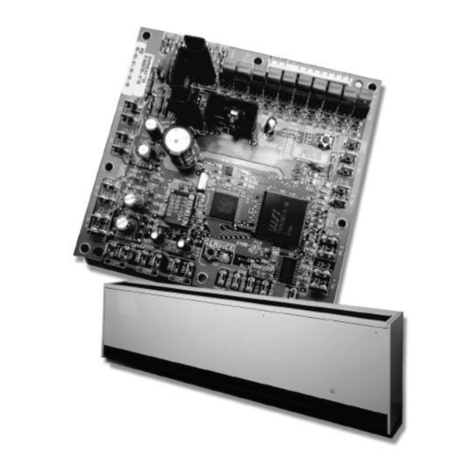
The frame-mounted Tracer MP581 controller can be used to replace
controllers in existing equipment or can be mounted in new equipment or
custom enclosures.
Note: The board shipped with these instructions (marked P/N 6400-2580-
01 or higher) requires firmware Version 4.00.007 or newer to function
correctly. Do not downgrade firmware below Version 4.00.007.
Warnings, Cautions, and Notices
Read this manual thoroughly before operating or servicing this unit.
Safety advisories appear throughout this manual as required. Your
personal safety and the proper operation of this machine depend upon
the strict observance of these precautions.
Important Environmental Concerns
Scientific research has shown that certain man-made chemicals can
affect the earth’s naturally occurring stratospheric ozone layer when
released to the atmosphere. In particular, several of the identified
chemicals that may affect the ozone layer are refrigerants that contain
Chlorine, Fluorine and Carbon (CFCs) and those containing Hydrogen,
Chlorine, Fluorine and Carbon (HCFCs). Not all refrigerants containing
these compounds have the same potential impact to the environment.
Trane advocates the responsible handling of all refrigerants-including
industry replacements for CFCs such as HCFCs and HFCs.
Important Responsible Refrigerant Practices
Trane believes that responsible refrigerant practices are important to the
environment, our customers, and the air conditioning industry. All
technicians who handle refrigerants must be certified according to local
rules. For the USA, the Federal Clean Air Act (Section 608) sets forth the
requirements for handling, reclaiming, recovering and recycling of
certain refrigerants and the equipment that is used in these service
procedures. In addition, some states or municipalities may have
additional requirements that must also be adhered to for responsible
management of refrigerants. Know the applicable laws and follow them.
The three types of advisories are defined as follows:
WARNING Indicates a potentially hazardous situation
which, if not avoided, could result in death or
serious injury.
CAUTION Indicates a potentially hazardous situation
which, if not avoided, could result in minor or
moderate injury. It could also be used to alert
NOTICE Indicates a situation that could result in
equipment or property-damage only accidents.
Operating Environment
WARNING
Proper Field Wiring and Grounding Required!
Failure to follow code could result in death or serious injury. All field wiring
MUST be performed by qualified personnel. Improperly installed and grounded
field wiring poses FIRE and ELECTROCUTION hazards. To avoid these hazards,
you MUST follow requirements for field wiring installation and grounding as
described in NEC and your local/state electrical codes.
WARNING
Personal Protective Equipment Required!
Installing/servicing this unit could result in exposure to electrical, mechanical
and chemical hazards. Before installing/servicing this unit, technicians MUST
put on all Personal Protective Equipment (PPE) recommended for the work
being undertaken. ALWAYS refer to appropriate SDS sheets and OSHA
guidelines for proper PPE. When working with or around hazardous chemicals,
ALWAYS refer to the appropriate SDS sheets and OSHA guidelines for
information on allowable personal exposure levels, proper respiratory
protection and handling recommendations. If there is a risk of arc or flash,
technicians MUST put on all necessary Personal Protective Equipment (PPE) in
accordance with NFPA70E for arc/flash protection PRIOR to servicing the unit.
Failure to follow recommendations could result in death or serious injury.
Temperature: From -40°F to 158°F (-40°C to 70°C)
Humidity: 10%–90% non-condensing
Power Requirements: 21–27 Vac (24 Vac nominal), 50–60 Hz 76 VA
Altitude: 6,500 ft (2,000 m)
Installation: Category 3
Pollution: Category 2
Enclosure Requirements
Before installing the frame-mounted controller, ensure that the
enclosure or mounting space meets the following minimum
requirements:
• Clearance dimensions as shown below.
• 24 Vac dedicated power supply.
• Compliance with National Electrical Code™ (NEC) and applicable
local electrical codes for high-voltage power wiring to the enclosure.
.5 in. (13 mm)
3 in. (76 mm)
For Comm Wires
.5 in. (13 mm)
Part Number Location
6 in. (152 mm)
For I/O Wires
.5 in. (13 mm)
June 2020 BAS-SVN075P-EN
Installation Instructions
Frame-mounted Tracer® MP581
Controller
Order Number: BMTM000CAD00
3270 3335

4
7
5
6
©2020 Trane
Trane has a policy of continuous product and product data improvement and reserves
the right to change design and specifications without notice. We are committed to using
environmentally conscious print practices.
Trane - by Trane Technologies (NYSE: TT), a global climate innovator - creates
comfortable, energy efficient indoor environments for commercial and residential
applications. For more information, please visit trane.com or tranetechnologies.com.
Installing the Termination Board
1. Remove the controller from its packaging and separate the top and
bottom frames.
2. Using the bottom frame (with termination board) as a template, mark
the four (4) mounting hole locations on the mounting surface. If the
mounting surface is metal and earth grounded, mark the location of
the termination board ground hole. If not, proceed to the next step.
3. Set the controller aside and drill four (4) holes at the marked
mounting locations large enough for #8 (4 mm) screws [not supplied].
4. Secure the controller to the mounting surface with #8 (4 mm)
screws.
5. Provide an earth-to-ground connection using either of the following
options:
a. Drill a pilot hole at the termination board ground hole and install
a #8 (4 mm) screw through the ground hole. With this option, the
surface on which the bottom frame is mounted must be earth-
grounded; OR
b. Wire a ground connection from the 24 Vac common bus
termination to earth ground. Common bus terminations are
found on the board at 24VAC INPUT POWER.
NOTICE
Avoid Equipment Damage!
Self-tapping sheet metal screws can result in loose metal shards
which may damage the board or cause it to malfunction. Start and
then remove each screw to ensure metal shards are not present
before mounting the bottom frame and termination board.
8 in.
(
203 mm
)
.
375 in.
(
10 mm
)
9
.50 in.
(
241 mm
)
5.75 in.
(
146 mm
)
1
0.25 in.
(
260 mm
)
1 in
.
(
25 mm
)
1
.25 in.
(
31 mm
)
Installing the Main Circuit Board
The controller does not ship with the top plastic frame installed. The
board can be kept in its installed room location and programmed while
the enclosure is mounted and wired.
Note: It is not possible to program the main circuit board without
connecting it to a termination board. If choosing to program the main
circuit board in a different location, a termination board is required.
After completing programming, connect the circuit board to the
termination board. To begin, verify that the 24 Vac power cable is not
connected to the termination board, and then install the main circuit
board as shown below.
1. Hold the top frame (A) at a 90° angle to the bottom of frame (B).
2. Connect the 60-pin cable (C) to the 60-pin cable ejector slot (D) by
pressing down firmly on the cable until the ejector tabs collapse and
snap over the ends of the cable (refer to the bottom left inset above).
Then, connect the 20-pin cable (E) to the 20-pin slot (F).
3. Align the snaps on the top frame (G) with the mounting locks on the
bottom frame and then push the two frames together in the direction
B
A
C
D
E
F
Ground Screw
Important: The 60-pin cable ejector is designed to eject the 60-pin cable when disconnecting
(refer to the lower right inset above). Ensure that the slot keys are aligned when connecting
the 60-pin cable to the 60-pin cable
indicated by the arrows. For controllers with an operator display,
connect the operator-display cable to the circuit board.
4. Locate the 24 Vac power connector on the termination board and
then remove the mating plug and screw terminals. Attach the 24 Vac
power-supply cable to the screw terminals on the mating plug.
5. Connect the 24 Vac power cable to the termination board (H). The
green status LED will light.
Agency Listings and Compliance
The European Union (EU) Declaration of Conformity is available from
your local Trane® office.
G
H
BAS-SVN075P-EN 05 Jun 2020
Supersedes 3270 3335 N (Mar 2016)