User access
Clock
& Date
Year, Month, Day, Weekday
Schedule
Enable / Disable (Manual control)
7 days (Mo, Tu, We, Th, Fr, Sa, Su)
Day schedule
Four time periods (Morning, Day, Evening, Night)
Start time: Put a time
System mode: Auto, Heat, Cool or OFF
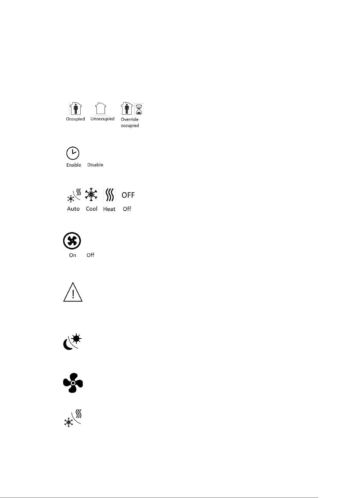
Occupancy mode: Occupied or Unoccupied
Setpoints
Linked to the Schedule
(Schedule enable)
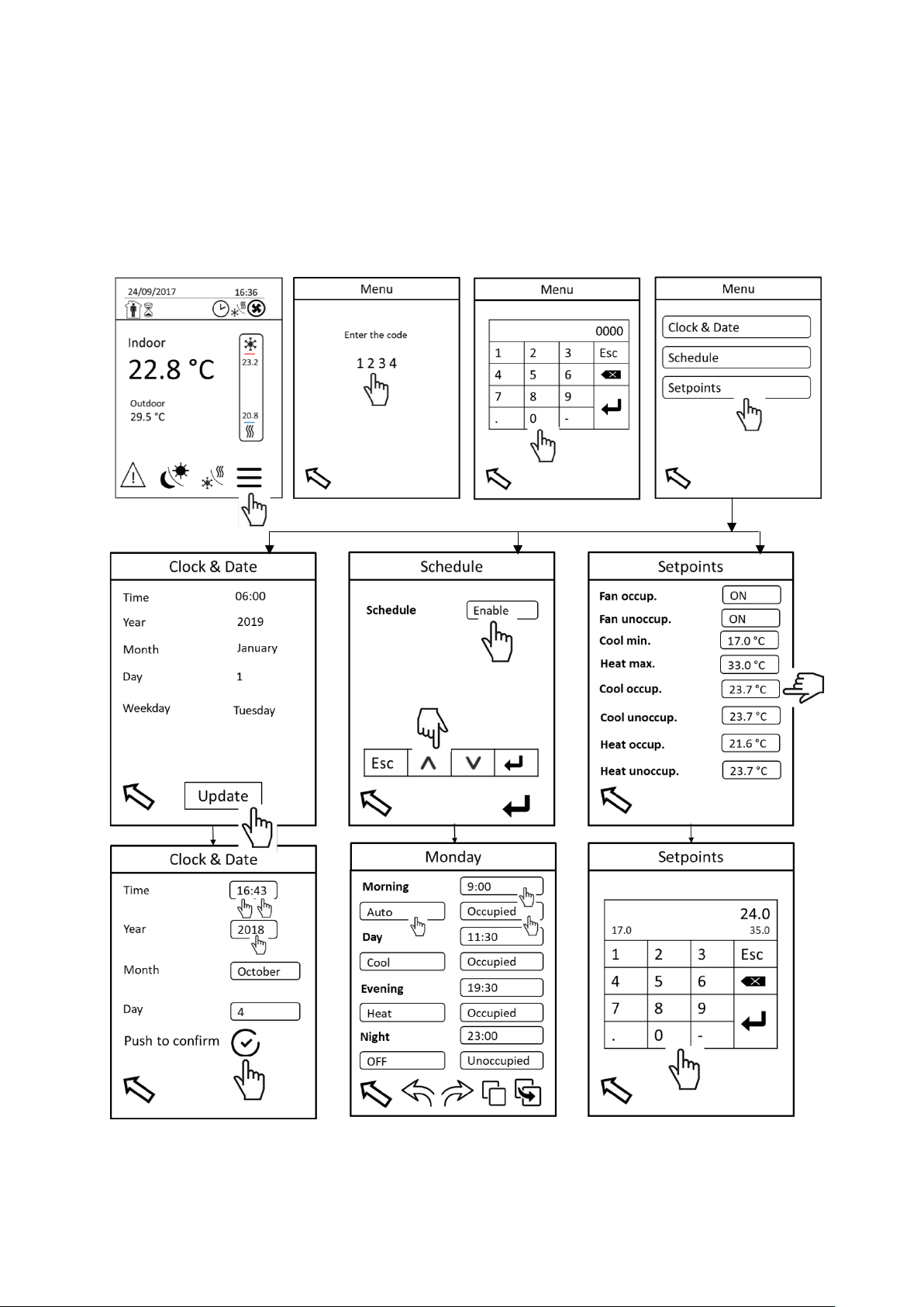
Menu access
Touch the 4 digits (1234) to display a keyboard and to type a code. Confirm by Enter key button of the keyboard to
access the menu.
Clock & Date
Touch Update button to set Clock & Date.
•Time: To set time it is needed to touch values of hours HH, confirm and then to touch and set minutes MM.
It has to be done separately although there is one borderline.
•Year: To set year in format YYYY.
•Month: To set actual month.
•Day: To set actual day in month.
•Push button to confirm, then Weekday is set automatically. Need to wait 1 s (refresh time) to display
correctly the right weekday before to return on previous screen.
Schedule
There are two possibilities to control the unit. With Schedule (Enable) or without schedule (Disable), which means
manual control.
In case of Schedule is Enable, the unit operates in defined time schedule, system and occupancy mode. Set Enable,
confirm on the keyboard and advance to Schedule sub-menu touching “Enter” button on the right bottom corner.
It is obliged to use and fill the four time periods of a day.
•Start time: Touch section of start time and set directly complete time on the displayed keyboard in format
HH:MM.
•System mode: Touch section of system mode and set required system mode.
•Occupancy mode: Touch section of occupancy mode and select occupied or unoccupied mode.
Occupied mode considers fresh air damper opening according to the required setting. No fresh air, fresh
air damper is closed when unoccupied mode is selected. Fresh air opening setting has to be carried out
in Service display.
•Touch copy button, use an arrow to go on another day and paste this schedule settings using paste button
if you need repeat the same schedule.
•To browse through the day schedules use right and left arrows.