Transmitter Solutions DOLCSAW10KH User manual

Model DOLCSAW10KH
A Waterproof Stand Alone
Proximity Reader
DOLCSAW10KH
User Manual

Function description
Change the mastercode
Add card user
Delete card user
To Unlock the door
To Unlock the door
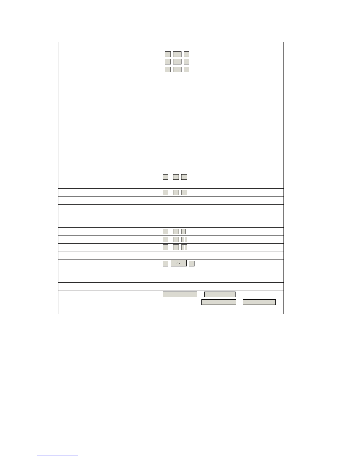
DOLCSAW10KH Quick Reference Programming Guide
Choose from the relevant function below and input
(Code must be 6-8 numbers)
(Can add cards continuously)
(Can delete cards continuously)
Read user card
Then you can do the programming
(888888 is the defualt factory mastercode)
Note: In order to start programming the master user must enter the
programming mode
Enter programming mode
To exit the programming mode
888888
New code Repeat new code
#
0
1 #Read card
#Read card2
# #
1. Packing List
Name Quantity Remark
DOLCSAW10KH 1
Infrared remote control 1
Manager add card 1
Manager delete card 1
Short Pin 1 Used for factory default setting
User manual 1
Self Tapping Screws 4/2 3.5*27mm
Please ensure that all the above contents are correct. If any are missing please notify the
supplier of the DOLCSAW10KH.
2

2. Description
The DOLCSAW10KH is fully waterproof stand alone Proximity access Reader, which uses an
advanced micro processor, equipped with large capacity Flash memory, it supports up to
10,000 cards. It can read both 125 KHz HID card and 125 KHz EM card. It is easy to add or
delete card users by using the master card; as well as, with the infrared remote control
programmer.
The DOLCSAW10KH not only has the features of low power consumption, automatic selection of
lock, anti vandal alarm and exit button, but also has protective function against input over
voltage and output short -circuit. The block enrollment function allows you to enroll a
maximum 10,000pcs HID cards or EM cards at a time within 10 minutes. These features
make the DOLCSAW10KH easy in operation, safe and reliable; it is an ideal choice for door
access.
3. Features
Standalone Card Reader
Waterproof, confirm to IP68
Use capacity: 10,000
Card interface: HID&EM 125KHZ card/tag
Remote control for programming
Manager cards for fast add and delete users
Card block enrollment
Can enroll a maximum of 10,000 cards at a time within 10 minutes
Wiegand26 input/output
Can be used as a slave reader
2 pcs DOLCSAW10KHW can be interconnected
Can be used as controller by connecting wiegand reader
Anti-Pass back Function
Alarm signal output, Door open detection
LED display; Full of 10000 users, recognizing speed <15ms.
3

4. Specifications
Supply Voltage DC12V±10%
User capacity 10,000
Sleeping Current <15mA
Card type HID&EM 125khz Card/Tag
Card Reading Distance 1.6 3.1 in
Wiegand interface Wiegand 26
Operating Temperature -13 140°F
Operating Humidity 20% 98%
Environment Confirm to IP68
Lock output load Max20A
Alarm output load Max20A
Adjustable Door Relay Time 00-99 seconds
Adjustable Alarm Time 0- 3 minutes
Wiring Connections Electric Lock, Exit Button, DOTL, External Alarm
Manager card Two
Dimensions 4-1/8 x 2 x 1 in
5. Installation
Drill holes on the wall or prepare the cassette.
Wire through the hole, and blanket the unused cable in case of short circuit.
Fix the back cover firmly on the cassette or t
AC
D
B
he wall.
Attach the reader to the back cover.
4
95.5 mm
61 mm
40 mm
Shielded
Cables
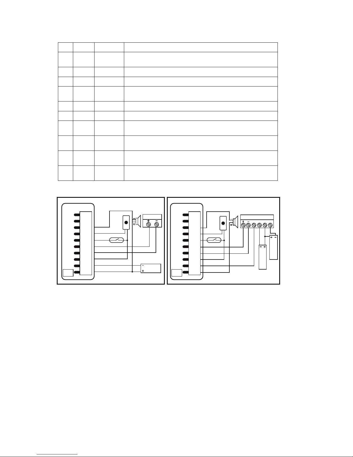
6. Wiring
No Color Function Description
1
Green
D0 Wiegand output, input signal wire D0
2 White
D1 Wiegand output, input signal wire D1
3 Grey ALARM+ connecting to the negative pole of the alarm equipment
4
Yellow
OPEN To connect to one part of Exit Button
5 Brown
D_IN Door Contact input,
6 Red
12V (+) 12Vdc Positive Regulated Power Input
7 Black
GND (-) Negative Regulated Power Input
8 Blue
VSS the negative pole of the controller, connect to the other part of Exit
button and door contact
9
Purple
L- Connect to the negative pole of the Lock
10
Orange
L+/Alarm+ Connect to the positive pole of the lock and alarm equipment
Connection Diagram
Note: Do not power on until all wiring has been completed
7.
To Reset to Factory Default
Power off, use the supplied Contact Pin to short out the 2P socket on the main board, then
power on, if successful, the beeper will beep twice, the LED shines in orange, remove the
Green
DOLCSAW10KH
J1
Special Power SupplyCommon Power Supply
DC12V/3A
Alarm
Lock
White
Grey
Yellow
Brown
Red
Black
Blue
Purple
Orange
D0
door detecting switch
door detecting switch
Fail-safe lock
Fail-secure lock
exit btn
D1
ALARM-
OPEN
D_IN
+12V
GND
VSS
L-
L+
ALARM+
Green
J1
Alarm DC12V/3A
White
Grey
Yellow
Brown
Red
Black
Blue
Purple
Orange
D0 exit btn
PUSH NC COM NO
D1
ALARM-
OPEN
D_IN
+12V
GND
VSS
L-
L+
ALARM+
5

Short Pin, then read the Two Manager cards (Manager add card firstly, Manager delete card
secondly), after that the LED turns red, which means the DOLCSAW10KH has been reset to factory
default setting. Remarks: Reset to factory default setting, the users' information enrolled is still
retained. When re-set to Factory setting, the two Manager cards must be re-enrolled.
9. DOLCSAW10KH Detailed Programming Guide
9.1 User settings
There are 2 ways to add and delete users:
A By manager card; - By remote control
A - By Manager card (The most convenient way)
To Add user by Manager Add Card Manager add card Read card Manager add
card Cards can be added continuously.
To Delete User by Manager Delete Card Manager delete card Read Card Manager
delete card Cards can be deleted continuously.
B- By Remote control
Enter into the programming mode firstly
To Enter the programming mode *
Manager Password #
888888 is the default factory master code
Remarks: All the steps below must be done after enter into programming mode
To change the master code 0
New Password # Repeat New Password #
The master code must be 6 8 digit number.
8. Sound and Light indication
Operation status LED Buzzer
Reset to factory default setting Orange blinks Two short ring
Sleeping mode Red flashes slowly
Operation successful Short ring
Enter into programming mode Red flashes Short ring
Enter into setting Orange flashes Short ring
Exit programming mode Red flashes slow Short ring
Operation failed Three short ring
Open the door Green flashes Short ring
Alarm Red flashes fast Alarm
6

7
9. DOLCSAW10KH Detailed Programming Guide (continued)
To add a card user (Method 1)
This is the faster way to enter cards using ID
number auto generation. The card can be
either be presented or input the 8 digit card
number from the card can be manually
entered
or
1
Read Card #
1 Input Card number (8 digit) #
Card can be added continuously without exiting
programming mode.
The card number is the last 8 digits of the number
printed on the card.
To add a card user (Method 2)
This is the alternative way to enter cards
using User ID Allocation. In this method a
User ID is allocated to a card. Only one user
ID can be allocated to a single card.
1 ID number # Read Card #
or
1 ID number # the Card number (8 digits) #
To add a series of card users – Block
Enrollment
(It can enroll maximum 10,000pcs cards at a
time within 10 minutes.)
8 8 digits Card number # Card
quantity #
Card quantity is between 1-10,000. Of the 8 digits
card number, for HID card, they are the 3 digits of
a facility code and 5 digits of a serial number; for
EM card, they are the last 8 digits on the card.
To delete a card user.
Note users can be deleted continuously
without exiting programming mode
2 Read Card # or
2 Card number #
To delete ALL users.
(Note: This option will delete all users but
Manager Cards. Be careful with use)
2 0000 #
9.2 Door setting
Lock power setting
Fail secure (Unlocked when power on)
This is the factory default, 3 seconds 4 0 99 #
0-99 is to set the door relay time 0 99 seconds.
Fail safe (unlocked when power is off)
5 0 99 #
0 99 is to set the door relay time 0 99 seconds.
Enter programming mode
Enter programming mode
Enter programming mode
Enter programming mode
Enter programming mode
Enter programming mode
Enter programming mode
9.2 Door setting (continued)
Anti-Pass Back Settings
Anti-Pass back Disabled (Factory default)
Anti-Pass back Master Mode:
Anti-Pass back Auxiliary Machinery Mode
(Note: the detailed wiring diagram and
illustration, please refer to the “Advanced
application”
3 0 #
3 1 #
3 2 #
Door open detection
Door Open Too Long (DOTL) warning. When used with an optional magnetic
contact or built-in magnetic contact of the lock, if the door is opened normally, but
not closed after 1 minute, the inside buzzer will beep automatically to remind
people to close the door and continue for 1 minute before switching off
automatically.
Door Forced Open warning. When used with an optional magnetic contact or built in
magnetic contact of the lock, if the door is forced open, or if the door is opened
after 120 seconds of the electro-mechanical lock not closed properly, the inside
buzzer and alarm output will both operate.
To disable door open detection.
(Factory default)
6 0 #
To enable door open detection 6 1 #
Security Mode Setting
Reader Lockout & Alarm Output options. If there are 10 invalid cards or 10 incorrect
PIN numbers in a 10 minute period either the reader will lockout for 10 minutes or the
alarm will operate for 10 minutes, depending on the option selected below.
Normal status (No lockout or Alarm) 7 0 # (Factory default setting)
Keypad Lockout 7 1 #
Alarm Output 7 2 #
Alarm output time
To set the alarm output time (0-3
minutes) Factory default is 1 minute
9
0 3 #
To remove the alarm
To remove the Door Forced Open warning Read valid card or Master Code#
To remove the Door Open Too Long
warning
Close the door or Read valid card or Master Code #
8

To Unlock the door
To Unlock the door
Read
User
card
(Note that Manager Card can t be used as User Card
to unlock the door.)
10. Advanced Application
10.1 DOLCSAW10KH operating as a Controller
In this mode the DOLCSAW10KH supports a Wiegand 26 bit input so an external Wiegand device
with a 26 bit output can be connected to the Wiegand input terminals on the DOLCSAW10KH.
Either an ID card reader (125 KHZ) or an IC card reader (13.56 MHZ) can be connected to the
DOLCSAW10KH Cards are required to be added at the external reader, except where an external
ID reader is used, in this case cards can be added at either reader or controller. See figure 1
Figure 1
10.2 DOLCSAW10KH operating as a Wiegand Output Reader
In this mode the DOLCSAW10KH supports a Wiegand 26 bit output so the Wiegand data
lines can be connected to any controller which supports a Wiegand 26 bit input. See figure 2
Green
GND Em card
Ic card
HID card
+12V
D1
D0
reader plug
DOLCSAW10KH Controller
J1
Power
DC12V/3A
Alarm
Wiegand reader
Lock
White
Grey
Yellow
Brown
Red
Black
Blue
Purple
Orange
D0
door detecting switch exit btn
D1
ALARM-
OPEN
D_IN
+12V
GND
VSS
L-
L+
ALARM+
9

10
Figure 2
10.3 Two DOLCSAW10KH units interconnected for a single door
In this mode two DOLCSAW10KH units are used for a single door, one for entry and the other for
exit. Either device acts as the controller and reader at the same time. Users can be enrolled
on either of the devices. In this mode the user capacity for one door can be up to 20,000. The
setting of the two DOLCSAW10KH units must be the same including the master code. See figure 3
Figure 3
Green
White
Grey
Yellow
Brown
Red
Black
Blue
Purple
Orange
Green
Indoor
J1 J1
DOLCSAW10KH controller 1 DOLCSAW10KH controller 2
Outdoor
Power
DC12V/3A
Alarm
Lock
White
Grey
Yellow
Brown
Red
Black
Blue
Purple
Orange
D0
door detecting switch exit btn
D1
ALARM-
OPEN
D_IN
+12V
GND
VSS
L-
L+
ALARM+
D0
D1
ALARM-
OPEN
D_IN
+12V
GND
VSS
L-
L+
ALARM+
Green
White
Grey
Yellow
Brown
Red
Black
Blue
Purple
Orange
DOLCSAW10KH
D0
D1
+12V
GND
Power supply
D0
D1
ALARM-
OPEN
D_IN
+12V
GND
VSS
L-
L+
ALARM+
J1
Controller
Controller with wiegand 26 input

reader the user can‘t exit from the controller inside, also, the user can‘t enter in and
exit continuously.
10.5 Anti-Pass Back for 2 doors
See Figure
4 for the Connection Diagram. Door 1 with one DOLCSAW10KH and Door 2 with
one DOLCSAW10KH, set DOLCSAW10KH on Door 1 as the Anti-Pass Back Auxiliary unit (3 2 #),
and set the
other DOLCSAW10KH on Door 2 as the Anti-Pass Back Master unit (3 1 #). Then
they build up a
two doors anti-pass back system,
which is normally used for a parking lot…etc
The operation and function is shown below:
5.1 Set the needed function and enroll the User Cards from DOLCSAW10KH Anti-Pass Back
Master unit on Door 2.
5.2 With the valid user card, the user can only enter in from Door 1, and exit from Door 2. On
the other hand, without entering record from the Auxiliary unit, the user can t exit from the
Master unit or Auxiliary unit, also, the user can t enter in and exit continuously.
10.4 Anti-Pass back for single door (3 1 #)
See Figure 1 for the connection diagram. Install one Wiegand reader (or a DOLCSAW10KH
without user information as reader) outside the door, connecting to one DOLCSAW10KHController
inside the door which acts as the Anti-Pass Back Master unit. Of the two devices, they build
up an anti-pass backsystem for single door. The operation and function is as below:
4.1 Set the needed function and enroll the User Cards on the inside DOLCSAW10KH Anti-
Pass Back Master unit.
4.2 With the valid user card, the user can only enter the door from the outside reader, and exit
from the inside DOLCSAW10KH
Controller. On the other hand, without entering record from the
11

Table of contents
Other Transmitter Solutions Door Lock manuals


