Transmitter Solutions ICE-LOCK User manual

ICE$LOCK(
GSM$Code$Lock$access$control$unit$
$
(
(
INSTALLATION(MANUAL(

ICE6LOCK$
INSTALLATION$MANUAL(
Page%2%
$
Contents
1!FOR YOUR SAFETY.......................................................................................... 5!
2!INTRODUCTION............................................................................................... 6!
3!FEATURES AND APPLICATIONS ........................................................................ 7!
4!START UP...................................................................................................... 8!
5!LED DISPLAY ................................................................................................. 9!
6!CLEAR ALL PROGRAMMED DATA FROM SIM ......................................................10!
7!CONNECTION DIAGRAM ..................................................................................11!
8!PROGRAMMING ICE-LOCK................................................................................12!
9!THE ICE-LOCK PARAMETERS ...........................................................................13!
9.1!ALARM SUPPORT .................................................................................................................................. 13!
9.2!OUTPUT MANAGEMENT ........................................................................................................................ 16!
9.3!DIRECT ACCESS BY ENTERING PIN ACCESS CODES VIA ILLUMINATED KEYPAD ................................... 17!
9.4!SECURITY LEVEL -SL ........................................................................................................................... 19!
9.5!PREPAID CARD CREDIT AND VALIDITY INFORMATION .......................................................................... 20!
9.6!SET-UP PARAMETERS ........................................................................................................................... 22!
9.7!SMS MESSAGES EDITOR........................................................................................................................ 25!
9.8!CLIP ...................................................................................................................................................... 26!
9.9!SPECIAL SMS COMMANDS .................................................................................................................... 28!
10!PRINT-OUT OF THE PARAMETERS ..................................................................30!
10.1!RECEIVE ALL PARAMETERS (PALL).................................................................................................... 30!
10.2!CHECK SW REVISION (PSW) ............................................................................................................... 30!
10.3!CHECK SIGNAL QUALITY (PSQ) .......................................................................................................... 30!
10.4!RECEIVE TELEPHONE NUMBERS (PTN) ............................................................................................... 30!
10.5!RECEIVE LINKS (PLN) ......................................................................................................................... 30!
10.6!RECEIVE INPUT PARAMETERS (PIN).................................................................................................... 31!
10.7!RECEIVE INPUT FILTER VALUE (PID)................................................................................................... 31!
10.8!RECEIVE OUTPUT FILTER VALUE (POD) ............................................................................................. 31!
10.9!RECEIVE DELAY BEFORE DIAL VALUE (PDD)...................................................................................... 31!
10.10!RECEIVE ACCESS TELEPHONE NUMBERS (PSL) .................................................................................. 31!
10.11!RECEIVE OUTPUT PARAMETERS (POS) ............................................................................................... 31!
10.12!RECEIVE ALL PROGRAMMED SMS MESSAGES (P#) ............................................................................. 32!
10.13!RECEIVE SET UP PARAMETERS VALUE (PPA) ..................................................................................... 32!
10.14!RECEIVE CREDIT PARS PARAMETERS (PCREF) .................................................................................... 32!
10.15!RECEIVE CREDIT CHECK TELEPHONE NUMBERS (PCN) ....................................................................... 32!
10.16!RECEIVE ALL CLIP PARAMETERS (PCLP) ............................................................................................ 32!

ICE6LOCK$
INSTALLATION$MANUAL(
Page%3%
10.17!RECEIVE STATE OF THE CREDIT FOR THE PREPAID CARD .................................................................. 33!
10.18!RECEIVE STATE OF THE OUTPUTS (PORC) ......................................................................................... 33!
10.19!MANUAL GSM MODULE RESTART (MRES)........................................................................................... 33!
10.20!RECEIVE STATUS OF INPUTS (INS) ..................................................................................................... 33!
10.21!RECEIVE PIN ACCESS CODES PARAMETERS (PPIN)............................................................................. 33!
10.22!RECEIVE ICE-LOCK LOG ...................................................................................................................... 34!
11!CHANGING PARAMETERS USING THE SMS COMMANDS......................................35!
12!DEFAULT SETTINGS ON ICE-LOCK .................................................................37!
13!PARAMETERS PRINT-OUT COMMANDS ............................................................39!
14!TECHNICAL SPECIFICATIONS.........................................................................40!
Figures
Figure 1: ICE-LOCK Connection diagram.................................................................11!
Figure 2: Input Connection diagram .......................................................................14!
Figure 3: Output Connection diagram ....................................................................16!
Tables
Table 1: IN, ID and DD parameters .........................................................................14!
Table 2: IN, ID, DD parameters example.................................................................14!
Table 3: Remote alarm reporting parameters.........................................................15!
Table 4: Remote alarm reporting example .............................................................16!
Table 5: Output management parameters .............................................................17!
Table 6: Output management parameters example ...............................................17!
Table 7: Entering PIN access code parameters ......................................................18!
Table 8: Entering PIN access codes example..........................................................18!
Table 9: SL parameter............................................................................................19!
Table 10: SL example .............................................................................................19!
Table 11: Prepaid card validity parameters............................................................21!
Table 12: Credit example .......................................................................................22!
Table 13: Set-up parameters .................................................................................24!
Table 14: Set-up parameters example ...................................................................24!
Table 15: Message parameters ..............................................................................25!

ICE6LOCK$
INSTALLATION$MANUAL(
Page%4%
Table 16: Message parameters example ................................................................25!
Table 17: CLIP parameters .....................................................................................27!
Table 18: CLIP parameters example .......................................................................27!
Table 19: LOG parameters .....................................................................................27!
Table 20: LOG parameters example .......................................................................28!
Table 21: SMS commands. .....................................................................................29!
Table 22: SMS commands example. .......................................................................29!
Table 23 ICE-LOCK default settings .......................................................................38!
Table 24: ICE-LOCK parameters print out commands............................................39!

ICE6LOCK$
INSTALLATION$MANUAL(
Page%5%
1 FOR YOUR SAFETY
Read these simple guidelines. Not following them may be dangerous or illegal. Read
the complete user guide for further information.
SWITCH ON SAFELY
Do not switch the unit on when use of wireless phone is prohibited or when it may
cause interference or danger.
INTERFERENCE
All wireless phones and units may be susceptible to interference, which could
affect performance.
SWITCH OFF IN HOSPITALS
Follow any restrictions. Switch the unit off near medical equipment.
SWITCH OFF IN AIRCRAFT
Follow any restrictions. Wireless devices can cause interference in aircraft.
SWITCH OFF WHEN REFUELING
Do not use the unit at a refueling point. Do not use near fuel or chemicals.
SWITCH OFF NEAR BLASTING
Follow any restrictions. Do not use the unit where blasting is in progress.
USE SENSIBLY
Use only in the normal position as explained in the product documentation. Do not
touch the antenna unnecessarily.

ICE6LOCK$
INSTALLATION$MANUAL(
Page%6%
2 INTRODUCTION
ICE-LOCK is a universal remote controller based on GSM technology. It is designed
as unlimited range, wire free, low cost, and highly robust remote control system.
As all other devices from portfolio, ICE-LOCK supports alarm detection, stay-alive
messages, credit checking etc…
The ICE-LOCK is a GSM remote control unit with CodeLock keypad which can open
automated electric gates. You can dial the number of the ICE-LOCK unit free of
charge (Caller ID) or type your unique entry code into CodeLock keypad. When the
call is received or the correct code is recognized, the ICE-LOCK unit opens the
gates.
Changing the phone numbers, setting the codes can be programmed by sending
simple SMS to the unit or via WEB (Option on special request).
Typical use of the ICE-LOCK: rental apartments, holiday houses, restricted access
areas, storages, laboratories, etc.
ICE-LOCK is equipped with relay output.

ICE6LOCK$
INSTALLATION$MANUAL(
Page%7%
3 FEATURES AND APPLICATIONS
Features:
⇒Built-in 2 or 4 band GSM module
⇒Up to 50 PIN access codes (4 digit)
⇒1 alarm input
⇒1 output (relay supported)
⇒Up to 50 telephone numbers for CLIP support
⇒Programming by USB on the ICE-LOCK
⇒Programming by SMS command – all parameters including the PIN access codes
⇒Anti-tampering input
Applications:
⇒Free of charge access control by typing 4 digit PIN access code on the keypad
⇒Free of charge remote control (CLIP)
⇒Simple alarm support

ICE6LOCK$
INSTALLATION$MANUAL(
Page%8%
4 START UP
⇒Insert SIM card to be used for ICE-LOCK in your personal mobile phone.
IMPORTANT
ERASE THE PIN CODE ON THE SIM CARD!
⇒Insert SIM card in ICE-LOCK device.
The unit must be switched OFF when you insert the SIM!
⇒Connect the external antenna to antenna connector.
⇒Connect input and output to ICE-LOCK.
⇒Connect power cable to ICE-LOCK device
⇒Connect device to source power supply voltage.
⇒Wait until LED1 (green) starts flashing. This is set in around 30 seconds.
⇒ICE-LOCK unit is now ready to operate.
IMPORTANT
Before sending any SMS commands to ICE-LOCK device,
device must be powered ON and in normal operation!

ICE6LOCK$
INSTALLATION$MANUAL(
Page%9%
5 LED DISPLAY
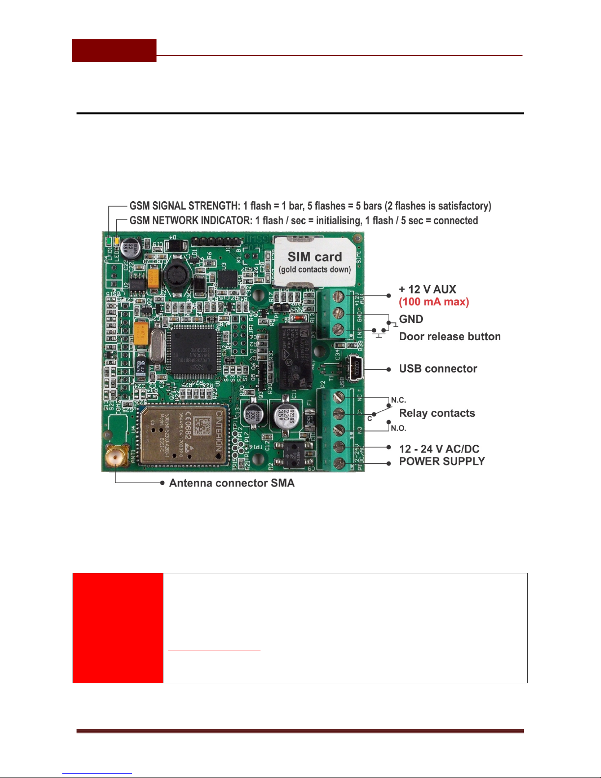
Green LED (LED1)
- Indicates the level of the GSM signal from 1 to 5 LED flashes (1 is weak
signal, 5 is excellent signal)
Yellow LED (LED2)
- Short flashing indicates that the GSM module is ON, but it is not yet
connected on the GSM network. After connection, yellow led is flashing with
short pulse (0,5s) ON and a long pulse OFF (5s).

ICE6LOCK$
INSTALLATION$MANUAL(
Page%10%
6 CLEAR ALL PROGRAMMED DATA FROM SIM
This is highly recommended when a SIM card you are going to use for the ICE-
LOCK is not new and it already has some data stored in the phone book memory.
By sending this SMS to ICE-LOCK all programmed parameters and numbers are
cleared:
;SDCLR;
After the command is received by the device all configuration parameters on the
SIM card including the SMS are deleted. The procedure can take up-to 2 minutes,
depends on the version of the SIM card.
The ICE-LOCK will restart after the configuration is deleted.
NOTE
By sending this command to the ICE-LOCK ALL DATA are erased from
the SIM card, including SMS!
ICE6LOCK$
INSTALLATION$MANUAL(
Page%11%
7 CONNECTION DIAGRAM
Before connecting the ICE-LOCK please take a look at connection diagram very
carefully.
Figure 1: ICE-LOCK Connection diagram
VERY
IMPORTANT
Do not use the +12V AUX power output for electric
lock driving!
You can use it to power external sensors only
(100mA max)!
Use separate power source for door electric lock!

ICE6LOCK$
INSTALLATION$MANUAL(
Page%12%
8 PROGRAMMING ICE-LOCK
ICE-LOCK device supports different types of programming:
⇒You can program ICE-LOCK remotely by SMS command. You can program all
parameters including the PIN access codes (PINx parameters).
⇒You can program ICE-LOCK directly with the use of USB connection on the
device. You can program all parameters except PIN access codes.
Programming of PIN access codes is not supported yet on EasySet SW, you
can program them by sending simple SMS message to the unit.
If there is no CD with the program and drivers in your package, please
contact your reseller to receive the application running on PC for
management of the ICE-LOCK and the appropriate USB drivers.

ICE6LOCK$
INSTALLATION$MANUAL(
Page%13%
9 THE ICE-LOCK PARAMETERS
To support versatile functionality of ICE-LOCK different parameters are used. The
parameters are divided in logical sections and are described in the following
chapters.
9.1 ALARM SUPPORT
Alarm reporting is supported by group of different parameters. First section is
used to define the relations needed for alarm to be trigged. The second section is
used to report alarm.
9.1.1 ALARM TRIGGERING
Parameters are used to control (filter) the triggering of the alarm inputs.
9.1.1.1 IN parameters
Alarm and reset input can be triggered in 4 different ways. The status of the input
can either be normal closed (N.C) or normal open (N.O.) with positive (+ 12V) or
negative (GND) voltage.
Activation of the input/alarm is reported by IN1 values 0 to 2. It the user needs to
receive information of the input/alarm restores use IN1 values 4 to 6. IN1 value 3
disables the input/alarm reporting.
⇒IN = 0 – Normal Open – triggered with negative voltage (GND)
⇒IN = 1 – Normal Close – breaking negative or positive voltage loop
⇒IN = 2 – Normal Open – triggered with positive voltage (+ 12VCC)
⇒IN = 3 – Not in use
⇒IN = 4 => IN = 0 + input reset SMS
⇒IN = 5 => IN = 1 + input reset SMS
⇒IN = 6 => IN = 2 + input reset SMS

ICE6LOCK$
INSTALLATION$MANUAL(
Page%14%
Figure 2: Input Connection diagram
9.1.1.2 ID parameters
ID parameter determines time period of the pulse length to trigger the alarm. The
pulse time can be from 0,5 seconds to 9999 seconds. The default time is 0,5
seconds when the parameter value is 0.
Parameter is in seconds.
9.1.1.3 DD parameters
This parameter is used to define the delay between the time that alarm input is
trigged and the time that alarm is reported.
Parameter is in seconds.
9.1.1.4 Table of parameters
Name
Comment
IN1
Mode of operation for input 1
ID1
Input time integration delay on input 1
DD1
Time delay for alarm reporting on input 1
Table 1: IN, ID and DD parameters
Example:
♦Direct programming on the SIM card
ICE-LOCK PROGRAMMING TABLE
SIM CARD PHONE BOOK
Name
Number
Description
IN1
0
Alarm activated by connecting to GND
ID1
10
Input 1 has to be valid for 10second to trigger
the alarm
DD1
15
Reporting of the alarm on input 1 is delayed by
15s
Table 2: IN, ID, DD parameters example
♦Remote programming by SMS
;IN1=0;ID1=10;DD1=15;
ICE6LOCK$
INSTALLATION$MANUAL(
Page%15%
9.1.2 REMOTE REPORTING ALARM EVENTS
Parameters used to define the way to report the alarm event.
NOTE
ICE-LOCK device send SMS messages for reporting alarm events.
9.1.2.1 TN parameters
Telephone numbers for remote alarm reporting are listed as TN parameters.
Remote alarm reporting on ICE-LOCK is done via SMS messages.
9.1.2.2 LN parameters
This parameter is used to link alarm event from inputs or any other source to the
telephone numbers on TN list.
9.1.2.3 Table of parameters
Name
Comment
TN1
1st telephone number
TN2
2nd telephone number
TN3
3rd telephone number
TN4
4th telephone number
TN5
5th telephone number
LN1
Input & telephone No. linking for 1st alarm input (TN1 –
TN5)
LN3
Periodic test SMS. No. linking (TN1 –TN5)
LN4
SIM card refill. No. linking (TN1 –TN5)
LN5
NAC list. No. linking (TN1 –TN5)(see note)
LN6
Log status. No. linking (TN1 –TN5)
Table 3: Remote alarm reporting parameters
Example:
♦Direct programming on the SIM card
ICE-LOCK PROGRAMMING TABLE
SIM CARD PHONE BOOK
Name
Number
Description
TN1
042376678
1st telephone number
LN1
13
Input 1 reports alarm to TN1 & TN3
LN5
1
NAC event sent to TN1
ICE6LOCK$
INSTALLATION$MANUAL(
Page%16%
Table 4: Remote alarm reporting example
♦Remote programming by SMS
;TN1=042376678;LN1=13;LN5=1;
NOTE
When telephone number (calling or messaging ICE-LOCK) is not
authorized, not acknowledge event occurs (NAC). The telephone
number responsible for this event can be send to TN user for
notification.
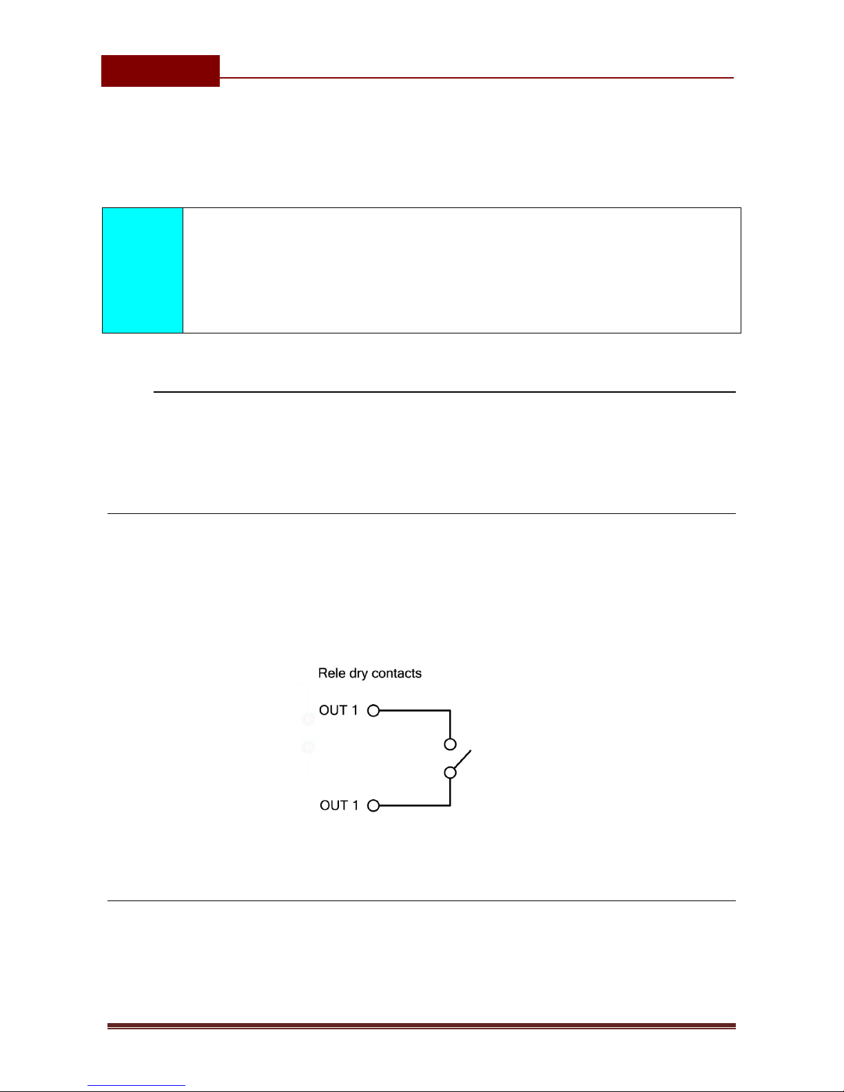
9.2 OUTPUT MANAGEMENT
ICE-LOCK supports the possibility to report alarms from inputs and any other
events locally via 1 output. The behavior is defined using next parameters
9.2.1 OS parameter
ICE-LOCK device has 1 dedicated relay supported outputs. Outputs can be
configured to different behavior:
⇒OSx = 0 – Disabled
⇒OSx = 1 – Bi-stable toggle mode
⇒OSx = yyy – Mono-stable pulse mode (duration in seconds)
Typical connection for the output:
Figure 3: Output Connection diagram
9.2.2 OD parameter
OD parameter is used to link the alarm event directly to output. Direct linking can
be done on input alarm events and some other internal events.

ICE6LOCK$
INSTALLATION$MANUAL(
Page%17%
9.2.3 OP parameter
OP parameter is used to invert the polarity of the outputs.
⇒0 – normal
⇒1 – inverted
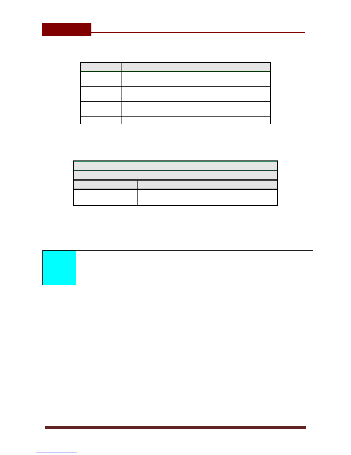
9.2.4 Table of parameters
Name
Comment
OS1
Mode of operation for output 1
OD1
Input 1 direct link to outputs
OD3
GSM network problem direct link to outputs
OD4
NAC direct link to outputs
OP1
Invert control for output 1
Table 5: Output management parameters
Example:
♦Direct programming on the SIM card
ICE-LOCK PROGRAMMING TABLE
SIM CARD PHONE BOOK
Name
Number
Description
OS1
14
Mono-stable pulse mode (14s pulse)
OD1
1
Input 1 activates output 1
OP1
1
Output 1 inverted
Table 6: Output management parameters example
♦Remote programming by SMS
;OS1=14;OD1=1;OP1=1;
9.3 DIRECT ACCESS BY ENTERING PIN ACCESS CODES
VIA ILLUMINATED KEYPAD
The user may control the predefined output by entering the PIN access codes. PIN
access code from 1 to 50 (PIN1 to PIN50) will activate the Output.
9.3.1 PIN1 to PIN50
PINx parameters are the PIN access codes for controlling the output.
ICE6LOCK$
INSTALLATION$MANUAL(
Page%18%
9.3.2 Table of parameters
Name
Comment
PIN1
PIN access code 1.
PIN2
PIN access code 2.
PIN3
PIN access code 3.
…
PIN48
PIN access code 48.
PIN49
PIN access code 49.
PIN50
PIN access code 50.
Table 7: Entering PIN access code parameters
Example:
♦Direct programming on the SIM card
ICE-LOCK PROGRAMMING TABLE
SIM CARD PHONE BOOK
Name
Number
Description
PIN1
3369
PIN access code 1.
PIN12
1234
PIN access code 12.
Table 8: Entering PIN access codes example
♦Remote programming by SMS
;PIN1=3369;PIN12=1234;
NOTE
PINx access codes must be 4 digits long, and must start with number
greater or equal 1.
9.3.3 Using the keypad for activating the Output – opening the doors
The user presses the 4 digit PIN access code and then presses the ’#’
key on the keypad to confirm the entry. If the code is correct, the output relay is
activated which triggers the electric lock, ramp, bollard, sliding doors, etc…
Example:
♦Typing the PIN access code on the keypad
For PIN1 type 3369 and press ’#’. If the code is correct you will
hear long beep confirmation, if the PIN access code is incorrect you
will hear 3 short beeps.
ICE6LOCK$
INSTALLATION$MANUAL(
Page%19%
9.4 SECURITY LEVEL - SL
SL parameter from 0 to 5 defines which telephone number stored in the phone
book from TN1 – TN5 can enter into programming and remote control of the ICE-
LOCK (dialing the ICE-LOCK phone number or sending the SMS).
NOTE
When the SL level is 0, an access to the ICE-LOCK is possible from any
phone!
IMPORTANT
Before any SL number is programmed the ICE-LOCK can accept
ALL CALLS. Remote SMS programming and remote controlling is
possible from any phone!
Name /
value
Comment
SL = 0
All calls and SMS are accepted
SL = 1
Only number stored under parameter TN1 has access
to unit
SL = 2
Numbers stored under parameters TN1 to TN2 have
access to unit
SL = 3
Numbers stored under parameters TN1 to TN3 have
access to unit
SL = 4
Numbers stored under parameters TN1 to TN4 have
access to unit
SL = 5
Numbers stored under parameters TN1 to TN5 have
access to unit
Table 9: SL parameter
Example:
♦Direct programming on the SIM card
ICE-LOCK PROGRAMMING TABLE
SIM CARD PHONE BOOK
Name
Number
Description
SL
3
No. stored under parameters TN1 to TN3 have
access to unit
Table 10: SL example

ICE6LOCK$
INSTALLATION$MANUAL(
Page%20%
♦Remote programming by SMS
;SL=3;
9.5 PREPAID CARD CREDIT AND VALIDITY INFORMATION
ICE-LOCK can be used with prepaid SIM cards and its limitations. To be able to
overcome this limitation of the prepaid SIM cards, ICE-LOCK offers the possibility
of automatic checking mechanism for credit and time expiration.
NOTE
ICE-LOCK automatically sends warning SMS when the credit reaches low
level defined by LCV parameter or SIM card validity is near to expiration.
NOTE
For support of different GSM providers contact support.
9.5.1 Programming prepaid card credit and validity string
To be able to support credit and time validity checking different parameters are
used.
9.5.1.1 LCV and SCV parameter
LCV is used to set the limit for low credit event. If the credit on prepaid SIM cards
falls below this limit SMS is send.
SCV the period of valid operating time varies with different GSM network
providers. The value can be programmed from 1 to 360 days. The default value
does not presume any kind of expiry warning.
For example in Slovenia SCV are 90 and in Italy 360 days
Table of contents
Other Transmitter Solutions Door Lock manuals


