EleMake S110BBL-F User manual

Smart Door Lock
S110BBL-F
FOR CUSTOMER SERVICE PLEASECALL:
(800)-315-9607
WWW.ELEMAKELOCKS.COM
Elemake keeps on working hard to provide customers top-grade
quality hardware at affordable price. Gracing customers’ doors
with stylish designs and excellent craftsmanship since 1976,
Elemake is always dedicated to making your life more safe and
stylish.

Series-ITD locks are a family of touch screen and fingerprint
internet deadbolts. They are ideal for residential homes,
apartment buildings, offices, schools, hospitals, and other
applications where restricted access to an area is needed.
All of ELEMAKE ITD series keyless deadbolt products come with
a 5 years’ warranty.
NOTE TO INSTALLER
Watching the videos are highly recommended, the video will
help the customer to understand the installation and functions
more easily.
Installation Video Linkage:
Functions Instruction Video Linkage:
FAILURE TO FOLLOW THESE INSTRUCTIONS COULD RESULT IN
DAMAGE TO THE PRODUCT AND VOID THE FACTORY WARRANTY
For Technical Assistance call Elemake at
1 (800)315-9607
QUICK SOLUTIONS TO COMMON PROBLEMS:

Initial Password:
123456

TABLE OF CONTENT
1. Warnings……………………………………………………………………………..2
2. Reset Lock To Factory Default...........................................................3
3. Introduction.....................................................................................4
3.1 Installation
(1) Step 1----Define the right-handed or left-handed door……5
(2) Step 2----Components and Tools…………………………………5
(3) Step 3----Prepare Deadbolt for Installation………….……....6
(4) Step 4 ---Install Deadbolt and door position
sensor ……..…………………………………………….………….7-8
4. Setting up.........................................................................................4
4.1 Steps to setup ..................................................................4
4.2 Add members ...................................................................4
4.3 Connect to Wifi .................................................................4
5. How to use the Elemake touchscreen deadbolt
3.2.1 Basic Functions(Local Operation) …………….……………9-10
3.2.2 Internet Functions………………………………………….....11-13
5. Trouble shooting................................................................................4
6. Quality Policy………………………………………………………………………….20
TABLE OF CONTENTS

1. WARNINGS
FCC: Class B Equipment
Series ITD series deadbolt has been tested and found to comply with the limits
for a Class B digital device---Part 15 of the FCC Rules. These limits are
purposed to provide protection against harmful interference in a residential
environment. The deadbolt generates, uses, and can radiate RF energy and, if
not installed and used as the instructions on users’manual, may have harmful
interference to radio communications. However, If this deadbolt does cause
harmful Interference to radio or television reception, which can be
determined by turning the deadbolt off and on, the user is encouraged to try
to correct the interference by one or more of the following measures:
• Relocate the radio communication devices’receiving antenna.
•Make separation between the deadbolt and receiver.
• Consult the customer service or professional radio/ technician for help.
.
2. RESET DEADBOLT TO FACTORY DEFAULT
The following procedure clears all the setting of the deadbolt, and returns the
deadbolt to default –deleting all user password/fingerprint/card.
2.1 RESET METHOD 1( see Figure A-1 to Figure A-4)
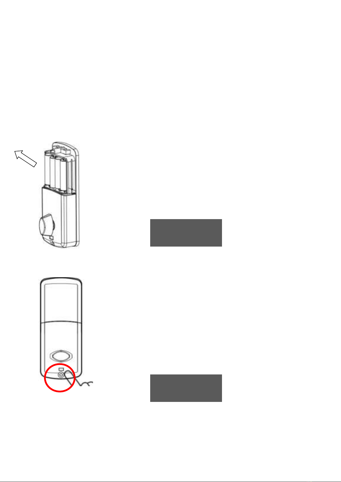
Figure A-1
Remove the batteries and wait
for 20 seconds,
Hold down the reset button
at the bottom of the inside
escutcheon
RESET BUTTON
Figure A-2

2.2 RESET METHOD 2( see Figure B-1)
This method is only for the family member who already
get the password/fingerprint enrolled(Please must keep
the door opened when doing the reset)
Install the batteries into the
inside escutcheon
Hold down the reset button
10-30s till voice says “reset
success”
Figure A-3
Figure A-4

Touch the screen with the back of
hand to activate the deadbolt,and
input 888 ,
The voice will remind family
member to input the enrolled
password or touch the fingerprint
for validation.
After validation, the deadbolt will be
reset till the voice says ”Reset
success”
Figure B-1
3. INSTALLATION
IMPORTANT THINGS INSTALLER NEED TO KNOW
PRIOR TO INSTALLATION
a. Initial password “123456”
b. Bolt Direction
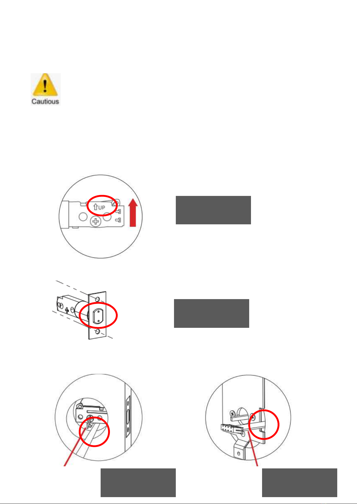
Please make sure the bolt is installed in correct direction according
to ”up”mark on the bolt. (see Figure C1)
c. The bolt must be in a retracted (unlocked) position when installing the
lockset. (see Figure C2)
d. The cable from the outside escutcheon should go under the bolt, (see
Figure C-3) and should go through the slot at the right side of the
mounting bracket. (see Figure C-4)
Figure C-1
Figure C-2
Figure C-3
Figure C-4
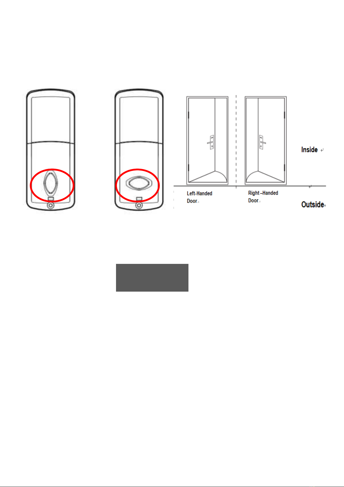
e. Thumb turn on inside escutcheon need to be turned to different
position for right handed door or left handed door in inside escutcheon
installation. (see Figure C-5)
f. Before installing the batteries, test the mechanical operation of the
lock by using
Both thumb turn and the key. The movement of the bolt should be
smooth and unobstructed. If operation is not smooth, review the
previous steps to ensure proper installation. (see Figure C-6)
Vertical Position
For Right Handed
Door
Horizontal Position
For Right Handed
Door
Figure C-5
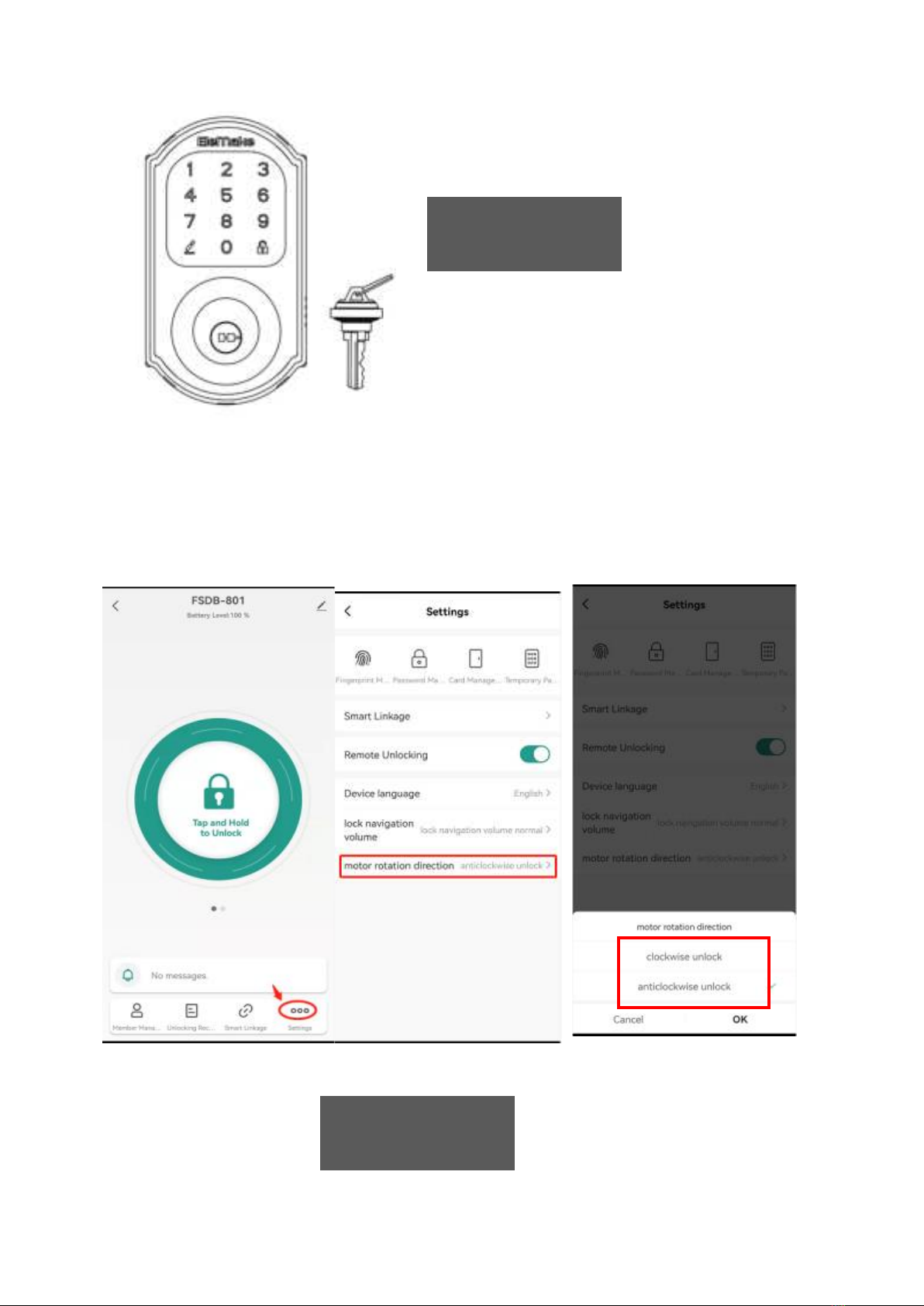
g. After the installation, connect the deadbolt to Smartlife APP, choose
the correct setting for door direction(setting>motor rotation
direction>clockwise unlock/counterclockwise unlock) (see Figure C-7)
Choose COUNTERCLOCKWISE for RIGHT HANDED DOOR
Choose CLOCKWISE for LEFT HANDED DOOR
Figure C-6
Figure C-7
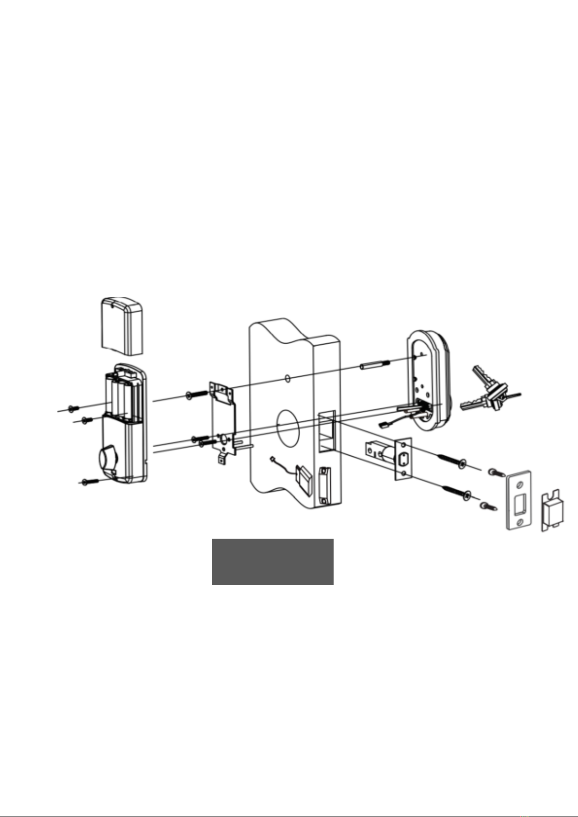
h. Assembly drawing(See Figure C-8)
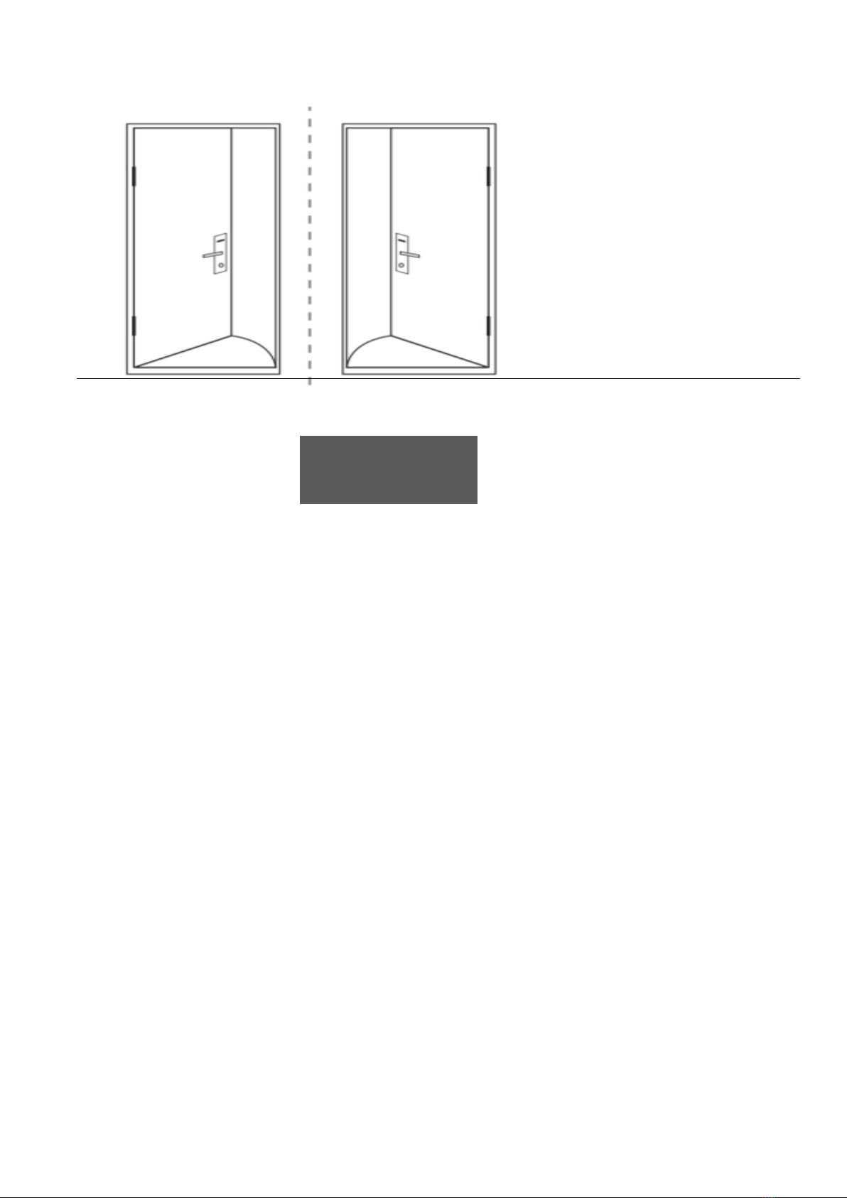
3.1 STEP 1----DEFINE THE RIGHT HANDED OR LEFT HANDED
DOOR.
To Ensure Proper Lock Handing and for an explanation of how to determine
your lock handing, please read this important note. (see Figure D-1)
Figure C-8
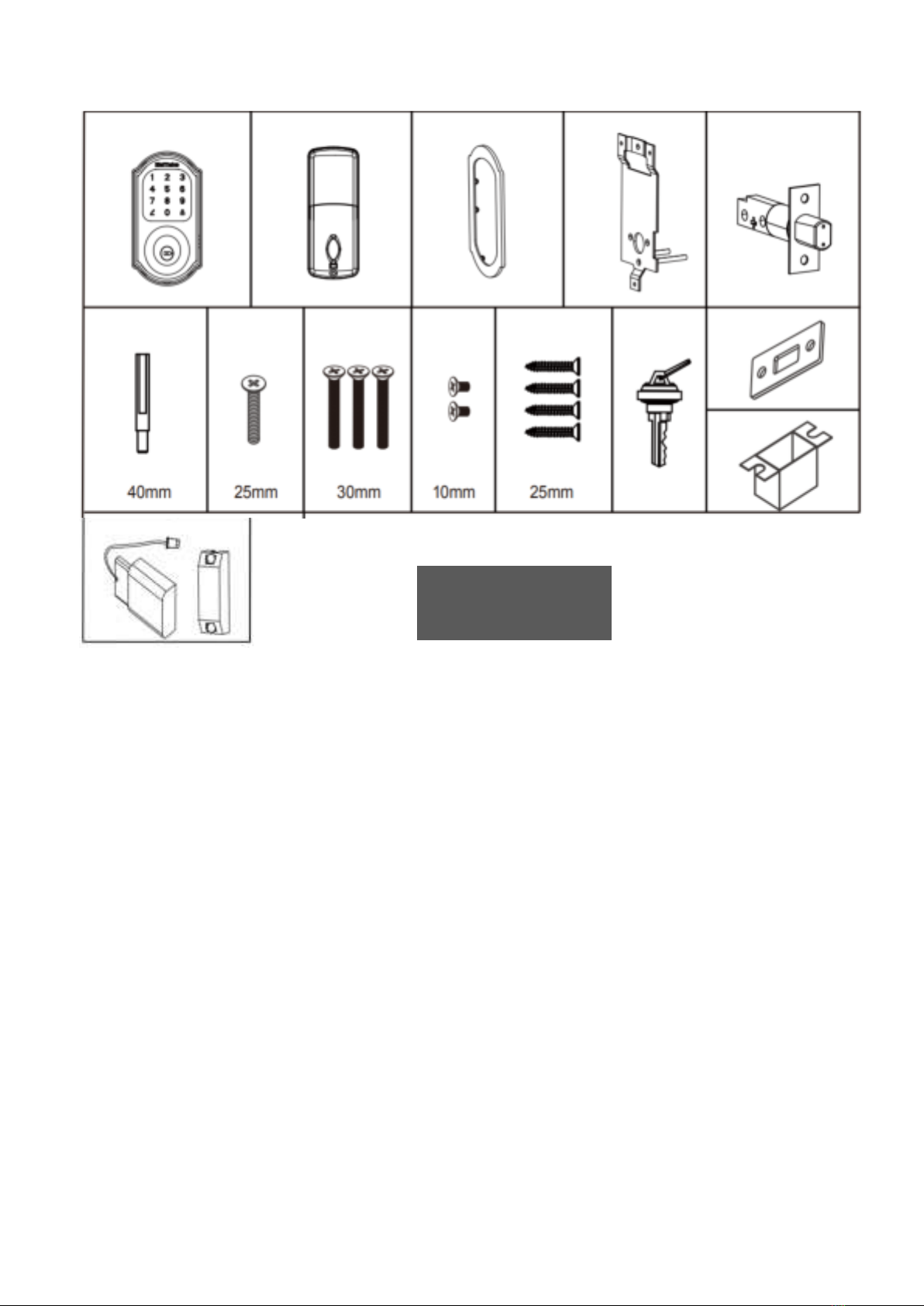
3.2 STEP 2----COMPONENTS AND TOOLS
(1) Components Included in the box
(see Figure E-1)
----
User’s manual
Outside Escutcheon
Bolt
Strike Plate
Screw Pack (see below)
Keys
Door Position Sensor(For automatic relocking--optional)
PARTS ILLUSTRATIONS
Inside
Outside
Left-Handed
Door
Right –Handed
Door
Figure 3I
Figure D-1
(2) Tools Needed
2-1/8" (54mm) hole saw
1" (26mm) boring bit
Wood screw drill bit
Chisel & hammer
3.3 STEP 3----PREPARE DEADBOLT FOR INSTALLATION
(1) Inside Escutcheon and back cover(see Figure F-1)
Figure E-1

(2) Mount Plate(See Figure F-2)
(3)Bolt
(See Figure F-3)
Use a pin to press down the
button to slide up the battery
cover to take off the batteries
This circled position is the wire
slot which will allow the cable
from the outside escutcheon to
go through in installation
Bolt can be adjusted to either
2-3/8 or 2-3/4 by twist the head
180 degree as above, and
Figure F-1
Figure F-2
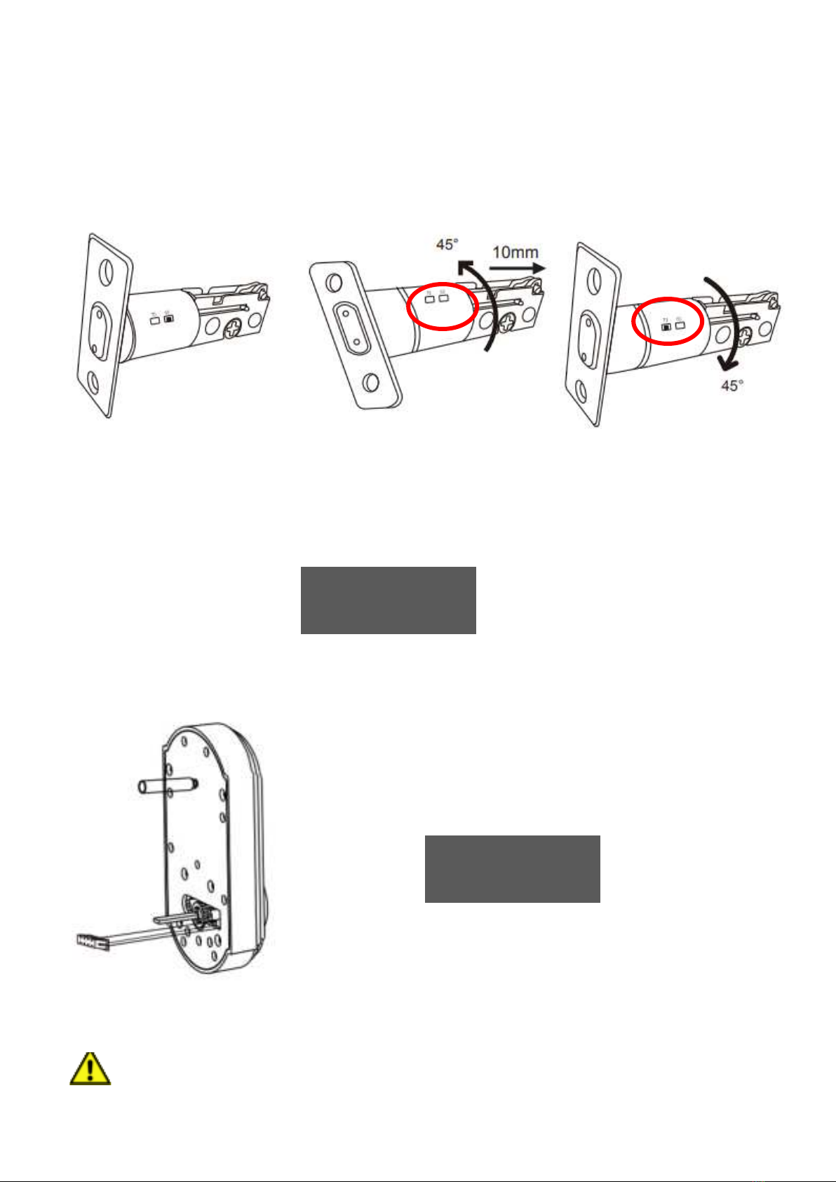
(4) Outside escutcheon
The outside escutcheon (with gasket) remains assembled(see Figure F-4).
3.4 STEP 4----INSTALL DEADBOLT & Door Position Sensor
(1) Install bolt in door.(see Figure G-4, Figure G-5, Figure G-6)
NOTE: THE BOLT MUST BE IN A RETRACTED (UNLOCKED) POSITION
PRIOR TO INSTALLING THE LOCKSET.(see Figure G-5)
Press small black button on
underside of bolt and pull to
extend to 2-3/4" backset
position.
Figure F-3
Figure F-4

Use 25mm wood screw to
secure the bolt onto the door.
Make sure the bolt stay upward
The bolt must be retracted
prior to installation
The spindle need to be in
vertical position in installation
Figure G-5
Figure G-4
(2) Install outside escutcheon(see Figure H-1, Figure H-2, Figure H-3,
Figure H-4)
NOTE: Cable goes UNDER the bolt(See Figure H-2)
Cable from outside escutcheon should go though the right
side slot of the mount bracket(See Figure H-4)
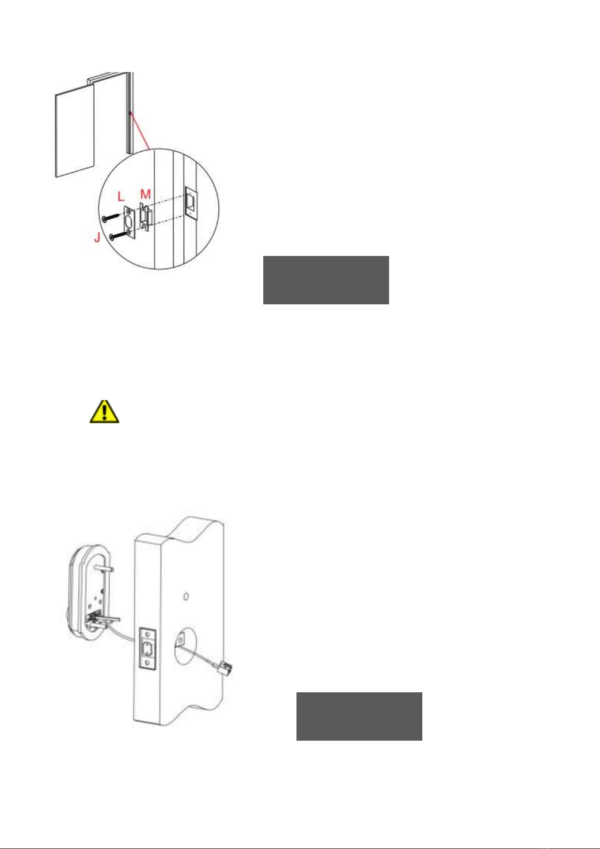
Install strike on the door
frame, making sure to
allow for the bolt to be
centered in the strike.
As you position the outside
escutcheon, route the cable
through 2-1/8" diameter hole(The
cable must go under the bolt)
Figure G-6
Figure H-1

The cable need to go under
the bolt in installation
Holding the outside escutcheon flush
to the door, position the inside
mounting plate by first routing the
cable and connector through the
mounting plate's wire slot on the side
Insert the mounting plate “tongue” into
the bottom slot of the outside
escutcheon
Secure both assemblies using (2)40mm
machine screws
Figure H-2
Figure H-3

(3) Route cable(see Figures I-1 and Figure I-2, Figure I-3).
(a) Attach cable assembly to the inside escutcheon printed circuit board
(PCB) by lining up notches on top of cable connector to slots on PCB
connector (Figure 3K). Press connector in firmly using thumbs until
completely seated (proper position indicated by arrows on PCB as in
(see Figures I-1 and Figure I-2, Figure I-3).
(b) If need automatic relocking function, need to install the door position
sensor(supplied in the box), attach the sensor cable to the inside
escutcheon printed circuit board (PCB), the cable route through the
slot on the rubber gasket. (see Figures I-1 and Figure I-2).
Cable from outside escutcheon
should go though the right side slot
of the mount bracket
Cable and connector for door
position sensor (Optional for
automatic relocking)
Outside escutcheon cable and
connector
Figure H-4
Figure I-1
Table of contents
Other EleMake Door Lock manuals

Popular Door Lock manuals by other brands


Assa Abloy
Assa Abloy 1125 Series Mounting instruction

Lockly
Lockly LATCH EDITION SECURE PGD628 installation guide

Assa Abloy
Assa Abloy shine user guide

Command access
Command access ARLP-UL-M-KIT Insert Instructions

Connective Touch
Connective Touch FLEXI User guide lines

Assa Abloy
Assa Abloy Lockwood Standalone User manual and instructions

Samsung
Samsung Ezon SHS-3120 user guide

Toledo
Toledo V160ELPLUUS15 quick start guide

Assa Abloy
Assa Abloy Sargent Harmony Series installation instructions

DynaLock
DynaLock 3101C installation instructions

Water Street
Water Street Mortise Passage Set installation instructions

Schlage
Schlage LE162 Installation instructions & user guide