manuals.online logo
Brands
  1. Home
  2. •
  3. Brands
  4. •
  5. Siemens
  6. •
  7. Industrial Equipment
  8. •
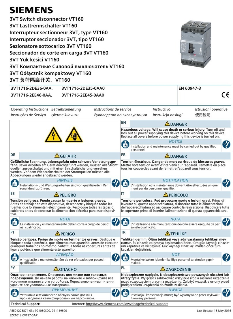
  9. Siemens SIMATIC RF290R Instruction sheet

Siemens SIMATIC RF290R Instruction sheet

RF290R
___________________
___________________
___________________
___________________
___________________
___________________
___________________
___________________
___________________
___________________
___________________
SIMATIC Ident
RF290R
Configuration Manual
09/2014
C79000
-G8976-C377-01
Introduction
1
Description
2
Data transmission between
RF290R and host
3
Serial data format and
protocol frames
4
Configuration parameters
(CFG)
5
Protocols for the
configuration of the reader
6
Protocols for controlling the
reader
7
Protocols for
ISO 15693 host commands
8
ISO 15693 host commands
9
Protocols for the
Buffered Read Mode
10
Appendix
A
Siemens AG
Industry Sector
Postfach 48 48
90026 NÜRNBERG
GERMANY
C79000-G8976-C377-01
Ⓟ
09/2014 Subject to change
Copyright © Siemens AG 2014.
All rights reserved
Legal information
Warning notice system
This manual contains notices you have to observe in order to ensure your personal safety, as well as to prevent
damage to property. The notices referring to your personal safety are highlighted in the manual by a safety alert
symbol, notices referring only to property damage have no safety alert symbol. These notices shown below are
graded according to the degree of danger.
DANGER
indicates that death or severe personal injury will result if proper precautions are not taken.
WARNING
indicates that death or severe personal injury may result if proper precautions are not taken.
CAUTION
indicates that minor personal injury can result if proper precautions are not taken.
NOTICE
indicates that property damage can result if proper precautions are not taken.
If more than one degree of danger is present, the warning notice representing the highest degree of danger will
be used. A notice warning of injury to persons with a safety alert symbol may also include a warning relating to
property damage.
Qualified Personnel
The product/system described in this documentation may be operated only by
personnel qualified
for the specific
task in accordance with the relevant documentation, in particular its warning notices and safety instructions.
Qualified personnel are those who, based on their training and experience, are capable of identifying risks and
avoiding potential hazards when working with these products/systems.
Proper use of Siemens products
Note the following:
WARNING
Siemens products may only be used for the applications described in the catalog and in the relevant technical
documentation. If products and components from other manufacturers are used, these must be recommended
or approved by Siemens. Proper transport, storage, installation, assembly, commissioning, operation and
maintenance are required to ensure that the products operate safely and without any problems. The permissible
ambient conditions must be complied with. The information in the relevant documentation must be observed.
Trademarks
All names identified by ® are registered trademarks of Siemens AG. The remaining trademarks in this publication
may be trademarks whose use by third parties for their own purposes could violate the rights of the owner.
Disclaimer of Liability
We have reviewed the contents of this publication to ensure consistency with the hardware and software
described. Since variance cannot be precluded entirely, we cannot guarantee full consistency. However, the
information in this publication is reviewed regularly and any necessary corrections are included in subsequent
editions.
RF290R
Configuration Manual, 09/2014, C79000-G8976-C377-01 3
Table of contents
1 Introduction............................................................................................................................................. 7
1.1 Preliminary information .............................................................................................................7
1.2 General information and abbreviations/acronyms ....................................................................7
2 Description.............................................................................................................................................. 9
2.1 Safety notes ..............................................................................................................................9
3 Data transmission between RF290R and host....................................................................................... 11
3.1 Configuration and control commands .....................................................................................11
3.2 ISO 15693 host commands ....................................................................................................12
3.3 Buffered Read Mode...............................................................................................................16
3.4 Scan Mode..............................................................................................................................17
4 Serial data format and protocol frames.................................................................................................. 19
4.1 CRC16 calculation algorithm ..................................................................................................20
5 Configuration parameters (CFG) ........................................................................................................... 21
5.1 CFG0: Passwords...................................................................................................................22
5.2 CFG1: COM interface .............................................................................................................23
5.3 CFG2: Inputs / outputs............................................................................................................26
5.4 CFG3: RF interface.................................................................................................................27
5.5 CFG4: Transponder parameters.............................................................................................28
5.6 CFG5: Anticollision .................................................................................................................30
5.7 CFG6: Chip-specific commands .............................................................................................30
5.8 CFG7-10: Reserved................................................................................................................31
5.9 CFG11: Read mode - read data .............................................................................................31
5.10 CFG12: Read mode - filter......................................................................................................34
5.11 CFG13: Scan Mode ................................................................................................................35
5.12 CFG14: Reserved ...................................................................................................................38
5.13 CFG15: Antenna multiplexing.................................................................................................38
5.14 CFG16: Reset persistency......................................................................................................39
5.15 CFG17: Reserved ...................................................................................................................40
5.16 CFG18-19: Reserved..............................................................................................................40
5.17 CFG20: RF parameters ..........................................................................................................41
5.18 CFG21-63: Reserved..............................................................................................................42
Table of contents
RF290R
4Configuration Manual, 09/2014, C79000-G8976-C377-01
6 Protocols for the configuration of the reader .......................................................................................... 43
6.1 [0x80] Read Configuration ..................................................................................................... 43
6.2 [0x81] Write Configuration ..................................................................................................... 44
6.3 [0x83] Set Default Configuration (Reset) ............................................................................... 45
7 Protocols for controlling the reader........................................................................................................ 47
7.1 [0x52] Baud Rate Detection ................................................................................................... 47
7.2 [0x63] RF-Controller Reset .................................................................................................... 48
7.3 [0x64] System Reset.............................................................................................................. 48
7.4 [0x66] Get Reader Info........................................................................................................... 49
7.5 [0x69] RF Reset ..................................................................................................................... 51
7.6 [0x6A] RF Output ON/OFF..................................................................................................... 52
7.7 [0x6D] Get Noise Level .......................................................................................................... 53
7.8 [0x6E] Reader Diagnostic ...................................................................................................... 53
7.9 [0x72] Set Output ................................................................................................................... 55
7.10 [0x74] Get Input...................................................................................................................... 56
7.11 [0x85] Set System Timer........................................................................................................ 57
7.12 [0x86] Get System Timer ....................................................................................................... 57
7.13 [0xA0] Reader-Login .............................................................................................................. 59
8 Protocols for ISO 15693 host commands .............................................................................................. 61
8.1 [0xB0] Host commands for mandatory commands according to ISO 15693 and
optional commands ................................................................................................................ 61
8.2 [0x01] Inventory...................................................................................................................... 61
8.3 [0x02] Stay Quiet.................................................................................................................... 63
8.4 [0x22] Lock Multiple Blocks.................................................................................................... 64
8.5 [0x23] Read Multiple Blocks................................................................................................... 65
8.6 [0x24] Write Multiple Blocks................................................................................................... 67
8.7 [0x25] Select .......................................................................................................................... 68
8.8 [0x26] Reset to Ready .......................................................................................................... 69
8.9 [0x27] Write AFI ..................................................................................................................... 70
8.10 [0x28] Lock AFI ...................................................................................................................... 71
8.11 [0x29] Write DSFID ................................................................................................................ 71
8.12 [0x2A] Lock DSFID ................................................................................................................ 72
8.13 [0x2B] Get System Information .............................................................................................. 73
8.14 [0x2C] Get Multiple Block Security Status ............................................................................. 75
Table of contents
RF290R
Configuration Manual, 09/2014, C79000-G8976-C377-01 5
9 ISO 15693 host commands ................................................................................................................... 77
9.1 [0xBF] Transparent command according to ISO 15693 .........................................................77
9.2 Supported ISO 15693 host command for ISO 15693 transponders.......................................79
9.2.1 EM Microelectronics (EM4034)...............................................................................................79
9.2.2 EM Microelectonics (EM4135)................................................................................................80
9.2.3 Fujitsu (MB89R116) ................................................................................................................81
9.2.4 Fujitsu (MB89R118) ................................................................................................................82
9.2.5 Fujitsu (MB89R119) ................................................................................................................83
9.2.6 Infineon (ISO address mode) 0xE0 ........................................................................................84
9.2.7 Infineon (My-d-Light)...............................................................................................................85
9.2.8 NXP (I-Code SLI) ....................................................................................................................86
9.2.9 NXP (I-Code SLI-S) ................................................................................................................86
9.2.10 NXP (I-Code SLI-L).................................................................................................................87
9.2.11 NXP (I-Code SLIX)..................................................................................................................88
9.2.12 NXP (I-Code SLIX-S)..............................................................................................................89
9.2.13 NXP (I-Code SLIX-L) ..............................................................................................................90
9.2.14 STMicroelectronics (LRI64) ....................................................................................................91
9.2.15 STMicroelectronics (LRI2k, LRIS2k).......................................................................................92
9.2.16 STMicroelectronics (M24LR64-R) ..........................................................................................93
9.2.17 Texas Instruments (Tag-it HFI Pro / Standard) ......................................................................94
9.2.18 Texas Instruments (Tag-it HFI Plus).......................................................................................95
10 Protocols for the Buffered Read Mode................................................................................................... 97
10.1 Sequence in Buffered Read Mode..........................................................................................97
10.2 Transponder access in Buffered Read Mode .........................................................................98
10.3 [0x22] Read Buffer ..................................................................................................................98
10.4 [0x31] Read Data Buffer Info ................................................................................................100
10.5 [0x32] Clear Data Buffer .......................................................................................................101
10.6 [0x33] Initialize Buffer............................................................................................................102
A Appendix............................................................................................................................................. 103
A.1 Codes of the transponder types............................................................................................103
A.2 Time response of the asynchronous interface......................................................................103
A.3 Time response for ISO 15693 host commands ....................................................................103
A.4 Index of the status bytes .......................................................................................................104
A.5 Error codes of the transponders ...........................................................................................107
A.6 LED functions........................................................................................................................107
A.7 Example of read data............................................................................................................108
A.8 Service & Support.................................................................................................................109
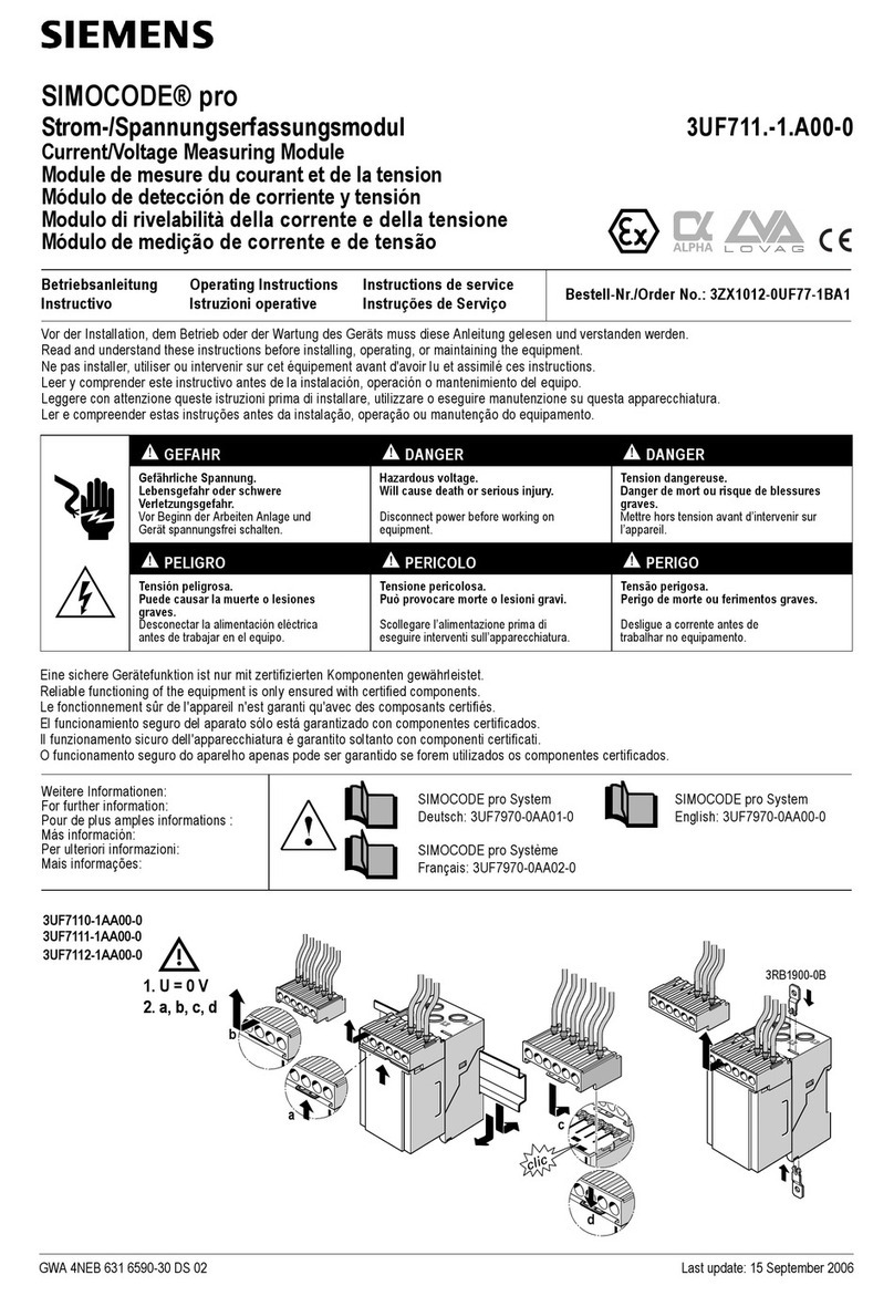
Table of contents
RF290R
6Configuration Manual, 09/2014, C79000-G8976-C377-01
RF290R
Configuration Manual, 09/2014, C79000-G8976-C377-01 7
Introduction
1
1.1
Preliminary information
Purpose of this documentation
This documentation provides you with an overview of the configuration, parameter
assignment and programming of the RF290R reader. The programming manual is intended
for users and programmers involved in configuration, commissioning and servicing of the
RF290R.
To configure the RF290R, you require knowledge of the following:
●Structure of the system (e.g. components used, in particular the transponders)
●Basic knowledge of RFID
Range of validity of this documentation
This documentation is valid for all supplied variants of the RF290R and describes the
RF290R as delivered from March 2013 onwards.
Registered trademarks
SIMATIC ®, SIMATIC RF ®, MOBY ®, RF-MANAGER ® and SIMATIC Sensors ® are
registered trade marks of Siemens AG.
1.2
General information and abbreviations/acronyms
General information on this document
●If individual bits in a byte are shown as "-", the bit positions are reserved for future
expansion or for internal test and manufacturing functions. These bit positions must not
be changed since this can cause incorrect operation of the reader.
●The following number formats are used:
–0...9: for decimal numbers
–0x00...0xFF: for hexadecimal numbers
–b0...1: for binary numbers
●The hexadecimal value in brackets "[ ]" indicates a control byte (command).
Introduction
1.2 General information and abbreviations/acronyms
RF290R
8Configuration Manual, 09/2014, C79000-G8976-C377-01
Abbreviations/acronyms used
ADR
Address
Address
ASK
Amplitude Shift Keying
CB
Config Block
Configuration Block
CFG
Configuration Parameter Block
CRC Cyclic Redundancy Check Cyclic Redundancy Check
DB
Data Block
Data block
FIFO
First In First Out
First in - first out
frq
Frequency
Frequency
FSK
Frequency Shift Keying
h
Hour
Hour
Hz
Hertz
Hertz
ID
Identification
Identifier
IN
Input
Input
LEN
Length
Length
LOC
Location
Location
LSB
Least Significant Byte
Least significant byte
min
Minutes
Minutes
ms
Milliseconds
Milliseconds
MSB
Most Significant Byte
Most significant byte
N
Number
Number
OUT
Output
Output
R/W
Read/Write Access
Read and write access
RD
Read
Read
REL Relay Relay
RF
Radio Frequency
Radio frequency
RO
Read Only Acess
Read-only access
RSSI
Received Signal Strength Indicator
RTC
Real Time Clock
Real-time clock
TAB
Table
Table
TR
Transponder
Transponder
TS
Timeslot
Time slot
UID Unique Identifier (read only Serial Num-
ber)
Unique Identifier (read-only serial num-
ber)
WO
Write Only Access
Write-only access
WR
Write
Write
RF290R
Configuration Manual, 09/2014, C79000-G8976-C377-01 9
Description
2
The RF290R is the most powerful reader of the SIMATIC RF200 product series. The reader
can directly control antenna multiplexing functions to be able to handle complex antenna
adjustments in different gate and portal configurations.
The RF290R can be operated in two different main modes:
●SIMATIC mode (RS-422 interface, protocol 3964R) e.g. with FB/FC 45
●PC mode (RS-232 interface, extended protocol in ISO host mode)
The selection of the main mode is decided by the interface cable used.
Note
This manual only describes the main mode PC mode.
You will find further information on the SIMATIC mode in the manuals of the relevant function
blocks in "Industry online support
(
http://support.automation.siemens.com/WW/view/en/10805817)".
2.1
Safety notes
WARNING
Note for wearers of heart pacemakers
Even if this device does not exceed the valid limit values for electromagnetic fields, you
should keep a minimum distance of 25 cm between the antenna and your pacemaker and
should not remain for longer periods of time in the immediate vicinity of the device or
antenna.
CAUTION
Unauthorized modifications and the use of spare parts and additional devices
Unauthorized modifications and the use of spare parts and additional devices not sold or
recommended by the manufacturer can cause fire, electric shock or injury. No liability
whatsoever will be accepted if such unauthorized measures are taken.
Description
2.1 Safety notes
RF290R
10 Configuration Manual, 09/2014, C79000-G8976-C377-01
NOTICE
Notes on liability
The liability provisions of the manufacturer valid at the time of purchase apply to the device.
The manufacturer cannot be made legally responsible for inaccuracies, errors or omissions
in the manual or automatically set parameters for a device or for incorrect use of a device.
NOTICE
Use adhering to the regulations
The use of the device and its installation must be in keeping with national legal regulations
and local electrical regulations.
When working on devices, the valid safety regulations must be adhered to.
RF290R
Configuration Manual, 09/2014, C79000-G8976-C377-01 11
Data transmission between RF290R and host
3
There are five different types of data transmission between the RF290R and the host
(terminal or PC). The ISO 15693 host commands, the "Buffered Read Mode" and the "Scan
Mode" are used to exchange data between the reader and host. The configuration
commands and the control commands of the reader are used to adapt the reader
parameters to the individual application.
The following types of communication are supported by the asynchronous interface:
●Configuration commands
●Control commands of the reader
●ISO 15693 host commands
●Buffered Read Mode
●Scan Mode
3.1
Configuration and control commands
This type of data transmission is suitable for configuration and diagnostics of the reader via
the asynchronous interface.
The configuration parameters of the reader are stored in its memory. To retain the
configuration data when the device is turned off, this must be stored in the EEPROM. When
it is turned on again, the reader reads the configuration from the EEPROM.
The reader control is executed immediately. The response of the reader contains status or
data information of the command.
Figure 3-1 Sequence of the configuration and control commands
Data transmission between RF290R and host
3.2 ISO 15693 host commands
RF290R
12 Configuration Manual, 09/2014, C79000-G8976-C377-01
3.2
ISO 15693 host commands
The ISO 15693 host commands are a method of transferring data between the host and
transponders using the reader. To allow this, the transponders must be in the antenna field
of the reader.
Note
If you write data to a transponder, you need to make sure that the transponder remains in
the antenna field of the reader dur
ing the entire write procedure. If the transponder leaves
the antenna field of the reader during the write access, this results in loss of data. In this
case, an error message to this effect is displayed.
The reader distinguishes three modes:
Addressed mode
Before data can be read or written in the addressed mode, the UID of the transponder must
be known. You can obtain the UID by sending the command "[0x01] Inventory". If there is a
transponder in the antenna field of the reader at this moment, it replies with its UID. For all
subsequent read and write commands the transponder must be addressed with the correct
UID.
The following graphics show the necessary steps for communication with a transponder in
the addressed mode.
Figure 3-2 Sequence when calling up the UID in the addressed mode
Data transmission between RF290R and host
3.2 ISO 15693 host commands
RF290R
Configuration Manual, 09/2014, C79000-G8976-C377-01 13
Figure 3-3 Sequence when reading in the addressed mode
Figure 3-4 Sequence when writing in the addressed mode
Non-addressed mode
In the non-addressed mode, you do not need to know the UID of the transponder. This mode
is useful if there is only one transponder in the antenna field of the reader.
The following graphics show the necessary steps for communication with a transponder in
the non-addressed mode.
Figure 3-5 Sequence when reading in the non-addressed mode
Data transmission between RF290R and host
3.2 ISO 15693 host commands
RF290R
14 Configuration Manual, 09/2014, C79000-G8976-C377-01
Figure 3-6 Sequence when writing in the non-addressed mode
Selected mode
In this mode, the reader communicates only with the one selected transponder.
Before data can be read or written in the selected mode, the UID of the transponder must be
known. You can obtain the UID by sending the command "[0x01] Inventory". In a second
step, the transponder must be selected with the command "[0x25] Select". This must include
the UID of the transponder.
The following graphics show the necessary steps for communication with a transponder in
the selected mode.
Figure 3-7 Sequence when calling up the UID in the selected mode
Data transmission between RF290R and host
3.2 ISO 15693 host commands
RF290R
Configuration Manual, 09/2014, C79000-G8976-C377-01 15
Figure 3-8 Sequence when selecting the UID in the selected mode
Figure 3-9 Sequence when reading in the selected mode
Figure 3-10 Sequence when writing in the selected mode
Data transmission between RF290R and host
3.3 Buffered Read Mode
RF290R
16 Configuration Manual, 09/2014, C79000-G8976-C377-01
3.3
Buffered Read Mode
The "Buffered Read Mode" is a mode used to detect transponders in the antenna field of the
reader. In the "Buffered Read Mode", all transponder data is filtered according to the setting
to minimize the amount of data transmitted between reader and host. The "Buffered Read
Mode" is controlled using the following commands:
●"0x22 Read Buffer"
●"0x32 Clear data Buffer"
●"0x33 Initialize Buffer"
You will find further information on the commands in the "Buffered Read Mode" in the section
"Protocols for the Buffered Read Mode (Page 97)".
In this mode, the reader automatically selects the transponders within its antenna field and
reads the required data. The transponder data that is read out is stored in a FIFO data
buffer.
The transponder data that has been read out can be read with the command "[0x22] Read
Buffer". This command reads the first available data set from the data buffer. If you have
already read data, you first need to delete this with the command "[0x32] Clear Data Buffer"
before you can fetch the next data record from the buffer with the read command.
If the "Buffered Read Mode" is activated in the configuration block " CFG1: Interface" the
reader starts to read transponder data immediately after it is turned on. The "Buffered Read
Mode" can be re-initialized with the command "[0x33] Initialize Buffer".
In the "Buffered Read Mode", the reader responds to every valid message with a data or
status protocol. The response also contains the control byte that the reader has received.
Figure 3-11 Sequence when reading in Buffered Read Mode
Data transmission between RF290R and host
3.4 Scan Mode
RF290R
Configuration Manual, 09/2014, C79000-G8976-C377-01 17
Figure 3-12 Sequence when deleting in Buffered Read Mode
Note
Note the following information about the "Buffered Read Mode":
•
In "Buffered Read Mode", only read operations are possible.
•
The "Buffered Read Mode" can only be used when the "Scan Mode" is turned off.
3.4
Scan Mode
In this mode the reader sends data unsolicited to the host as soon as there is a transponder
in the antenna field and it was possible to read valid data.
If "Scan Mode" is set, the content of the message block (UID, data block) can be adapted to
any user application. The "Scan Mode" can be used with the asynchronous interface.
The reader begins with the output of the protocol block as soon as all required data has been
read correctly from the transponder. If the reader cannot read all data of a protocol block
completely and free of errors, it does not output any data. If, for example, the address of the
data block is invalid, the UID of the transponder is not sent.
Scan mode via the asynchronous interface
The data is output depending on its configuration according to the following scheme. The
specified order cannot be changed.
The format of the protocols sent depends on the configuration and number of transponders
in the antenna field of the reader.
Example 1:
There is one transponder in the antenna field. The UID and data block are to be read:
Data transmission between RF290R and host
3.4 Scan Mode
RF290R
18 Configuration Manual, 09/2014, C79000-G8976-C377-01
Example 2:
There are three transponders in the antenna field. Only the UID is to be read:
PR
UID1
EC
UID2
EC
UID3
EC
Example 3:
There are three transponders in the antenna field. Only the data block is to be read:
PR
Data1
EC
Data2
EC
Data3
EC
Example 4:
There are two transponders in the antenna field. The UID and data block are to be read:
PR
UID1
SC
Data1
EC
UID2
SC
Data2
EC
Description of the parameters
●PR
Communications prefix (optional)
●UID
Serial number (fixed)
●Data
Data blocks (freely programmable)
●SC
Separator (optional)
●EC
End character (optional)
●ts
SCAN-LOCK-TIME
●tr
Time until the next new read out of the transponder
Note
Note the following information about the "Scan Mode":
•
If the "Scan Mode" is activated, configuration protocols should only be sent to the reader
when there is no transponder in the antenna field of the reader.
•
In "Scan Mode", only read operations are possible.
RF290R
Configuration Manual, 09/2014, C79000-G8976-C377-01 19
Serial data format and protocol frames
4
The communication between the reader and connected host (terminal, PC etc.) is handled
according to a specified protocol. The protocol used is suitable for use on a data bus and
includes a bus address.
The reader only supports the extended protocol frame (not compatible with the simple
protocol frame of the SLG D10). When the host application sends a protocol frame, the
reader always responds with a protocol frame.
With data transfer via the asynchronous interface, the reader returns the requested data or a
status byte. The response contains the transferred control byte. If a bad protocol frame is
transferred, the reader does not respond.
Protocol frame
Table 4- 1 Host → reader
Byte
1
2
3
4
5
(6 ... (n-2))
(n-1)
n
Content
STX MSB
ALENGTH
LSB
ALENGTH
COM-ADR CONTROL-
BYTE
(DATA) LSB
CRC16
MSB
CRC16
Default
0x02
-
-
-
-
-
-
-
Table 4- 2 Host ← reader
Byte
1
2
3
4
5
6
(7 ... (n-2))
(n-1)
n
Content
STX MSB
ALENGTH
LSB
ALENGTH
COM-
ADR
CONTRO
L-BYTE
STATUS (DATA) LSB
CRC16
MSB
CRC16
Default
0x02
-
-
-
-
-
-
-
-
Table 4- 3 Description of the protocol byte
Function
Description
STX
If the response protocol of the reader starts with the character STX (0x02), the
protocol frame has the extended protocol length. In this case, the protocol length
is specified by the 2-byte parameter ALENGTH.
ALENGTH
(n = 8...65535)
Number of protocol bytes including STX, ALENGTH and CRC16
COM-ADR
0..254 address of the device in bus mode
The reader can be addressed at any time using COM-ADR 255.
CONTROL-BYTE
Defines the command that the reader is to execute.
STATUS
1)
Includes the status message or protocol data from or to the reader.
Serial data format and protocol frames
4.1 CRC16 calculation algorithm
RF290R
20 Configuration Manual, 09/2014, C79000-G8976-C377-01
Function
Description
DATA
Is an optional data field with a variable length. The number of the DATA byte
depends on the command. The data is always sent first as MSB if the reader is
in the ISO host command mode.
CRC16
Cyclic redundancy check of the protocol bytes of 1 to n-2, as specified by
CCITT-CRC16
•Polynomial: x16 + x12 + x5+ 1 (0x8408)
•Start value: 0xFFFF
•Direction: Backward
1) You will find further information on STATUS in the appendix "Index of the status bytes
(Page 104)".
Data format
●Baud rate: 38,400 (default)
●Data bits: 8
●Stop bits: 1
●Parity:
–even (default)
–odd
–none
4.1
CRC16 calculation algorithm
Polynomial:
x
16
+ x
12
+ x
5
+ 1
⇒ CRC_POLYNOM = 0x8408;
Start value:
0xFFFF
⇒ CRC_PRESET = 0xFFFF;
Example in C:
unsigned int crc = CRC_PRESET;
for (i = 0; i < cnt; i++)
/* cnt = number of protocol bytes without CRC */
{
crc ^= DATA[i];
for (j = 0; j < 8; j++)
{
if (crc & 0x0001)
crc = (crc >> 1) ^ CRC_POLYNOM;
else
crc = (crc >> 1);
}
}

Other Siemens Industrial Equipment manuals

Siemens SIMATIC NET SCALANCE M-800 User manual

Siemens

Siemens SIMATIC NET SCALANCE M-800 User manual

Siemens SIVACON S 8PQ Series User manual

Siemens

Siemens SIVACON S 8PQ Series User manual

Siemens SIMATIC PROFINET User manual

Siemens

Siemens SIMATIC PROFINET User manual

Siemens DMA1104D User manual

Siemens

Siemens DMA1104D User manual

Siemens SIRIUS 3RV1923 User manual

Siemens

Siemens SIRIUS 3RV1923 User manual

Siemens 7VE51 User manual

Siemens

Siemens 7VE51 User manual

Siemens SIVACON S4-ALPHA Product guide

Siemens

Siemens SIVACON S4-ALPHA Product guide

Siemens SIMOGEAR 2730 Service manual

Siemens

Siemens SIMOGEAR 2730 Service manual

Siemens SINAMICS G120P User manual

Siemens

Siemens SINAMICS G120P User manual

Siemens SIVACON 8PS BD2 Series User manual

Siemens

Siemens SIVACON 8PS BD2 Series User manual

Siemens SIVACON 8PS BD2 Series User manual

Siemens

Siemens SIVACON 8PS BD2 Series User manual

Siemens SINUMERIK 840D sl Parts list manual

Siemens

Siemens SINUMERIK 840D sl Parts list manual

Siemens SIMATIC ET 200SP User manual

Siemens

Siemens SIMATIC ET 200SP User manual

Siemens SIMATIC IPC User manual

Siemens

Siemens SIMATIC IPC User manual

Siemens SIMATIC HMI User manual

Siemens

Siemens SIMATIC HMI User manual

Siemens SIWAREX WL260 SP-S AA User manual

Siemens

Siemens SIWAREX WL260 SP-S AA User manual

Siemens 3WN6 User manual

Siemens

Siemens 3WN6 User manual

Siemens SIRIUS 3RT2.1 2 Series User manual

Siemens

Siemens SIRIUS 3RT2.1 2 Series User manual

Siemens 3VA9687-0GK00 User manual

Siemens

Siemens 3VA9687-0GK00 User manual

Siemens GCP5000 User manual

Siemens

Siemens GCP5000 User manual

Siemens Reyrolle 7SR5 User manual

Siemens

Siemens Reyrolle 7SR5 User manual

Siemens SIMATIC S7-1500R/H User manual

Siemens

Siemens SIMATIC S7-1500R/H User manual

Siemens SIRIUS 3RA142-8XB20 Series User manual

Siemens

Siemens SIRIUS 3RA142-8XB20 Series User manual

Siemens SIMATIC RTLS4083T User manual

Siemens

Siemens SIMATIC RTLS4083T User manual

Popular Industrial Equipment manuals by other brands

Eaton CoviO installation instructions

Eaton

Eaton CoviO installation instructions

BOCI BLT520H product manual

BOCI

BOCI BLT520H product manual

Ammeraal Beltech uni chains uni NTB Series Instructions and installation

Ammeraal Beltech

Ammeraal Beltech uni chains uni NTB Series Instructions and installation

JAUDT DS 6108 Translation of the original operating instructions

JAUDT

JAUDT DS 6108 Translation of the original operating instructions

ABB HT569793 Operation manual

ABB

ABB HT569793 Operation manual

SPX APV ParaFlow instruction manual

SPX

SPX APV ParaFlow instruction manual

SMC Networks MHZ2-6C-M9PLS Operation manual

SMC Networks

SMC Networks MHZ2-6C-M9PLS Operation manual

Laars ProtoNode FPC-N54 Installation and operating manual

Laars

Laars ProtoNode FPC-N54 Installation and operating manual

System air KBR 280DV Installation and operating instructions

System air

System air KBR 280DV Installation and operating instructions

Avantco Backhoe 170 Operator's manual

Avantco

Avantco Backhoe 170 Operator's manual

DESSALATOR FREEDOM DC 60 Assembly and user's manual

DESSALATOR

DESSALATOR FREEDOM DC 60 Assembly and user's manual

Kval 700-DC Operation and service manual

Kval

Kval 700-DC Operation and service manual

Napa Carlyle Tools 791-6005A operating manual

Napa

Napa Carlyle Tools 791-6005A operating manual

Leader Evaporator WSE manual

Leader Evaporator

Leader Evaporator WSE manual

Festo EGC-BS-KF Series operating instructions

Festo

Festo EGC-BS-KF Series operating instructions

ABB HT606449 Operation manual

ABB

ABB HT606449 Operation manual

Eaton R-Frame Series installation instructions

Eaton

Eaton R-Frame Series installation instructions

JohnDow Industries JDI-FST15 Operator's manual

JohnDow Industries

JohnDow Industries JDI-FST15 Operator's manual

manuals.online logo
manuals.online logoBrands
  • About & Mission
  • Contact us
  • Privacy Policy
  • Terms and Conditions

Copyright 2025 Manuals.Online. All Rights Reserved.