GSi DMC Design III Series User manual

PNEG-1156ETL
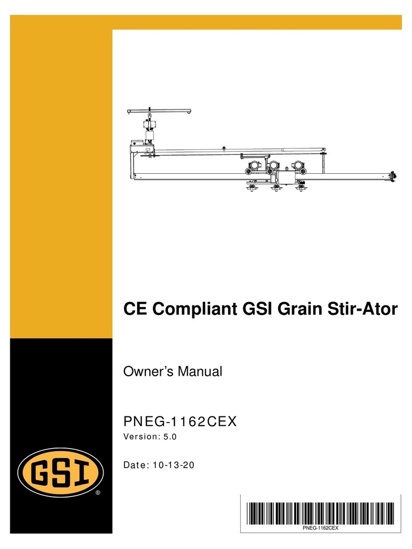
Design III Series Grain
Stir-Ator CSA
Owner’s Manual
PNEG-1156ETL
Date: 06-22-12

2PNEG-1156ETLDesign III Series Grain Stir-Ator CSA
Patent Notice
The Kalke-Murphy Grain Stir-Ator is manufactured under exclusive license for United States Patent
Numbers 3580549 and 4374621. Infringing manufacturers, sellers and users are subject to prosecution
in the Federal Courts.
STIR-ATOR is a registered trade-mark of David Manufacturing Company.
Installation Data
Date of Installation: ______________________
Serial Number: _________________________
Bin Size: ______________________________
Auger Length: __________________________
Dealer Name: ___________________________

Table of Contents
PNEG-1156ETL Design III Series Grain Stir-Ator CSA 3
Contents
Chapter 1 Safety .....................................................................................................................................................5
Safety Guidelines .................................................................................................................................. 5
Safety Instructions ................................................................................................................................. 6
Operator Qualifications ....................................................................................................................... 12
Chapter 2 Safety Decals ......................................................................................................................................13
Chapter 3 Specifications and Dimensions ........................................................................................................15
Design III Stir-Ator Overall Dimensions ............................................................................................... 15
Design III Stir-Ator Standard Equipment Shipping Weights ................................................................ 17
Chapter 4 Assembly and Installation .................................................................................................................19
Final Inspection Check List ................................................................................................................. 19
Installation of Design III Stir-Ator ......................................................................................................... 19
Track Installation ................................................................................................................................. 20
Suspension Chains ............................................................................................................................. 23
Switch Box .......................................................................................................................................... 24
Frame Rails ......................................................................................................................................... 26
Trolley ................................................................................................................................................. 27
Yokes .................................................................................................................................................. 30
Swing Arm ........................................................................................................................................... 33
Junction Box ........................................................................................................................................ 33
Trolley Drive Arm to Cable .................................................................................................................. 35
Center Suspension System ................................................................................................................. 36
Track Gear Motor ................................................................................................................................ 37
Leveler Disks ....................................................................................................................................... 37
Lifting Stir-Ator .................................................................................................................................... 38
Suspension Chain ............................................................................................................................... 41
Installing Stir-Ator Augers ................................................................................................................... 44
Chapter 5 Operation ............................................................................................................................................48
Start-Up Procedure (Full Bin) .............................................................................................................. 48
Track Unit Drive Sprocket ................................................................................................................... 49
Stir-Guard Operation (Optional) .......................................................................................................... 49
Storage ................................................................................................................................................ 50
Drying Guide ....................................................................................................................................... 51
Chapter 6 Parts List .............................................................................................................................................55
Design III Stir-Ator Track Unit ............................................................................................................. 56
Design III Stir-Ator Switch Boxes and Suspension ............................................................................. 58
Design III Stir-Ator Yoke ...................................................................................................................... 60
Design III Stir-Ator Double Auger Trolley ............................................................................................ 64
Design III Stir-Ator Triple Auger Trolley .............................................................................................. 65
DMC 230V - Gear Motor (502A0040) ................................................................................................. 69
DMC 440V - Gear Motor (502A0045) ................................................................................................. 70
Stir-Ator Guard Option - 230V ............................................................................................................. 71
Stir-Ator Guard Option - 440V ............................................................................................................. 72
Chapter 7 Service and Maintenance ..................................................................................................................73
Cable Tension ..................................................................................................................................... 73
Trolley Drive Link ................................................................................................................................ 74
Tilt Switch ............................................................................................................................................ 75
Safety Shut Off Switch ........................................................................................................................ 76
Chapter 8 Troubleshooting .................................................................................................................................77

Table of Contents
4 PNEG-1156ETL Design III Series Grain Stir-Ator CSA
Chapter 9 Wiring Diagrams .................................................................................................................................79
Design III Stir-Ator Wiring Diagram - 1 Phase - 230V - 60 Hz ............................................................ 79
Design III Stir-Ator Wiring Diagram - 3 Phase - 230V - 60 Hz ............................................................ 80
Design III Stir-Ator Wiring Diagram - 3 Phase - 460V - 60 Hz ............................................................ 81
Design III Stir-Ator Wiring Diagram - 3 Phase - 575V - 60 Hz ............................................................ 82
Chapter 10 Warranty ............................................................................................................................................83

PNEG-1156ETL Design III Series Grain Stir-Ator CSA 5
1. Safety
Safety Guidelines
This manual contains information that is important for you, the owner/operator, to know and understand.
This information relates to protecting personal safety and preventing equipment problems. It is the
responsibility of the owner/operator to inform anyone operating or working in the area of this equipment
of these safety guidelines. To help you recognize this information, we use the symbols that are defined
below. Please read the manual and pay attention to these sections. Failure to read this manual and its
safety instructions is a misuse of the equipment and may lead to serious injury or death.
DANGER
WARNING
CAUTION
NOTICE
This is the safety alert symbol. It is used to alert you
to potential personal injury hazards. Obey all safety
messages that follow this symbol to avoid possible
injury or death.
WARNING indicates a hazardous situation which, if not
avoided, could result in death or serious injury.
CAUTION, used with the safety alert symbol, indicates a
hazardous situation which, if not avoided, could result in
minor or moderate injury.
NOTICE is used to address practices not related to
personal injury.
DANGER indicates a hazardous situation which, if not
avoided, will result in death or serious injury.

1. Safety
6PNEG-1156ETLDesign III Series Grain Stir-Ator CSA
Safety Instructions
Our foremost concern is your safety and the safety of others associated with this equipment. We want to
keep you as a customer. This manual is to help you understand safe operating procedures and some
problems that may be encountered by the operator and other personnel.
As owner and/or operator, it is your responsibility to know what requirements, hazards, and precautions
exist, and to inform all personnel associated with the equipment or in the area. Safety precautions may be
required from the personnel. Avoid any alterations tothe equipment. Such alterations may produce a very
dangerous situation where SERIOUS INJURY or DEATH may occur.
This equipment shall be installed in accordance with the current installation codes and applicable
regulations, which should be carefully followed in all cases. Authorities having jurisdiction should be
consulted before installations are made.
Follow Safety Instructions
Carefully read all safety messages in this manual and
safety signs on your machine. Keep signs in good
condition. Replace missing or damaged safety signs. Be
sure new equipment components and repair parts include
the current safety signs. Replacement safety signs are
available from the manufacturer.
Learn how to operate the machine and how to use controls
properly. Do not let anyone operate without instruction.
Keep your machinery in proper working condition.
Unauthorized modifications to the machine may impair
the function and/or safety and affect machine life.
If you do not understand any part of this manual or need
assistance, contact your dealer. Read and Understand Manual

1. Safety
PNEG-1156ETL Design III Series Grain Stir-Ator CSA 7
Practice Safe Maintenance
Understand service procedures before doing work. Keep area
clean and dry.
Never lubricate, service, or adjust machine while it is in operation.
Keep hands, feet and clothing away from rotating parts.
Keep all parts in good condition and properly installed. Fix
damage immediately. Replace worn or broken parts. Remove any
built-up grease, oil, and debris. Maintain Equipment
and Work Area
Stay Clear of Rotating Parts
CAUTION SHOULD BE EXERCISED if it is necessary
to enter the bin while the equipment is in operation.
Entanglement in rotating augers will cause serious
injury or death.
Keep all shields and covers in place at all times.
Wear close fitting clothing. Stop and lock out power
source before making adjustments, cleaning, or
maintaining equipment. Rotating Auger Hazard
Operate Motor Properly
To avoid serious injury or death, stay away from unit and make sure
everyone is clear of the equipment before starting or operating
the unit.
All electrical connections should be made in accordance with
the National Electric Code. Be sure equipment and bins are
properly grounded.
Do not operate electric motor equipped units until motors are
properly grounded.
Disconnect power on electrical driven units before resetting
motor overloads.
Do not repetitively stop and start the drive in order to free a plugged
condition. Jogging the drive in this manner can damage the
equipment and/or drive components.
Electric Shock Hazard

1. Safety
8PNEG-1156ETLDesign III Series Grain Stir-Ator CSA
Prepare for Emergencies
Be prepared if fire starts.
Keep a first aid kit and fire extinguisher handy.
Keep emergency numbers for doctors, ambulance service,
hospital, and fire department near your telephone. Keep Emergency Equipment
Quickly Accessible
Avoid Falls
Anchor the bottom of any ladder being used in a bin or silo
to prevent it from slipping.
Because the equipment is suspended from chains in the
center, be cautious of positioning ladder against the
equipment. The equipment can move or swing from the
weight of a person climbing on the ladder.
When setting a ladder against the equipment, a vise grip
or other type of tie down should be used in the front and
back of the track drive unit. This keeps the equipment from
rolling or sliding around the bin while service work is
being performed.
During heavy service work, such as removing auger
drive, electric motors, or replacing electrical swivel, tying
the ladder to the main frame or other solid component
is advised.
Never climb out on the main beam or augers from a ladder
or the roof manhole.
If an unusual amount of service work needs to be
performed, consider lowering the unit onto sawhorses.
Always Use Ladders Safely

1. Safety
PNEG-1156ETL Design III Series Grain Stir-Ator CSA 9
Wear Protective Clothing
Wear close-fitting clothing and safety equipment appropriate
to the job.
Remove all jewelry.
Tie long hair up and back.
Wear safety glasses at all times to protect eyes from debris.
Wear gloves to protect your hands from sharp edges on
plastic or steel parts.
Wear steel-toed boots to help protect your feet from falling
debris. Tuck in any loose or dangling shoestrings.
A respirator may be needed to prevent breathing potentially
toxic fumes and dust.
Wear a hard hat to help protect your head.
Wear appropriate fall protection equipment when working at
elevations greater than six feet (6').
Eye Protection
Gloves
Steel-Toed Boots
Respirator
Hard Hat
Fall Protection

1. Safety
10 PNEG-1156ETL Design III Series Grain Stir-Ator CSA
1. Read and understand the Owner’s Manual.
2. Keep all safety shields in place.
3. Disconnect all electrical power prior to inspecting, servicing, lubricating or
adjusting the equipment.
4. Keep hands, feet and clothing away from moving parts while in operation.
NEVER stand or sit on unit while in operation.
5. To avoid serious injury or death, stay clear of the unit and make sure everyone
else is clear of the Stir-Ator before starting or operating the unit.
6. DO NOT operate the Stir-Ator unless shut off chain has been properly installed
and adjusted.
7. Never enter the bin while the Stir-Ator is in operation.
8. Exercise care when starting the Stir-Ator in a full bin of grain. Augers can be
stuck in the grain causing damage to the Stir-Ator or to the bin.
9. Operating the Stir-Ator during bin unloading can be beneficial to the unloading
process as well as prevent auger damage.
10. BURYING THE UNIT WILL DAMAGE THE BIN AND WILL VOID THE WARRANTY.
11. DO NOT OPERATE DESIGN III STIR-ATOR IN AN EMPTY BIN. To test the unit in
an empty bin, make sure no one is inside the bin, then turn power “ON” and
“OFF” immediately from the outside of the bin. DO NOT let the Stir-Ator run in
an empty bin. Damage to Stir-Ator and bin can result.
12. All electrical hook-ups must be in accordance with the National Electrical Code.
Be sure equipment and bins are properly grounded.
13. When not operating the unit for extended periods of time or in some cases while
emptying the bin, it may be bestto position the trolley at the bin wall to eliminate
possible Stir-Ator or bin damage.
CAUTION
Familiarize yourself with the machine before operating. This will help you to
operate the Design III Stir-Ator more efficiently and obtain better quality results.
BE A SAFE OPERATOR

1. Safety
PNEG-1156ETL Design III Series Grain Stir-Ator CSA 11
1. Turn OFF and lock out power source.
2. A safe ladder should be used.
3. When setting a ladder against the Stir-Ator, use a vise grip or other type of tie
down in front and back of the track drive unit.This will prevent the Stir-Ator from
rolling or sliding around the bin while service is performed.
4. Because the Stir-Ator is suspended from chains in the center, exercise caution
whenever placing a ladder against the unit. The Stir-Ator can move or swing from
the weight of a person climbing on the ladder.
5. Climbing out on the main frame from either a ladder or roof manhole should NOT
be attempted. The Stir-Ator can swing, causing a fall.
6. During heavy service work, such as removing auger drive, electric motors or
replacing electrical swivel, secure the ladder to the main frame or other
solid component.
7. Use rubber pads or other anti-slip devices to prevent the ladder from slipping on
the bin or silo floor. Slipping could cause a serious accident.
8. DO NOT climb Stir-Ator down augers to make adjustments or repairs. Slipping
could cause falling, bodily injury or both.
9. If an unusual amount of service work is to be performed on a Stir-Ator, consider
removing the augers and lowering the unit onto sawhorses.
10. Exercise caution when using a ladder to perform work in a partially filled grain
bin. The ladder may sink into the grain and cause a fall.
CAUTION
Read and heed all safety reminders listed below.
To perform service work on a stirring device installed in a bin:
SAFETY FIRST PAYS

1. Safety
12 PNEG-1156ETL Design III Series Grain Stir-Ator CSA
Operator Qualifications
A. The User/Operator must be competent and experienced to operate auger equipment. Anyone who
works with or around augers musthave good common sensein order to be qualified. These persons
must also know and meet all other qualifications, such as:
i. Any person who has not read and/or does not understand all operation and safety procedures
is not qualified to operate any auger systems.
ii. Certain regulations apply to personnel operating power machinery. Personnel under the age of
18 years may not operate power machinery, including augers. It is your responsibility, as owner
and/or supervisor, to know what these regulations are in your area or situation.
iii. Unqualified or incompetent persons are to remain out of the work area.
iv. O.S.H.A. (Occupational Safety and Health Administration) regulations state: “At the time of
initial assignment and at least annually thereafter, the employer shall instruct every employee
in the safe operation and servicing of all equipment with which the employee is, or will be
involved”. (Federal Occupational Safety and Health Standards for Agriculture. Subpart D,
Section 1928.57 (a) (6)).
B. As a requirement of O.S.H.A., it is necessary for the employer to train the employee in the safe
operating and safety procedures for this auger. The sign-off sheet is provided for your convenience
and personal record keeping. All unqualified persons are to stay out of the work area at all times. It
is strongly recommended that another qualified person who knows the shut down procedure is in the
area in the event of an emergency.
Date Employee Name Supervisor Name

PNEG-1156ETL Design III Series Grain Stir-Ator CSA 13
2. Safety Decals
The decals shown below and on Page 14 must be displayed as shown.
Replacements are available upon request. Write to the following address:
GSI Group
1004 E. Illinois St.
Assumption, IL. 62510
Phone: 1-217-226-4421
Please note:
1. The decals shown below are not shown in actual size.
2. Keep decals wiped clean at all times.
3. Decals must be replaced if they are destroyed, missing, painted over or can no longer be read.
DC-1386 - Top of gear
motor track frame.
1067021 - Both sides of bottom motor
mounting rail in trolley and both sides of
optional offset. DC-GBC-A and DC-GBC-1S -
Should be located at any bin entry so it can
seen and easily.
DC-1948 - Both
sides of swivel
box plus junction
box cover.
Rotating flighting will
kill or dismember.
Flowing material will
trap and suffocate.
Crusted material will
collapse and suffocate.
Keep clear of all augers.
DO NOT ENTER this bin!
Failure to heed these
warnings will result in
serious injury or death.
If you must enter the bin:
1. Shut off and lock out all power.
2. Use a safety harness and safety line.
3. Station another person outside the bin.
4. Avoid the center of the bin.
5. Wear proper breathing equipment or respirator.
DC-GBC-1A
Moving parts can
crush and cut. Keep
hands clear of
sprocket and chain.
DC-1386
DC-1948
Lockout power
before servicing.
Will cause serious
injury or death.
HIGH VOLTAGE.
Vérouillez le courant
avant l’entretien.
Causera de sérieuses
blessures ou la mort.
HAUTE TENSION

2. Safety Decals
14 PNEG-1156ETL Design III Series Grain Stir-Ator CSA
Rotating flighting will
kill or dismember.
Flowing material will
trap and suffocate.
Crusted material will
collapse and suffocate.
Keep clear of all augers.
DO NOT ENTER this bin!
Failure to heed these
warnings will result in
serious injury or death.
If you must enter the bin:
1. Shut off and lock out all power.
2. Use a safety harness and safety line.
3. Station another person outside the bin.
4. Avoid the center of the bin.
5. Wear proper breathing equipment or respirator.
DC-GBC-1A
This decal is to be located so it can easily be seen and read at any entry point into the bin or silo.

3. Specifications and Dimensions
16 PNEG-1156ETL Design III Series Grain Stir-Ator CSA
Design III Stir-Ator Overall Dimensions (Continued)
(See Figure 3A on Page 15.)
**18' and 18' 7'' Bin diameter available on DA only.
NOTE: 1. DA frame rails up to 36' are 4'' x 3'' x 1/4''
2. DA frame rails 36' to 48' are 5'' x 3'' x 5/16''
3. TA frame rails are 5'' x 3'' x 5/16''
Bin Diameter Dimension “A” DA Dimension “A” TA Dimension “B”
DA and TA Dimension “C”
DA and TA
**18' 40-1/8" NA 114-1/2" 113"
**18' 7'' 43-5/8" NA 118" 116-1/2"
2
21' 58-1/8" 40-1/8" 132-1/2" 131"
21' 7'' 61-5/8" 43-5/8" 136" 134-1/2"
22' 64-1/8" 46-1/8" 138-1/2" 137"
22' 9'' 68-5/8" 50-5/8" 143" 141-1/2"
24' 76-1/8" 58-1/8" 150-1/2" 149"
2
24' 3'' 77-5/8" 59-5/8" 152" 150-1/2"
24' 8'' 80-1/8" 62-1/8" 154-1/2" 153"
27' 94-1/8" 76-1/8" 168-1/2" 167"
27' 10'' 99-1/8" 81-1/8" 173-1/2" 172"
28' 100-1/8" 82-1/8" 174-1/2" 173"
28' 3'' 101-5/8" 83-5/8" 176" 174-1/2"
30' 112-1/8" 94-1/8" 186-1/2" 185"
31' 118-1/8" 100-1/8" 192-1/2" 191"
33' 130-1/8" 112-1/8" 204-1/2" 203"
36' 148-1/8" 130-1/8" 222-1/2" 221"
36' 3'' 149-5/8" 131-5/8" 224" 222-1/2"
39' 166-1/8" 148-1/8" 240-1/2" 239"
40' 172-1/8" 154-1/8" 246-1/2" 245"
42' 184-1/8" 166-1/8" 258-1/2" 257"
48' 220-1/8" 202-1/8" 294-1/2" 293"

3. Specifications and Dimensions
PNEG-1156ETL Design III Series Grain Stir-Ator CSA 17
Figure 3B
Design III Stir-Ator Standard Equipment Shipping Weights
Stir-Atorweights and auger downpullaretwo(2)factorstoconsiderwhendeterminingtheextrastress that
is placed on the drying bin wall and roof.
For total weight, add Chart 1 below and Chart 2 on Page 18 weights together.
Chart 1
Stir-Ator Shipping Weights
Bin Size Double Auger Triple Auger
18' 770 -
21' 808 1030
24' 844 1070
27' 882 1112
30' 920 1150
33' 960 1200
36' 1014 1265
40' 1052 1306
42' 1088 1345
48' 1200 1500
Design III Stir-Ator

3. Specifications and Dimensions
18 PNEG-1156ETL Design III Series Grain Stir-Ator CSA
Design III Stir-Ator Standard Equipment Shipping
Weights (Continued)
Chart 2
Additional Weight with Optional Equipment
2 HP, 1 Phase Motor 33 Lbs. per Motor
2 HP, 3 Phase Motor 13 Lbs. per Motor
18' Augers 5 Lbs. per Auger
20' Augers 10 Lbs. per Auger
Auger Downpull in Pounds Initial Start-Up - Wet Grain
16' Auger 14' Grain 368 Lbs. per Auger
18' Auger 16' Grain 390 Lbs. per Auger
20' Auger 18' Grain 410 Lbs. per Auger
Auger Downpull in Pounds Normal Start-Up - Wet Grain
16' Auger 14' Grain 207 Lbs. per Auger
18' Auger 16' Grain 241 Lbs. per Auger
20' Auger 18' Grain 300 Lbs. per Auger

PNEG-1156ETL Design III Series Grain Stir-Ator CSA 19
4. Assembly and Installation
Final Inspection Check List
1. READ THE STIR-ATOR OWNER’S MANUAL BEFORE INSTALLATION. MANY SERVICE
PROBLEMS WILL BE AVOIDED IF THE STIR-ATOR IS PROPERLY INSTALLED.
2. Is there at least 10-1/4" clearance from the center of the track to the lowest part of the roof and
roof braces?
3. Are the track splices correctly installed? Consult the diagrams in the owner’s manual.
4. Is the trolley installed correctly with the arm pointing toward the center of the bin?
5. Are the bolt heads holding the yoke end to the frame on the inside on the frame rails and the cotter
key spread on the pivot tube?
6. Is the suspension bar properly hung, LEVEL, with the end loops down? Is the 1/2" x 2" bolt holding
suspension bar tightly secured? Is the lock nut on tee fitted properly?
7. Is the suspension bar positioned so that the bin “S” hook, to which the shut off chain is attached,
is at a right angle to the switch box chain, as shown in Figure 4F on Page 23. THE POWER CORD
MUST HAVE MORE SLACK THAN THE SHUT OFF CHAIN or the power cord could be torn out of
the switch box if the Design III should malfunction and engage the shut off.
8. Is the frame of the Design III Stir-Ator approximately 1" higher at the center of the bin for each
18' of bin diameter?
9. Are augers 3" (for bins up to 30') or 4" (for bins 33' and larger) off the drying floor at bin wall?
(See Figure 4AU on Page 45.)
10. Were the augers deburred with a file? Were the clamp bolts torqued to 140 foot-pounds? Was the
roll pin installed correctly?
11. Did you note the instruction NOT to weld flighting at the top end of the auger?
12. Are you sure that the electrician connected the black and red - 1 phase wire to the disconnect box or
connect the black, red and white - 3 phase terminals in the disconnect box and the green wire to the
ground? (See Wiring Diagrams on Pages 79-82.) BE SURE BIN IS GROUNDED.
13. Are you keeping a record of the serial number for each owner?
14. Did you make sure that the owner received and signed for his OWNER’S MANUAL and was
instructed that reading and understanding themanual are essential for proper and efficient operation
of the Stir-Ator?
15. Did you install the safety decals on the inside and outside of the walk-in door and the manhole cover?
Installation of Design III Stir-Ator
NOTE: Prior to assembly and installation, consult the bin erection manual or manufacturer for any special
unit hanging or support locations.
1. Before assembling the bin, place the Design III Stir-Ator (without the augers) in the center of the bin
floor. The top ring of the bin is then assembled in the usual way.

4. Assembly and Installation
20 PNEG-1156ETL Design III Series Grain Stir-Ator CSA
Track Installation
NOTE: The wall track has two (2) different hole spacings: 18-15/16" on the single and double auger units
and 12-5/8" on the triple auger units. (See Figure 4A.)
Figure 4A
1. The track is installed 10-1/4" distance from the eave of the bin to thecenter line of the track. Bins with
steeply pitched or domed roofs may allow the 10-1/4" distance to be reduced; roofs with low or flat
profiles may require more clearance. Reinforcements to the roof or roof ladder which might interfere
with the movement of the Stir-Ator should be trimmed. (See Figure 4B.) If this cannot be done, the
10-1/4" distance from the eave to the track bolt center line must be increased proportionately.
Figure 4B
Design III Stir-Ator
This manual suits for next models
2
Table of contents
Other GSi Industrial Equipment manuals

GSi
GSi 1200 User manual

GSi
GSi 2000 Series User manual

GSi
GSi PNEG-1393 User manual

GSi
GSi EVO-50 Instructions for use

GSi
GSi Flex-Flo 220 Guide

GSi
GSi RSG1212GM-X21 User manual

GSi
GSi TopDry Autoflow 36 FT DIAMETER Instructions for use

GSi
GSi Agri-Alert 128 Touch Manual

GSi
GSi JS500 User manual

GSi
GSi PNEG-1583 User manual

GSi
GSi PNEG-1162CEX User manual

GSi
GSi PNEG-2286 User manual

GSi
GSi PNEG-1859 Instructions for use

GSi
GSi 2021 User manual

GSi
GSi 40 Series Instructions for use

GSi
GSi PNEG-1829 User manual

GSi
GSi 40 Series Instructions for use

GSi
GSi Cumberland FLX-4629 User manual

GSi
GSi TopDry User manual

GSi
GSi VersaLoop 8 User manual