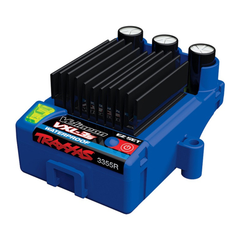
Traxxas Velineon 3350 User manual

Modellbau Lindinger GmbH Alte-Post-Str. 14 A-4591 Molln e-Mail: office@lindinger.at www.lindinger.at
extreme brushless powerextreme brushless power
extreme brushless power systemextreme brushless power system
owners manual
PART #3350

Modellbau Lindinger GmbH Alte-Post-Str. 14 A-4591 Molln e-Mail: office@lindinger.at www.lindinger.at
2 •VELINEON POWER SYSTEM
Traxxas
1100 Klein Road
Plano, Texas 75074
Phone: 972-265-8000
Toll-free 1-888-TRAXXAS
Traxxas U.K.
P.O. Box 1128
Winterbourne, Bristol
BS36-2SH
England
Phone: 44-117-956-1002
Internet
www.Traxxas.com
E-mail: [email protected]
Entire contents ©2007 Traxxas.
Traxxas, Ready-To-Race, Ready-
To-Win, Rustler, Bandit, Stampede
Velineon and ProGraphix are
trademarks or registered trademarks
of Traxxas. Other brand names and
marks are the property of their
respective holders and are used only
for purposes of identication. No part
of this manual may be reproduced
or distributed in print or electronic
media without the express written
permission of Traxxas. Specications
are subject to change without notice.
3BEFORE YOU PROCEED
4SAFETY PRECAUTIONS
6INTRODUCTION
7ANATOMY OF THE VXL-3S
AND VELINEON 3500
8TERMINOLOGY
10 VELINEON SYSTEM
SPECIFICATIONS
11 VELINEON SYSTEM
INSTALLATION
16 VXL-3S SETUP AND
OPERATION
22 GEARING OPTIONS
24 MOTOR OPTIONS
26 TROUBLESHOOTING

Modellbau Lindinger GmbH Alte-Post-Str. 14 A-4591 Molln e-Mail: office@lindinger.at www.lindinger.at
VELINEON POWER SYSTEM •3
Before You Proceed
Carefully read and follow all instructions in this and any accompanying materials to prevent serious damage
to your system. Failure to follow these instructions will be considered abuse and/or neglect.
Before using your system, look over this entire manual and examine the system carefully. If for some reason
you decide it is not what you wanted, then do not continue any further. Your hobby dealer absolutely
cannot accept a system for return or exchange after it has been used.
Support
If you have any questions about your system or its operation, call the Traxxas Technical Support line toll-free
at: 1-888-TRAXXAS (1-888-872-9927).*
Technical support is available Monday through Friday from 8:30am to 9:00pm central time. Technical assistance
is also available at www.Traxxas.com/support. You may also e-mail customer support with your question at
support@Traxxas.com. Join thousands of registered members in our online community at Traxxas.com.
Traxxas offers a full-service, on-site repair facility to handle any of your Traxxas service needs. Maintenance and
replacement parts may be purchased directly from Traxxas by phone or online at www.BuyTraxxas.com. You can
save time, along with shipping and handling costs, by purchasing replacement parts from your local dealer.
Do not hesitate to contact us with any of your product support needs. We want you to be thoroughly satised
with your new system!

Modellbau Lindinger GmbH Alte-Post-Str. 14 A-4591 Molln e-Mail: office@lindinger.at www.lindinger.at
4 •VELINEON POWER SYSTEM
Safety Precautions
VXL-3s Electronic Speed Control
•
Water and Electronics Do Not Mix: Do not operate in
or around water. Never allow water, moisture, or other
foreign materials to get inside the speed control.
• Disconnect the Batteries: Always disconnect the battery
pack from the speed control when not in use.
• Transmitter on First: Switch on your transmitter first
before switching on the speed control to prevent
runaways and erratic performance.
• Don’t Get Burned: The heat sink can get extremely
hot, so be careful not to touch it until it is cool. Supply
adequate airflow for cooling.
• Use Stock Connectors: If you decide to change the
battery or motor connectors, only change one battery
or motor connector at a time. This will prevent damage
from accidentally mis-wiring the speed control. Please
note that modified speed controls can be subject to a
rewiring fee when returned for service. Removing the
battery connector on the speed control or using the
same-gender connectors on the speed control will void
the product’s warranty.
• Insulate the Wires: Always insulate exposed or damaged
wiring with heat shrink tubing to prevent short circuits.
Batteries and Battery Charging
The Velineon Power System
uses rechargeable batteries
that must be handled with care for safety and long battery
life. Make sure to read and follow all instructions and
precautions that were provided with your battery packs
and your charger. It is your responsibility to charge and
care for your battery backs properly. In addition to your
battery and charger instructions, here are some more tips
to keep in mind.
• Never leave batteries to charge unattended.
• Remove the batteries from the model while charging.
• Allow the battery packs to cool off between runs
(before charging).
• Always unplug the battery from the electronic speed
control when the model is not in use and when it is
being stored or transported.
• Do not use battery packs that have been damaged in
any way.
• Do not use battery packs that have damaged wiring,
exposed wiring, or a damaged connector.
• Children should have responsible adult supervision when
charging and handling batteries.

Modellbau Lindinger GmbH Alte-Post-Str. 14 A-4591 Molln e-Mail: office@lindinger.at www.lindinger.at
VELINEON POWER SYSTEM •5
LiPo Batteries
Lithium Polymer (LiPo) batteries are becoming popular for
use in R/C models due to their compact size, high energy
density, and high-current output. However, these types
of batteries require special care and handling procedures
for long life and safe operation. Warning: LiPo batteries
are intended only for advanced users that are educated
on the risks associated with LiPo battery use. Traxxas does
not recommend that anyone under the age of 16 use or
handle LiPo battery packs without the supervision of a
knowledgeable and responsible adult.
The VXL-3s electronic speed control is able to use LiPo
batteries with nominal voltage not to exceed 11.1 volts
(3S packs) volts. LiPo batteries have a minimum safe
discharge voltage threshold that should not be exceeded.
The Velineon VXL-3s electronic speed control is equipped
with built-in Low-Voltage Detection that alerts the driver
when LiPo batteries have reached their minimum voltage
(discharge) threshold. It is the driver’s responsibility
to stop immediately to prevent the battery pack from
being discharged below its safe minimum threshold.
Low-Voltage Detection on the speed control is just one
part of a comprehensive plan for safe LiPo battery use.
It is critical for you, the user, to follow all other
instructions supplied by the battery manufacturer and
the charger manufacturer for proper charging, use, and
storage of LiPo batteries. Make sure you understand
how to use your LiPo batteries. Be aware that Traxxas
shall not be liable for any special, indirect, incidental, or
consequential damages arising out of the installation
and/or use of LiPo batteries in Traxxas products.
If you have questions about LiPo battery usage, please
consult with your local hobby dealer or contact the battery
manufacturer.
Safety Precautions

Modellbau Lindinger GmbH Alte-Post-Str. 14 A-4591 Molln e-Mail: office@lindinger.at www.lindinger.at
6 •VELINEON POWER SYSTEM
Introduction
Thank you for purchasing the new Velineon™ Brushless Power System. The Velineon Power System lets you
experience the best that brushless motor technology has to offer. Incredible speed, efcient operation, long run
times, and low-maintenance operation are just some of the benets. We are condent you will be rewarded with
high-speed performance in a durable, long-lasting product.
This manual contains the instructions you will need to operate, and maintain your system. We want you to
feel condent that you own one of the best-performing products in the market and that it is backed by a team
of professionals who aim to provide the highest level of factory support possible. Traxxas products are about
experiencing total performance and satisfaction, not just with your system, but also with the company that stands
behind it.
We know you’re excited about getting your new system installed, but it’s very important that you take some time
to read through the Owners Manual. This manual contains all the necessary set-up and operating procedures that
will allow you to unlock the performance potential that Traxxas engineers designed into your system. Also be sure
to read and follow the precautions and warnings in this manual and on any labels or tags attached to your system.
They are there to educate you on how to operate your system safely and also get maximum life and performance
from your system.
Even if you are an experienced R/C enthusiast, it’s important to read and follow the procedures in this manual.
Thank you again for going with Traxxas. We work hard every day to assure you receive the highest level of
customer satisfaction possible. We truly want you to enjoy your new system!

Modellbau Lindinger GmbH Alte-Post-Str. 14 A-4591 Molln e-Mail: office@lindinger.at www.lindinger.at
VELINEON POWER SYSTEM •7
Anatomy of the VXL-3s and Velineon 3500
to Motor
LED
EZ-Set Button
(On/Off Button)
Heat Sink
Traxxas High-Current
Connector (Male)
to Battery
(see page 15)
Auxiliary Port
(for optional use)
Receiver cable
(RX wire)
Cooling Fan
Connector
(for optional use)
to ESC
Bullet
Connector
Motor Cap
Rotor
(Magnet)
Ball Bearings
Motor Shaft
Windings
(Coils)

Modellbau Lindinger GmbH Alte-Post-Str. 14 A-4591 Molln e-Mail: office@lindinger.at www.lindinger.at
8 •VELINEON POWER SYSTEM
Please take a moment to familiarize yourself with these
terms. They will be used throughout this manual.
Brushless Motor - A D/C brushless motor replaces the
brushed motor’s traditional commutator and brush
arrangement with intelligent electronics that energize
the electromagnetic windings in sequence to provide
rotation. Opposite of a brushed motor, the brushless
motor has its windings (coils) on the perimeter of
the motor can and the magnets are mounted to the
spinning rotor shaft.
Cogging - Cogging is a condition sometimes associated
with brushless motors. Typically it is a slight stutter
noticed when accelerating from a stop. It happens for
a very short period as the signals from the electronic
speed control and the motor synch with each other.
The VXL-3s electronic speed control is optimized to
virtually eliminate cogging.
Current - Current is a measure of power ow through
the electronics, usually measured in amps. If you look
at wire like a garden hose, current is a measure of how
much water is owing through the hose.
ESC (Electronic Speed Control) - An electronic speed
control is the electronic motor control inside the
model. The VXL-3s electronic speed control uses
advanced circuitry to provide precise, digital
proportional throttle control. Electronic speed
controls use power more efciently than mechanical
speed controls so that the batteries run longer.
An electronic speed control also has circuitry that
prevents loss of steering and throttle control as the
batteries lose their charge.
kV Rating - Brushless motors are often rated by their kV
number. The kV rating equals no-load motor rpm with
1 volt applied. The kV increases as the number of wire
turns in the motor decreases. As the kV increases, the
current draw through the electronics also increases.
The Velineon 3500 motor is a 10-turn, 3500 kV
motor optimized for the best speed and efciency in
lightweight 1/10 scale models.
LiPo - Abbreviation for Lithium Polymer. Rechargeable
LiPo battery packs are known for their special
chemistry that allows extremely high energy density
and current handling in a compact size. These are
high performance batteries that require special care
and handling. For advanced users only.
mAh – Abbreviation for milliamp hour. A measure of the
capacity of the battery pack. The higher the number,
the longer the battery will last between recharges.
Terminology
Modellbau Lindinger GmbH Alte-Post-Str. 14 A-4591 Molln e-Mail: office@lindinger.at www.lindinger.at
VELINEON POWER SYSTEM •9
NiMH - Abbreviation for nickel-metal hydride.
Rechargeable NiMH batteries offer high current
handling, and much greater resistance to the
“memory” effect. NiMH batteries generally allow
higher capacity than NiCad batteries. They can last
up to 500 charge cycles. A peak charger designed for
NiMH batteries is required for optimal performance.
Resistance - In an electrical sense, resistance is a
measure of how an object resists or obstructs the ow
of current through it. When ow is constricted, energy
is converted to heat and is lost. The Velineon power
system is optimized to reduce electrical resistance
and the resulting power-robbing heat.
Rotor - The rotor is the main shaft of the brushless
motor. In a brushless motor, the magnets are
mounted to the rotor, and the electromagnetic
windings are built into the motor housing.
Sensored - Sensored refers to a type of brushless
motor that uses an internal sensor in the motor to
communicate rotor position information back to
the electronic speed control. The VXL-3s electronic
speed control is able to use sensored motors when
applications benet from them (such as some
sanctioned racing classes).
Sensorless - Sensorless refers to a brushless motor that
uses advanced instructions from an electronic speed
control to provide smooth operation. Additional
motor sensors and wiring are not required. The VXL-
3s electronic speed control is optimized for smooth
sensorless control.
Solder Tabs - Accessible, external contacts on the motor
that allows for easy wire replacement. The Velineon
3500 is equipped with solder tabs.
Thermal Shutdown Protection - Temperature sensing
electronics used in the VXL-3s electronic speed
control detect overloading and overheating of
the transistor circuitry. If excessive temperature
is detected, the unit automatically shuts down to
prevent damage to the electronics.
Voltage - Voltage is a measure of the electrical potential
difference between two points, such as between
the positive battery terminal and ground. Using
the analogy of the garden hose, while current is
the quantity of water ow in the hose, voltage
corresponds to the pressure that is forcing the water
through the hose.

Modellbau Lindinger GmbH Alte-Post-Str. 14 A-4591 Molln e-Mail: office@lindinger.at www.lindinger.at
10 •VELINEON POWER SYSTEM
Velineon System Specifications
VXL-3s Specifications:
Input voltage: 4.8 - 11.1V (4 - 9 cells NiMH or 2S - 3S LiPo)
Supported motors: Brushed / Brushless / Sensorless brushless
Motor limit: None
Continuous current: 200A
Peak current: 320A
BEC voltage: 6.0V DC
Transistor type: MOSFET
On-resistance: 0.00075 Ω Max (0.006/8 FETs)
PWM frequency: 12,000Hz
Battery connector: Traxxas High-Current Connector
Motor connectors: TRX 3.5mm bullet connectors
Motor/battery wiring: 12-gauge Maxx
®
Cable
Thermal protection: 2-stage thermal shutdown
Case size (l/w/h): 55mm (2.19")/ 39mm (1.54")/ 33mm (1.3")
Weight: 90g (3.17oz)
Velineon 3500 Specifications:
Type: Sensorless brushless
RPM/volt: 3500 (10-turn)
Magnet type: Ultra High-Temperature
Sintered Neodymium
Connection type: TRX 3.5mm bullet connectors
Wire size: 12-gauge Maxx
®
Cable w/ solder tabs
Current Ratings: 65A constant; 100A peak/burst
Max RPM: 50,000
Diameter: 36mm (1.42”) (540 size)
Length: 55mm (2.165”)
Weight: 262g (9.24oz)
VXL-3s Profile Selection:
Prole #1 (Sport Mode): 100% Forward, 100% Brakes, 100% Reverse
Prole #2 (Race Mode): 100% Forward, 100% Brakes, No Reverse
Prole #3 (Training Mode): 50% Forward, 100% Brakes, 50% Reverse

Modellbau Lindinger GmbH Alte-Post-Str. 14 A-4591 Molln e-Mail: office@lindinger.at www.lindinger.at
VELINEON POWER SYSTEM •11
The following instructions cover installation of the Velineon System in an XL-5 equipped Rustler (Model 3705), Bandit
(Model 2405) or Stampede (Model 3605). The Velineon System is capable of extreme power, and the drivetrain upgrades
below are recommended to increase the performance and durability of the XL-5 equipped model being upgraded to
Velineon Power.
Minimum recommended XL-5 equipped vehicle component upgrades:
2381X Main diff with steel ring gear/ side cover plate/ screws (Bandit, Stampede, Rustler)
2753X Stub axles, rear (2)
4628R Differential output yokes, black (2)/ 3x5mm countersunk screws (2)/ screw pin (2)
3696 Idler gear, steel (30-tooth)
Additional suggested XL-5 equipped vehicle component upgrades:
3647 Nuts, 4mm flanged nylon locking (steel, serrated) (8)
3752 Stub axle carriers (2) (requires 5x11x4mm bearings)
3736 Steering blocks, left & right (2) (requires 5x11x4mm bearings)
5116 Ball bearings, blue rubber sealed (5x11x4mm) (2)
Removing the XL-5 system
1. Remove the right rear wheel (passenger rear).
2. Remove the two 3x6mm screws from the gear cover and remove
the gear cover (A).
3. Loosen the motor pinion gear set screw (B, yellow arrow) and slide
the gear off the motor shaft. Disconnect the motor wires and loosen
the two 3x8mm washerhead screws until the motor is free of the
gearbox (B). Remove the motor.
Velineon System Installation
AB
Screw Options Note: Other than the 3x15mm
cap screws for mounting the servo to the
servo plate, all the original hardware on your
model can be reused. 3x8mm flathead hex
screws are included if you wish to upgrade
your motor screws to hex hardware.

Modellbau Lindinger GmbH Alte-Post-Str. 14 A-4591 Molln e-Mail: office@lindinger.at www.lindinger.at
12 •VELINEON POWER SYSTEM
Velineon System Installation
4. Remove the Speed control’s XL-5 plug from Channel 2 of your
receiver (see wiring diagram, next page).
5. Remove the two 3x12mm washerhead screws that hold the XL-5 to
its mount (C). Remove the XL-5.
6. Remove the four 3x8mm washerhead screws from the ESC mount.
Remove the mount and discard (D).
Installation of the Velineon System:
1. Install the included ESC mounting plate using the 3x8mm screws (E).
2. Mount the VXL-3s to the new mounting plate using the supplied
3x15mm cap screws (F).
3. Mount the Velineon Motor to the gearbox using the 3x8mm
washerhead screws (or the included flathead hex screws) and tighten
finger tight (G, white arrows).
4. Mount the motor pinion to the motor shaft, make sure to tighten set
screw against the flat portion of the shaft (G).
5. Set the gear mesh by running a narrow strip of notebook paper into
the gear mesh. Loosen the motor screws and slide the motor and
pinion gear into the spur gear. Retighten the motor screws and then
remove the strip of paper (H).
6. Replace the gear dust cover and the wheel.
7. Connect the Velineon motor wires and the VXL-3s receiver wire
according to the wiring diagram (see next page).
8. See page 16 for VXL-3s setup and operation.
CD
EF
GH
Motor
Screws
Strip of
Paper

Modellbau Lindinger GmbH Alte-Post-Str. 14 A-4591 Molln e-Mail: office@lindinger.at www.lindinger.at
VELINEON POWER SYSTEM •13
Antenna
Channel 1
Channel 2
Not Used
Receiver
Velineon 3500
Brushless Motor
Channel 2
Electronic Speed
Control
Channel 1
Steering Servo
Traxxas High-Current
Connector (Male)
to Battery
(see page 15)
Cooling Fan Connector
(for optional use, see page 14)
Motor Cap
Wiring Diagrams Velineon System Installation

Modellbau Lindinger GmbH Alte-Post-Str. 14 A-4591 Molln e-Mail: office@lindinger.at www.lindinger.at
14 •VELINEON POWER SYSTEM
Velineon System Installation
Some users may wish to experience the power of the
Velineon Brushless Power System in other applications.
Here are some tips:
• The VXL-3s does not use a conventional on/off switch.
Pressing the EZ-Set button on the speed control turns it
on and off. It is not necessary to install an on/off switch
into the wiring harness.
• Mount the speed control so that none of the power
components (wiring, motor, ESC) contacts any part of the
radio system, particularly the antenna wire. The receiver
should be mounted so the antenna wire can be extended
as far away from the speed control as possible. The
antenna wire should be extended vertically in the mast
and not wrapped on the chassis under the body. Excess
antenna wire should not be coiled on the chassis. Servo
cables and the antenna wire should not cross or come
in contact with any of the motor or battery wires. These
steps will help reduce the possibility of radio interference.
• If you are planning to operate the system at the higher
limits of its capabilities, cut ventilation holes into the
body for the heat sinks. Monitoring temperatures will
extend the lives of the batteries and motors and proper
ventilation and cooling will prevent premature thermal
shutdown. There are many options available that will help
you monitor temperatures and cool your components:
Temperature gauge - An on-board
temperature gauge such as the
Traxxas part #4091 can aid you in
monitoring your motor temperature.
Generally, try to keep your motor
below 200° F.
Heat sink cooling fan - The VXL-3s
is equipped with an additional
connector to supply power to an
optional heat sink cooling fan. An
optional heat sink cooling fan can assist
in cooling the VXL-3s in high current motor applications.
• Mount the speed control where it will be protected from
crash damage. Also protect the speed control from dirt
and debris kicked up by the tires.
• Mount the speed control where you will have easy access
to the plugs and the on/off (EZ-Set) button without having
to remove the body.
Installing the Velineon System in Other Models

Modellbau Lindinger GmbH Alte-Post-Str. 14 A-4591 Molln e-Mail: office@lindinger.at www.lindinger.at
VELINEON POWER SYSTEM •15
Velineon System Installation
• Graphite or metal chassis have been known to transmit
radio noise generated by the motor. If the receiver
is to be mounted on the chassis, position it so the
crystal and antenna are as far away from the chassis as
possible. This may require you to mount the receiver on
its side. This will reduce the chance of picking up radio
interference from the motor.
• For installations without using the servo
mounting plate, the VXL-3s can be
installed with double-sided servo tape.
The screw bosses may need to be cut from
the case with a pair of side cutters to allow
the VXL-3s to fit in non-Traxxas models. When mounting
the speed control with double-sided servo tape, clean both
application surfaces thoroughly with alcohol. The surfaces
must be perfectly clean for maximum adhesion.
Traxxas High Current Connector
Your system is equipped with the
Traxxas High-Current Connector.
Standard connectors restrict current
ow and are not capable of delivering
the power needed to maximize the
output of the Velineon Brushless Power system.
The Traxxas connector’s gold-plated terminals with a
large contact surfaces ensure positive current ow with
the least amount of resistance. Secure, long-lasting, and
easy to grip, the Traxxas connector is engineered to
extract all the power your battery has to give.
To run this system, your batteries must be equipped
with Traxxas High-Current Connectors. Batteries can
either be purchased new with Traxxas connectors
installed or Traxxas connectors can be purchased to
install on battery packs you already own. For best
performance, your system requires NiMH battery packs
that have cells rated for high discharge and use high-
quality, low-resistance assembly techniques. Cheaply
made battery packs do not retain their performance
characteristics after repeated uses in high-powered
electric applications. They will lose their punch and
run time and may require frequent replacement. In
addition, poor-quality, high-resistance cell connectors
could fail, requiring disassembly and repair. The main
goal is to reduce all sources of high resistance in the
pack. This includes the connector, the wire, and the
bars attaching the cells together. High pack resistance
will create additional heat and rob you of the full power
the cells are capable of producing.

Modellbau Lindinger GmbH Alte-Post-Str. 14 A-4591 Molln e-Mail: office@lindinger.at www.lindinger.at
16 •VELINEON POWER SYSTEM
Traxxas TQ Radio Systems
Before attempting to program your VXL-3s, it is important
to make sure your TQ transmitter is properly adjusted (set
back to the factory defaults). Otherwise, you may not get
the best performance from your speed control.
The transmitter should be adjusted as follows:
1. Set the throttle neutral switch to the 50/50 setting.
This adjusts the transmitter’s throttle trigger throw
to 50% for throttle and 50% for braking and reverse.
Experienced users may wish to use the 70/30 setting if
more broad proportional control is desired in forward
than with braking and reverse. This might be desirable
in a racing environment where reverse is disabled.
2. Set the throttle trim control to the middle “0” setting.
3. Set the Channel 2 servo reversing switch to the left
position. Do not change the position of any of the servo
reversing switches after programming the VXL-3s.
4. You are now ready to program your speed control.
Aftermarket (Non-Traxxas) Transmitters
The following instructions are provided as a general
reference only for those who are using non-Traxxas
transmitters. Consult your transmitter’s instructions for
information on how to change the settings.
1. Set the High ATV (adjustable travel volume) or EPA
(end point adjustment) to the maximum setting. This
is the amount of servo throw at full throttle.
2. Set the Low ATV, EPA or ATL (low side only trim
adjustment) to the maximum setting. This is the
amount of servo throw at full brakes or reverse.
3. Set the throttle trim to the middle (neutral setting).
4. Set the throttle channel reversing switch to either
position. Do not change the switch position after
programming.
5. Set the trigger throw adjustment to 50% throttle and
50% brake (either mechanical or electronic).
6. Set the exponential setting (if equipped) to the zero or
fully linear setting.
Aftermarket Receivers
The VXL-3s is compatible with most
aftermarket receivers. By removing
the tab on the edge of the power
connector, the VXL-3s can be plugged
directly into some models of Futaba
®
,
Airtronics
®
, Hitec
®
, and JR
®
receivers.
Please refer to the manufacturer’s wiring diagrams that
came with your receiver. On the VXL-3s, the red wire is
VXL-3s Setup and Operation

Modellbau Lindinger GmbH Alte-Post-Str. 14 A-4591 Molln e-Mail: office@lindinger.at www.lindinger.at
VELINEON POWER SYSTEM •17
positive, the black wire is negative, and the white wire
is the control wire. Warning: On some older Airtronics
®
radio systems, the positive and negative terminals
are opposite of the VXL-3s and an adapter is required.
Crossing the red (+) and black (-) wires could damage the
receiver and the VXL-3s. Study the manufacturer’s wiring
diagrams closely, or consult your hobby dealer.
Low-Voltage Detection Setting
The Velineon VXL-3s electronic speed control is equipped
with built-in Low-Voltage Detection. The Low Voltage
Detection circuitry constantly monitors the battery
voltage. When the battery voltage begins to reach the
minimum recommended discharge voltage threshold for
LiPo battery packs, the VXL-3s will limit the power output
to 50% throttle. When the battery voltage attempts to
fall below the minimum threshold, the VXL-3s will shut
down all motor output. The LED on the speed control will
slowly blink red, indicating a low voltage shutdown. The
VXL-3s will stay in this mode until a fully charged battery is
connected. The electronic speed control is factory set with
Low-Voltage Detection turned on. Low-Voltage Detection
can be turned off for a slight increase in run-time when
using NiMH batteries. Traxxas recommends leaving Low
Voltage Detection on at all times. When Low Voltage
Detection interrupts driving, NiMH batteries will already
be at the end of their useful charge and voltage will be
decreasing rapidly. Never use LiPo batteries while Low-
Voltage Detection is turned off.
Verify that Low-Voltage Detection is turned on:
1. Turn on the transmitter (with the throttle at neutral).
2. Connect a fully charged battery pack to the VXL-3s.
3.
Press and release the EZ-Set button to turn the VXL-3s
on. If the LED is solid green, then
Low-Voltage Detection is ON). If the LED is solid red, then
the Low-Voltage Detection is OFF (not safe to use LiPo
batteries).
To turn Low-Voltage Detection off (NiMH setting):
1.
Make sure the LED on the VXL-3s is
on and green.
2.
Press and hold the EZ-Set button
for ten seconds. The LED will
turn off and then light red. Also,
a “falling” musical tone will be
emitted from the motor.
3. Low-Voltage Detection is now OFF.
VXL-3s Setup and Operation
1
2

Modellbau Lindinger GmbH Alte-Post-Str. 14 A-4591 Molln e-Mail: office@lindinger.at www.lindinger.at
18 •VELINEON POWER SYSTEM
To turn Low-Voltage Detection on (LiPo setting):
1. Make sure the LED on the VXL-3s is
on and red.
2. Press and hold the EZ-Set button
for ten seconds. The LED will turn
off and then light green. Also,
a “rising” musical tone will be
emitted from the motor.
3. Low-Voltage Detection is now ON.
VXL-3s Setup Programming
(Calibrating your ESC and transmitter)
Read through all of the programming steps before you
begin. If you get lost during programming or receive
unexpected results, simply unplug the battery, wait a few
seconds, plug the battery back in, and start over.
1. Connect a fully charged battery
pack to the VXL-3s.
2. Turn on the transmitter (with the
throttle at neutral).
3. Press and hold the EZ-Set
button (A). The LED will rst
turn green and then red.
Release the EZ-Set button.
4. When the LED blinks RED
ONCE. Pull the throttle trigger
to the full throttle position and
hold it there (B).
5. When the LED blinks RED
TWICE. Push the throttle trigger to
the full reverse and hold it there (C).
6. When the LED blinks GREEN ONCE,
programming is complete. The LED will then shine green
or red (depending on low-voltage detection setting)
indicating the VXL-3s is on and at neutral (D).
VXL-3s Operation
To operate the speed control and test programming,
place the vehicle on a stable block or stand so that all
of the driven wheels are off the ground. Disconnect
motor wires “A” and “C”, this will assure the motor
does not drive the wheels during testing. Do not test
programming without disconnecting the motor wires.
Note that in the following steps 1-7, Low Voltage Detection
is turn ON (factory default) and the LED shines green. If Low
Voltage Detection is OFF, the LED will shine red instead of
green in the following steps 1-7.
Green then Red
A
Once Red
B
Twice Red
C
Once Green
D
VXL-3s Setup and Operation
1
2

Modellbau Lindinger GmbH Alte-Post-Str. 14 A-4591 Molln e-Mail: office@lindinger.at www.lindinger.at
VELINEON POWER SYSTEM •19
VXL-3s Setup and Operation
1. With the transmitter on, press and release the EZ-Set
button. The LED will shine green. This turns the VXL-3s on.
2. Apply forward throttle. The LED will turn off until full
throttle power is reached. At full throttle, the LED will
illuminate green.
3. Move the trigger forward to apply the brakes. Note that
braking control is fully proportional. The LED will turn off
until full braking power is reached.
At full brakes, the LED will illuminate green.
4. Return the throttle trigger to neutral. The LED will
shine green.
5. Move the throttle trigger forward again to engage reverse
(Prole #1). The LED will turn off. Once full reverse power is
reached, the LED will illuminate green.
6. Return the throttle trigger to neutral. (Note: There is
programmed delay when changing from reverse to
forward. This prevents damage to the transmission on
high-traction surfaces.)
7. To turn the VXL-3s off, press the EZ-Set button until the
LED turns off (.5 seconds).
VXL-3s Profile Selection
The speed control is factory set to Profile #1 (100%
forward, brakes, and reverse). To disable reverse (Profile
#2) or to allow 50% forward and 50% reverse (Profile
#3), follow the steps below. The speed control should be
connected to the receiver and battery, and the transmitter
should be adjusted as described previously. The profiles
are selected by entering the programming mode.
Prole Description
Prole #1 (Sport Mode):
100% Forward, 100% Brakes, 100% Reverse
Prole #2 (Race Mode):
100% Forward, 100% Brakes, No Reverse
Prole #3 (Training Mode*):
50% Forward, 100% Brakes, 50% Reverse
Selecting Sport Mode
(Prole #1: 100% Forward, 100% Brakes, 100% Reverse)
1. Connect a fully charged battery pack to the VXL-3s and
turn on your transmitter.
2. With the VXL-3s off, press and hold the
EZ-Set button until the LED turns solid
green, then solid red and then begins
blinking red (indicating the Prole #).
A
Green to Red to Off
*patent pending

Modellbau Lindinger GmbH Alte-Post-Str. 14 A-4591 Molln e-Mail: office@lindinger.at www.lindinger.at
20 •VELINEON POWER SYSTEM
3. When the LED blinks
red once, release the
EZ-Set button.
4. The LED will blink and
then turn solid green
(Low-Voltage Detection ON) or red
(Low-Voltage Detection OFF). The
model is ready to drive.
Selecting Race Mode
(Prole #2: 100% Forward, 100% Brakes, No Reverse)
1. Connect a fully charged
battery pack to the VXL-3s
and turn on your transmitter.
2. With the VXL-3s off, press
and hold the EZ-Set button
until the LED turns solid
green, then solid red and
then begins blinking red
(indicating the Prole #).
3. When the LED blinks red twice, release the EZ-Set button.
4. The LED will blink and then turn solid green (Low-Voltage
Detection ON) or red (Low-Voltage Detection OFF). The
model is ready to drive.
Selecting Training Mode
(Prole #3: 50% Forward, 100% Brakes, 50% Reverse)
1. Connect a fully charged
battery pack to the VXL-3s
and turn on your transmitter.
2. With the VXL-3s off, press
and hold the EZ-Set button
until the LED turns solid
green, then solid red and
then begins blinking red
(indicating the Prole #).
3. When the LED blinks red three times, release the
EZ-Set button.
4. The LED will blink and then turn solid green (Low-Voltage
Detection ON) or red (Low-Voltage Detection OFF). The
model is ready to drive.
Note: If you missed the mode you wanted, keep the EZ-
Set button pressed down and the blink cycle will repeat
until the button is released and a Mode is selected.
VXL-3s Setup and Operation
D
Solid Green
C
Release
B
One blink Red
B
Two blinks Red
A
Green to Red to Off
D
Solid Green
C
Release
B
Three blinks Red
A
Green to Red to Off
D
Solid Green
C
Release
Table of contents
Other Traxxas Controllers manuals

Traxxas
Traxxas EVX-2 Marine User manual

Traxxas
Traxxas XL-5 User manual

Traxxas
Traxxas VXL-4s User manual

Traxxas
Traxxas EVX-2 Marine User manual

Traxxas
Traxxas TRX3465 User manual

Traxxas
Traxxas VXL-8s User manual

Traxxas
Traxxas EVX-2 Marine User manual

Traxxas
Traxxas EVX-2 Marine User manual

Traxxas
Traxxas XL-5 User manual

Traxxas
Traxxas VXL-3s User manual