TRC Sidekick FM Specification sheet


(800) 275-8558 www.irrigationremotes.com 1
INTRODUCTION
Congratulations! You have just purchased one of the most
advanced and reliable remote control devices available - The
Sidekick FM.
We appreciate the vote of confidence you have expressed by
purchasing this TRC Irrigation Remotes product and we
welcome you to the growing family of satisfied TRC Irrigation
Remotes product users.
The Sidekick FM is the sixth generation of products introduced
by TRC Irrigation Remotes since 1982. Unique to the irrigation
industry, The Sidekick FM uses TRC Irrigation Remotes’
proprietary PDTFM transmission format,allowing the Sidekick
FM transmitter to transmit up to 5 miles* while using only one
9V alkaline battery.
For best results and to maximize the features and functions of
any Sidekick FM system, carefully read this manual and keep it
on hand for future reference.
FCC REGULATIONS
A FCC License is not required for the owner or
operator of this remote control device
The Receiver has been tested and found to comply with the
limits for a Class-A digital device, pursuant to Part 15 of the
FCC Rules. The Transmitter has been tested and found to
comply with Part 95 Subpart E. These limits are designed to
provide reasonable protection against harmful interference
when the equipment is operated in a commercial environment.
Canadian Certification # 32151021261
* The Range of all Radio products is dependant on local conditions, antenna selection,
and antenna location.

(800) 275-8558 www.irrigationremotes.com2
WARRANTY
This TRC Irrigation Remotes product carries a
"THREE YEAR WARRANTY".
TRC Irrigation Remotes provides a limited three year warranty
inaugural to the date of purchase. TRC Irrigation Remotes
reserves the right repair or replace any of its products or parts
found to be defective from workmanship and/or materials. Said
warranty does not extend to damage of a TRC Irrigation
Remotes product resulting from misuse, neglect, abuse,
improper installation, accidents, or acts of nature.
Only the original purchaser of TRC Irrigation Remotes product(s) is
eligible to said warranty. In no event shall TRC Irrigation
Remotes be liable for incidental or consequential damages. All
implied warranties are limited in duration to three years following
the date of purchase. These exclusions or limitations apply only
in those states where permitted by law.
Models and Description
Several differing products are available in the Sidekick FM line
of products, which are all designed to take advantage of the
Sidekick FM transmitter. The Sidekick FM transmitter provides
the user with a wireless (remote) method of operating the
valves/stations of an irrigation system without requiring the user
to directly access an irrigation controller. Instructions to the
irrigation system are executed by a Sidekick FM receiver
installed on the irrigation controller. Two types of Sidekick FM
receiver are available:
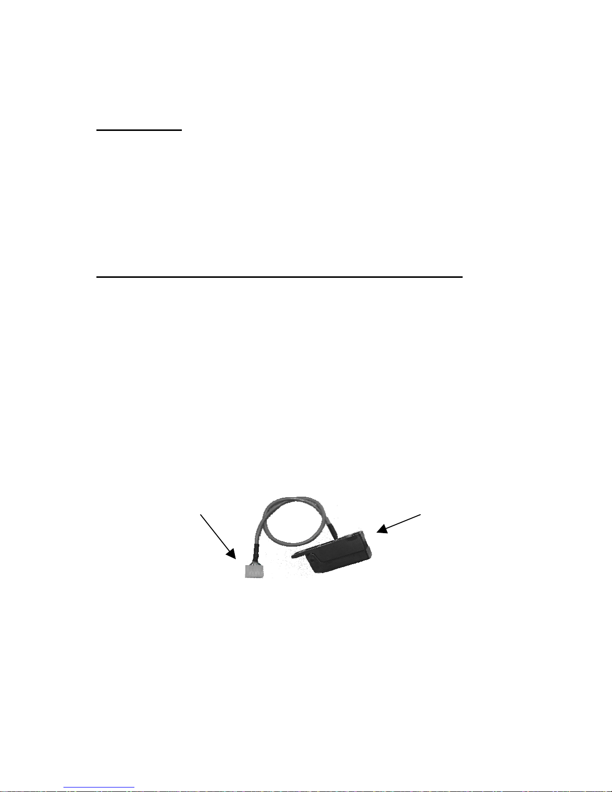
The Sidekick FM universal receiver allows the user to
control most 24VAC irrigation controllers using a
hardwired Permanent Controller Connector or via Direct
Control Interface designed for controllers with an
integrated remote interface.

(800) 275-8558 www.irrigationremotes.com 3
The Sidekick FM Controller Specific Receivers are
designed for specific irrigation controllers with built in
remote interfaces. These receivers are capable operating
all the stations that the irrigation controller has available.
The Sidekick FM 12 (PN: 01015) is a universal receiver
capable of operating up to 12 stations on an irrigation controller.
The Sidekick FM 24 (PN: 1010 & # 01010A) is a universal
receiver capable of operating up to 24 stations on an irrigation
controller.
The Sidekick FM for Rain Bird:(PN: 01018) is a controller
specific receiver designed for Rain Bird:remote port ready
controllers. Note: not all Rain Bird:controllers are remote port
ready.
The Sidekick FM for Hunter:(PN: 01016) is a controller specific
receiver designed for Hunter:ICC and Pro C controllers.
The Sidekick FM for Irritrol:(PN: 01019) is a controller specific
receiver designed for Irritrol:Dial and MC controllers.
The Sidekick FM for Superior Sterling:(PN: 01021) is a
controller specific receiver designed for Superior Sterling:ICC
and Pro C controllers.
The Sidekick FM for Hit:(PN: 01022) is a controller specific
receiver designed for Hit:Logic 2 and Logic 3 controllers.
The Direct Controller interface (DCI) is an accessory designed
for the Sidekick FM universal receivers, which allows the receiver
to operate all of the stations that the controller has available and is
not limited to 12 or 24 stations. The DCI is available for Irritrol:,
Hunter:, and Rain Master:controllers.

(800) 275-8558 www.irrigationremotes.com4
Getting To Know The Transmitter
The Sidekick FM transmitter is
designed to allow the user to operate
one valve/station at a time, making it
ideal for the irrigation maintenance
professional to use for one time
maintenance, seasonal start-ups and
blowouts. To operate the transmitter
the user selects the number of the
valve/station using the keypad followed
by pressing the “ON” button of the
transmitter. The transmitter sends a
proprietary PDTFM signal to the
Receiver turning “ON” or “OFF” a
selected valve as well as the Pump
Start/ Master Valve Station of the
receiver automatically.
When not in use the transmitter reverts to a standby mode,
which is designed for minimal power consumption to extend the
life of the battery. Once any key has been pressed, power is
automatically restored for ten seconds to allow commands to be
sent to the receiver. The Transmitter is designed to operate using
a 9 VDC Alkaline battery. NOTE: Batteries such as general-
purpose 9 VDC batteries will lower the performance of the
transmitter.
Remove the battery door (cover) on the
underside of the transmitter to replace the
battery
Transmitte
r
requires one
9V alkaline battery.

(800) 275-8558 www.irrigationremotes.com 5
The Transmitter Key Pad
To clearly indicate that a key on the keypad has been pressed,
the Sidekick FM Transmitter makes an audible beep.
The Transmitter will beep once when any Number Key is
pressed. When the “ON” or “OFF” key is pressed the
transmitter will beep twice. The first beep indicates that the
transmission is starting, and the second beep indicates that
the transmission has been completed.
Transmitter Operating Instructions
Valve On/Valve Off:
To turn a valve "On" press the desired valve/station number
then press the "On" key. Pressing "Off” will turn the last zone
off.
Error Tone:
A “squawk” error tone indicates that an incorrect series of keys
has been pressed. When the error tone is heard, wait ten
seconds and simply restart the series of commands.
Low Battery Tone:
A rapid sequence of beeps after the transmission tone
indicates low battery power. Replace with a new 9 VDC alkaline
battery.
Example:
To turn on valve 3: 3
ON
To tu
r
no
f
f
valve 3:
OFF

(800) 275-8558 www.irrigationremotes.com6
Installing The Universal Receiver
The Sidekick FM Universal Receiver is designed to work with
most 24 VAC solenoid valve irrigation systems. Using a
permanent controller connector the receiver connects to
individual valves at the controller's terminal strip or directly to
the valve wires at the controller, and bypasses the controller's
functions by directly activating the valves.
Installation Instructions
The housing can be mounted to the right side of the irrigation
controller (Figure 1) or mounted to a wall (Figure 2)
WARNING!
Improper wiring can cause severe damage to the
Receiver and may be a fire hazard. Never con-
nect directly to 110 VAC or damage to the re-
ceiver will occur and you will void your warranty.
FIGURE 1 FIGURE 2

(800) 275-8558 www.irrigationremotes.com 7
1. Use Figure 4 (on the next page) as a pattern to locate the
mounting holes to be drilled through the controller. Drill holes
according to the diameters as shown.
2. Peel backing off gasket (2) and attach it to housing (1) as
shown in figure 3.Peel backing off gasket (3) and attach it to
the inside of housing door (4) as shown in figure 3.
IMPORTANT: For maximum seal, the gasket must fit snug
against the sidewall of the housing door.
3. Insert 1” Allen head cap
screw (5) through the
hole in the housing
door (4) as shown in
figure 3.Slip on retainer
ring (6) approximately
3/8” from the threaded
end of the screw (5).
4. Mount the housing (1)
to the irrigation
controller using two 6-
32 x ¾ Machine
screws, two flat
washers, and two hex
nuts. NOTE: Hardware
is not provided to
mount housing (1) to
wood or sheetrock.
5. Attach the D-Subminiature connector (7) to the inside of the
housing (1) with two 4-40 x 9/16 machine screws. First insert
the loose wire end of the cable (8) through the ½” hole in the
irrigation controller. Important: Orient the D-Subminiature
connector (7) to the inside of the housing (1) as shown in
figure 3. If the orientation of the connector is not as shown in
figure 3, the receiver will not plug in to the connector.
6. The connector is now ready to be wired to the terminal strip
of the irrigation controller. Use the color chart provided on
the other side of the page.
5
2
3
4
1
6
7
8
FIGURE 3

(800) 275-8558 www.irrigationremotes.com8
IMPORTANT: Care should be taken to prevent connecting
any wires of the cable to 110 VAC this will result in damage
to the receiver.
Operating instructions
Plug the receiver directly in the connector as
shown in figure 1. When the receiver is not in
use, close and secure the housing door (4) by
tightening the Allen head screw with a 3-32” Allen
wrench. IMPORTANT: Do not over torque the
Allen head screw, it should be snug.
FIGURE 4
PCC Cable and Housing

(800) 275-8558 www.irrigationremotes.com 9
Installing The Sidekick Receiver
For Rain BirdKControllers
Description
The Sidekick FM System for Rain BirdKcontrollers consist of three
components a transmitter, receiver, and a Permanent Controller
Cable (PCC-RB). The direct controller interface cable and the
receiver are the only components that require installation. Once
the PCC-RB cable is installed, it becomes a permanent access
point for the receiver. To use the Sidekick receiver on more then
one controller simply install another PCC-RB cable in the other
controller.
Permanent Controller Cable (PCC-RB) Installation
1. Follow PCC installation instructions 1-5 on page 7.
2. The connector is now ready to be wired to the terminal strip
of the irrigation controller. Use the color chart provided on
the other side of the page.
3. Connect side “A” of the PCC-RB cable to the remote interface
connector on the Controller. The connector is designed to fit
one way do not force the connector on to the controller.
4. Restore power to the controller.
PCC-RB Cable Part Number: 01387
Molex Connector Side “A” Interface rece
p
tacle Side “B”

(800) 275-8558 www.irrigationremotes.com10
DCI-1 cable Part Number: 01381
Molex Connector Side “A” Interface receptacle Side “B”
Installing The Sidekick Receiver
For IrritrolKControllers
Description
The Sidekick FM System for the IrritrolKDial & MC controllers consist of
three components a transmitter, receiver, and a direct controller interface
cable. The direct controller interface cable and the receiver are the only
components that require installation. Once the DCI-1 cable is installed, it
becomes a permanent access point for the receiver. To use the Sidekick
receiver on more then one controller simply install another DCI-1 cable in
the other controller.
Direct Controller Interface Cable (DCI-1) Installation
1. Disconnect power from the controller to avoid accidentally damaging
the controller.
2. Determine where to install side “B”, the
interface receptacle (See diagram on next
page) of the DCI-1 cable. Use an existing cut
out or the figure to the right for the hole
locations.
3. Use four 6-32 screws, lock washers, and
nuts of the appropriate length and size.
4. Remove any screws securing the controller
face plate to the controller housing.
5. Carefully remove the controller faceplate to reveal the remote
interface connector on the right side of the faceplate.
6. Connect side “A” of the DCI-1 cable to the remote interface
connector on the right side of the faceplate. See diagram on next
page. The connector is designed to fit one way do not force the
connector on to the controller faceplate.
7. Carefully reinstall the controller faceplate.
8. Replace the screws securing the faceplate to the controller.
9. Restore power to the controller.

(800) 275-8558 www.irrigationremotes.com 11
DCI-1 Cable and Sidekick Receiver installation
Connecting the Sidekick FM Receiver
Connect the interface plug to the interface receptacle on the
controller. Twist the plug clockwise until the plug stops. Do not
over tight the plug. See diagram below
Disconnecting the Sidekick FM Receiver
Twist the circular plug in a counterclockwise motion and remove
the plug from the receptacle.

(800) 275-8558 www.irrigationremotes.com12
DCI-1 cable Part Number: 01381
Molex Connector Side “A” Interface receptacle Side “B”
Installing The Sidekick Receiver
SuperiorKSterling Controllers
Description
The Sidekick FM System for the SuperiorKSterling controllers consist
of three components a transmitter, receiver, and a direct controller
interface cable. The direct controller interface cable and the receiver are
the only components that require installation. Once the DCI-1 cable is
installed, it becomes a permanent access point for the receiver. To use
the Sidekick receiver on more then one controller simply install another
DCI-1 cable in the other controller.
Direct Controller Interface Cable (DCI-1) Installation
1. Disconnect power from the controller to avoid accidentally damaging
the controller.
2. Determine where to install side “B”, the
interface receptacle (See diagram on next
page) of the DCI-1 cable. Use an existing cut
out or the figure to the right for the hole
locations.
3. Use four 6-32 screws, lock washers, and
nuts of the appropriate length and size.
4. Remove any screws securing the controller’s
lower faceplate to the controller housing.
5. Carefully remove the controller’s lower faceplate to reveal the remote
interface connector on the right side of the controller.
6. Connect side “A” of the DCI-1 cable to the remote interface
connector on the right side of the faceplate. See diagram on next
page. The connector is designed to fit one way do not force the
connector on to the controller faceplate.
7. Carefully reinstall the controller’s lower faceplate.
8. Replace the screws securing the lower faceplate to the controller.
9. Restore power to the controller.

(800) 275-8558 www.irrigationremotes.com 13
DCI-1 Cable and Sidekick Receiver installation
Connecting the Sidekick FM Receiver
Connect the interface plug to the interface receptacle on the
controller. Twist the plug clockwise until the plug stops. Do not
over tight the plug. See diagram below.
Disconnecting the Sidekick FM Receiver
Twist the circular plug in a counterclockwise motion and remove
the plug from the receptacle.

(800) 275-8558 www.irrigationremotes.com14
DCI-1 cable Part Number: 01381
Molex Connector Side “A” Interface receptacle Side “B”
Installing The Sidekick Receiver
HitKLogic 3 & 2 Controllers
Description
The Sidekick FM System for the HitKLogic 3 & 2 controllers consist of
three components a transmitter, receiver, and a direct controller interface
cable. The direct controller interface cable and the receiver are the only
components that require installation. Once the DCI-1 cable is installed it
becomes a permanent access point for the receiver. To use the Sidekick
receiver on more then one controller simply install another DCI-1 cable in
the other controller.
Direct Controller Interface Cable (DCI-1) Installation
1. Disconnect power from the controller to avoid accidentally damaging
the controller.
2. Determine where to install side “B”, the
interface receptacle (See diagram on next
page) of the DCI-1 cable. Use an existing cut
out or the figure to the right for the hole
locations.
3. Use four 6-32 screws, lock washers, and
nuts of the appropriate length and size.
4. Remove any screws securing the controller’s
lower faceplate to the controller housing.
5. Carefully remove the controller’s lower faceplate to reveal the remote
interface connector in the center of the controller.
6. Connect side “A” of the DCI-1 cable to the remote interface
connector in the center of the faceplate. See diagram to the right.
The connector is designed to fit one way do not force the connector
on to the controller faceplate.
7. Carefully reinstall the controller’s lower faceplate.
8. Replace the screws securing the lower faceplate to the controller.
9. Restore power to the controller.

(800) 275-8558 www.irrigationremotes.com 15
DCI-1 Cable and Sidekick Receiver installation
Connecting the Sidekick FM Receiver
Connect the interface plug to the interface receptacle on the
controller. Twist the plug clockwise until the plug stops. Do not
over tight the plug. See diagram below.
Disconnecting the Sidekick FM Receiver
Twist the circular plug in a counterclockwise motion and remove
the plug from the receptacle.

(800) 275-8558 www.irrigationremotes.com16
DCI-1-H cable Part
Number: 01386
Molex Connector Side “A” Interface receptacle Side “B”
Installing The Sidekick Receiver
Hunter
K
Controllers
Description
The Sidekick FM System for the HunterKcontrollers consist of three
components a transmitter, receiver, and a direct controller interface
cable. The direct controller interface cable and the receiver are the only
components that require installation. Once the DCI-1-H cable is installed,
it becomes a permanent access point for the receiver. To use the
Sidekick receiver on more then one controller simply install another DCI-
1-H cable in the other controller.
Direct Controller Interface Cable (DCI-1-H) Installation
1. Open the front panel door of the controller housing.
2. Disconnect power from the controller to avoid accidentally damaging
the controller.
3. Determine where to install side “B”, the
interface receptacle (See diagram on next
page) of the DCI-1-H cable. Use an
existing cut out or the figure to the right for
the hole locations.
4. Use four 6-32 screws, lock washers, and
nuts of the appropriate length and size.
5. Secure the interface receptacle to the
cutout or hole location.
6. Connect side “A” of the DCI-1-H cable to the Main Control module.
See diagram on next page.
7. Connect the Red wire to the terminal Marked “AC” above the
terminal marked “GND”.
8. Connect the White wire to the terminal marked “AC” below the
terminal marked “REM”.
9. Connect the Blue wire to the terminal marked “REM”
10. Close the front panel door of the controller housing.
11. Restore power to the controller.

(800) 275-8558 www.irrigationremotes.com 17
DCI-1-H Cable and Sidekick Receiver installation
Sidekick FM Receiver
Connect the interface plug to the interface receptacle on the
controller. Twist the plug clockwise until the plug stops. Do not
over tight the plug. See diagram below.
Disconnecting the Sidekick FM Receiver
Twist the circular plug in a counterclockwise motion and remove
the plug from the receptacle.
The Blue wire is connected to the terminal marked “REM”
The White wire is connected to the terminal marked “AC”
The Red wire is connected to the terminal marked “AC”
If you receive an “ERR” message on the LCD display of the
controller after wiring the connector as shown, then reverse
the positions of the White and Red wires

(800) 275-8558 www.irrigationremotes.com18
Installing The Direct Controller
Interface
Description
The Direct Controller interface (DCI) is an accessory designed
for the Sidekick FM universal receivers, which allows the receiver
to operate all of the stations that the controller has available and is
not limited to 12 or 24 stations. The DCI is available for Irritrol:,
Hunter:, and Rain Master:controllers. The DCI converts the
control logic of the Universal Receiver to match the control logic of
the controller. This expands the capability of the TRC Commander
or Sidekick to operate as many stations as the controller has
available, rather than limitations of 12, 24, or 32 stations.
Installation
DCI-1 to controller
Installation
Refer to page 10 of this
manual.
DCI-1-H to Controller
installation
Refer to page 16 of this
manual.
DCI-2 to Universal Receiver
Installation
After the DCI-1 installation is
complete. All that remains is to
connect the DCI-2 and the universal receiver to the DCI-1. The
first step is to connect the 37 PIN D-sub connector of the DCI-2 to
the Universal receiver. Then connect the 9 PIN barrel connector to
the DCI-1 installed in the controller.
NOTE: ALWAYS CONNECT THE DCI-2 TO THE RECEIVER
FIRST OTHERWISE THE RECEIVER WILL BE DAMAGED
INTERNALLY AND NEED TO BE REPAIRED.

(800) 275-8558 www.irrigationremotes.com 19
Trouble Shooting Chart
My Transmitter does
not beep.
Check the battery. Using a
voltmeter or a battery tester, test
the battery voltage. Replace the
battery if the voltage is below
6.8 volts.
My Transmitter is
beeping rapidly.
Rapid beeps after a transmiision
is an indication the the battery
voltage is low. Replace the
battery with a new high quality 9
VDC Alkaline battery.
My Sidekick system is
not getting any range
See antenna installation tips for
proper antenna installation.
My Sidekick is turning
off after 20 minutes.
The Receiver has a default 20
minute shut off. When a valve is
activated it remains on for 20
minutes and shuts off
My Receiver is not
getting any power.
If receiver power light is not on
check to see that the remote
interface cable is installed
properly and the controller has
power.
For Technical Support call 800-275-8558 Monday through Friday
7AM - 4PM PST. All goods returned to TRC Irrigation Remotes
must be accompanied with a RMA. Please use our toll free # to
obtain a RMA.
Products returned without an RMA will be
charged a $150 flat rate, regardless of
problem.
Table of contents
Other TRC Remote Control manuals