TRE i SYSTEMS EG-3 User manual
SISTEMA DI SICUREZZA MULTIFUNZIONE
SISTEMA DI SICUREZZA MULTIFUNZIONESISTEMA DI SICUREZZA MULTIFUNZIONE
SISTEMA DI SICUREZZA MULTIFUNZIONE
con TRASMISSIONE SMS, MMS e E
con TRASMISSIONE SMS, MMS e Econ TRASMISSIONE SMS, MMS e E
con TRASMISSIONE SMS, MMS e E-
--
-mail
mailmail
mail
MULTIFUNCTION SECURITY SYSTEM with
MULTIFUNCTION SECURITY SYSTEM withMULTIFUNCTION SECURITY SYSTEM with
MULTIFUNCTION SECURITY SYSTEM with
SMS, MMS and E
SMS, MMS and ESMS, MMS and E
SMS, MMS and E-
--
-mail TRANSMISSION
mail TRANSMISSION mail TRANSMISSION
mail TRANSMISSION
®

Summary Page
Summary Page Summary Page
Summary Page
INTRODUCTION
1.0 Description................................................................................................20
1.0 Standard kit................................................................................................20
1.2 Getting to know the product........................................................................21
INSTALLATION
2.0 Where to install..........................................................................................22
2.1 Start-up procedure .....................................................................................23
2.2 Functional LED indicators .........................................................................23
2.3 Keychain transmitter used with EG-3..........................................................23
EG-3HW (HARDWIRE)
3.0 Installation of EG-3 as EG-3HW with hardwire control panel .....................24
3.1 Hardwire connections to terminal block......................................................24
3.2 Activation and memorizing PEG-1 transmitter on the EG-3HW ...................25
3.3 Wireless indoor or outdoor siren installation in mode EG-3HW...................25
EG-3WL (WIRELESS)
4.0 Installation of EG-3 as EG-3WL with a wireless “Pegaso” panel ..............26
4.1 Activation and memorizing EG-3 to function in mode EG-3WL ...................27
EG-3SL (STAND-ALONE)
5.0 Installation of EG-3 to function in mode EG-3SL........................................28
5.1 Activation and memorizing the “Pegaso” codes in the EG-3SL....................29
EG-3SLM (STAND-ALONE MASTER)
6.0 Installation of EG-3 to function in mode EG-3SLM.....................................30
6.1 How to memorize all slave sensors when in mode EG-3SLM ......................31
PROGRAMMING & COMMANDS
7.0 Programming and setting of SMS command messages ...............................32
7.1 Real time control of EG-3 through SMS messages ......................................33
7.2 Procedure to totally cancel the EG-3 memory.............................................34
NORMAL USE
8.0 Normal functioning sequence in the 4 installation modes ...........................35
8.1 Listen-in and 2 way communication functions.............................................35
8.2 EG-3 real time control of the protected area...............................................35
8.3 How to enter into EG-3 manteinance mode.................................................36
PRECAUTIONS
9.0 Precautions to observe...............................................................................36
10.0 Technical characteristics........................................................................36
Page 19
EG-3 Instruction manual
ENGLISH

INTRODUCTION
TRE I SYSTEMS thanks you for having selected the award winning Eg-3 for your personal
protection. This product offers the end user the latest and most modern data transmission
technology present on the market today. With the installation of an EG-3 it is possible, in real time,
to transmit SMS messages and MMS images to cellular phones and e-mail addresses.
Before starting the installation, we suggest that you read carefully the contents of this
manual.
1.0 Description
The EG-3 is a product that may be installed in four different modes of operation and based on how it
has been installed, will protect your home, office, store, factory etc. by capturing images of the
events taking place and through its built-in GPRS 2G module, SMS telephone dialler and CMOS
camera can transmit 3 SMS messages and 5 images to 4 memorized telephone numbers and to 2
E-mail addresses.
The EG-3 has been designed to function in 4 different modes to satisfy the end user needs:
1. Installation as EG-3HW: this is installed with a hardwire installation (new or existing).
2. Installation as EG-3WL: this is installed with a wireless “Pegaso” protocol control panel.
3. Installation as EG-3SL: this is installed as a stand-alone unit. (protects a single area)
4. Installation as EG-3SLM: this is installed as a wireless control panel and can self learn 20 slave
sensor and keychain transmitters. Sends SMS message of “Tamper” and “Low Battery”. In this
mode, a full wireless installation can be made without having to install another control panel. The
EG-3 in EG-3SLM mode becomes your control panel, telephone dialler and camera all in
one.
Depending on the mode the EG-3 is installed, it can:
1. Add protection features and upgrade the technology in existing or new hardwire installation.
2. Be installed and function with an existing wireless control panel and thus add additional
protection features and upgrading the technology of existing or new installations.
3. Be installed as a stand-alone and can protect a single area with the most modern data
communication technology available on the market today.
4. Act as a full wireless control panel, capable of protecting 20 wireless zones and transmit all
information and collected data using SMS, MMS and GPRS technology.
1.1 Standard kit
EG-3 HW e EG-3 WL
√
EG-3 (1pc.)
√
2 Amp. Power supply (1pc.)
√
Back-up battery (1pc.)
√
Swivel bracket (1pc.)
√
Antenna GSM / GPRS (1pc.)
√
Micro SD memory card (1pc.)
√
Mounting screw bag (1pc.)
√
Instruction manual (1pc.)
√
Warranty card (1pc.)
OPTIONAL
√
PEG-1 Waterproof keychain transmitter
normally used for Medical Distress Alarm.
EG-3 SL e EG-3 SLM
√
EG-3 (1pc.)
√
2 Amp. Power supply (1pc.)
√
Back-up battery (1pc.)
√
Swivel bracket (1pc.)
√
Antenna GSM / GPRS (1pc.)
√
Micro SD memory card (1pc.)
√
Mounting screw bag (1pc.)
√
PEG –3 keychain transmitters (2pc.)
√
Instruction manual (1pc.)
√
Warranty card (1pc.)
OPTIONAL
√
All Wireless “Pegaso” Sensors, see TRE
TRETRE
TRE
-
--
-i SYSTEMS
i SYSTEMSi SYSTEMS
i SYSTEMS
price list for more information.
Page 20 EG-3 Instruction manual
ENGLISH
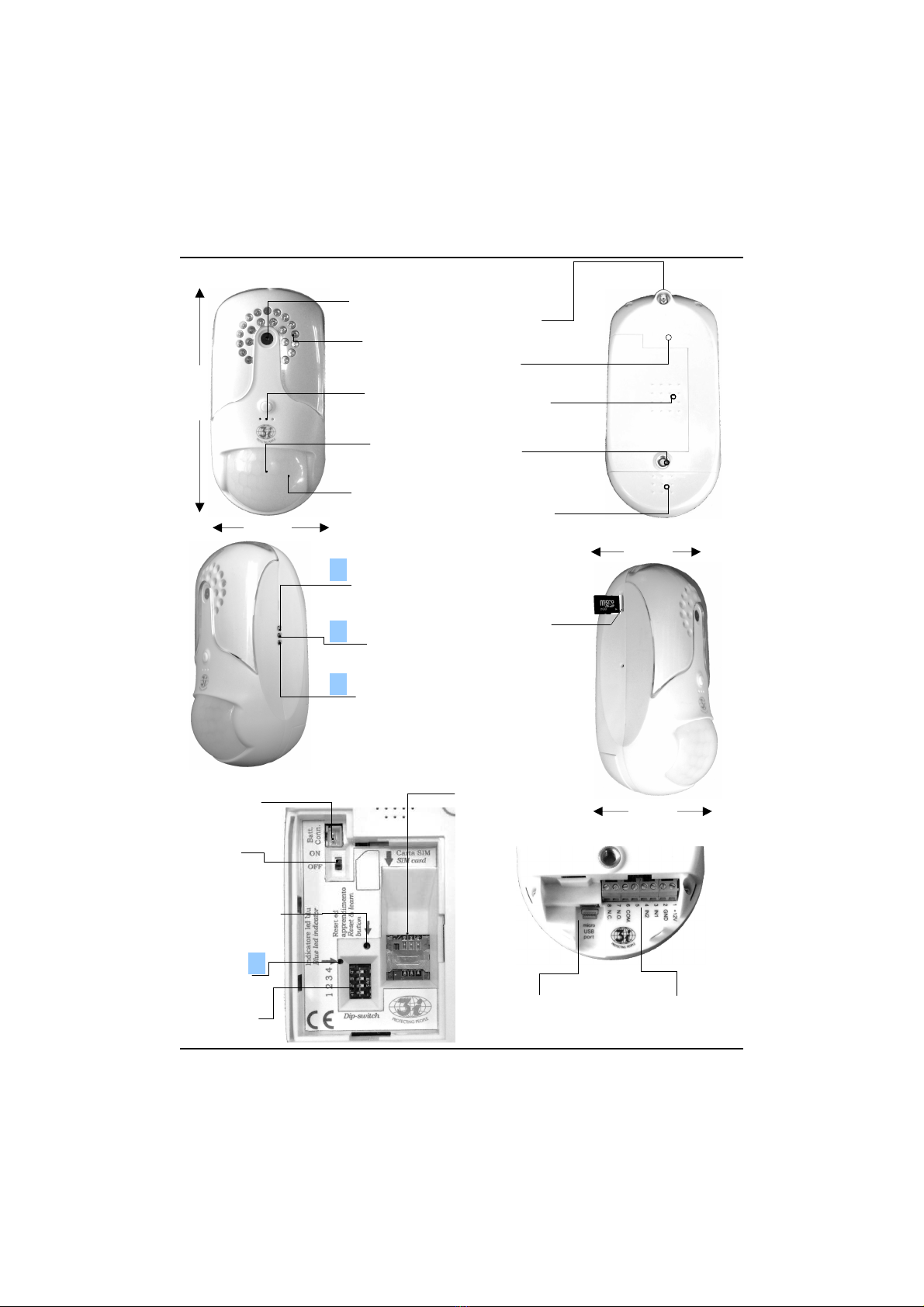
1.2 Getting to know the product
Power LED &
GPRS / GSM
Presence
Arming LED
GPRS / GSM
Field LED
GSM/GPRS
Antenna
connector
Battery
compartment
Terminal block
compartment
Swivel
bracket
Speaker
SIM card
holder
Dip-switch
Battery
connection
On / Off
switch
Reset and
sensor self
learning button
Blue LED
indicator
Hardwire
terminal
Micro USB
connector
1
2
3
4
CMOS Camera
Night vision
LEDS
Microphone
Infrared
Sensor
Walk-test LED
(behind lens)
78 mm
168 mm
Micro SD card
compartment
60 mm
69 mm
Page 21
EG-3 Instruction manual
ENGLISH

INSTALLATION
2.0 Where to install
To ensure that the EG-3 functions correctly, it is important to select a good installation location.
You must therefore verify that the installation location has the following characteristics:
• The EG-3 system is manufactured for indoor use only.
• The surface to which it is fixed must be sturdy and not have any form of vibration.
• In the immediate area in which the EG-3 is installed there must not be sources of heat or air
conditioning that can create air movement.
• Both the incorporated CMOS camera and PIR sensor must not be put in direct sun light or
any other form of light source that may negatively effect the camera’s image.
• To obtain the best range for both camera and PIR sensor, it is best to install in an open space
area.
• Installation in areas of high furniture concentration may interfere with both the PIR and
images taken by the camera.
• Before installation, using a normal cellular telephone, check the GPRS field strength in the ar-
ea you wish to protect. Select an area that has good GPRS reception.
• Avoid areas with high frequency transmission disturbances.
• Avoid areas with very high humidity or that are over heated.
PIR WORKING RANGE
The EG-3 must be installed at a height of 2.00 to
2.20 meters. in order that the PIR sensor may have
a minimum range of 0.40 meters and maximum
range of 12.00 meters. See figure on right.
On the EG-3 is assembled a specially designed
Fresnel lens with 102 zones and has a 90°
horizontal and 110°vertical working angle. You must
also be aware that the sensitivity of a PIR sensor
reacts more to an object crossing the facets of
protection than an object moving toward or away
from these same facets.
WALK-TEST
Behind the Fresnel lens, there is a WALK-TEST,
LED that lights when movement takes place in the protected area. When the EG-3 is disarmed the
walk test LED will function and allows the installer to understand the pattern of coverage, however,
no alarm trigger will be triggered. When the EG-3 is armed and only after the SMS trigger messaged
has been sent, any movement, in the protected area, will be indicated by the red LED and will also
trigger an alarm. During an alarm trigger the EG-3 will first send one of the 3 memorized SMS
messages and then send 5 images by MMS to the memorized telephone numbers and E-mail
addresses and also memorize another 32 images on the Micro-SD card incorporated.
2.20 m
2.00 m
0,40 m 12,00 m
90°
110°
SIDE VIEWTOP VIEW
Page 22 EG-3 Instruction manual
ENGLISH

2.1 Start-up procedure
Before inserting the SIM card, make sure that there is no PIN code, you may use a normal
cellular telephone to verify this. In case a PIN code exists, it must be unlocked.
The Micro SD card supplied with the EG-3 has nothing memorized on board.
In order to verify this, it must be removed and inserted into Micro SD card reader.
To open the battery compartment on the back side of the EG-3, you must apply downward
pressure and have the cover slide towards the left.
The terminal block compartment can be opened the same way.
Insert the SIM card as shown in the battery compartment. Also insert the Micro SD card, if not
already inserted. This card is normally already factory installed.
Make sure that the “ON/OFF” switch located in the battery compartment is in “OFF” position.
With the dip-switch, select the functioning mode in which you would like to install the EG-3.
You may select from one of the 4 configurations seen in sections 3.0 to 6.0.
2.2 Functional LED Indicators
The LEDS positioned on the right of the EG-3 (see page 4), have the following functions:
• The LED (1) indicates the Power and GPRS/GSM field presence. When the EG-3 is powered
up, this LED will become first Red (in presence of GSM field) and if there is presence of GPRS
field, it will then become Green.
• The LED (2) will light up green when the EG-3 is armed, if the unit is disarmed with the
keychain transmitter it will go “OFF”.
• The LED (3) will indicate if the GPRS module is functioning correctly. If it will flash slowly, the
GPRS module is connected to the network. If it will flash rapidly, no connection is present.
• The blue LED (4), located inside of the battery compartment is used to indicate:
Initialization process;
Reset of stored memory;
Self learning of the “Pegaso” radio codes received from the sensors and keychain
transmitters installed in mode EG-3HW, EG-3SL and EG-3SLM.
2.3. Keychain transmitters used with EG-3
PEG-1 WATER PROOF
HOLD-UP or PANIC
TRIGGER BUTTON
LED TRANSMIS-
SION INDICATOR
PEG-3
HOLD-UP or PANIC
TRIGGER BUTTON
LED TRANSMIS-
SION INDICATOR
ARM and DISARM
BUTTON
NOT USED
Page 23
EG-3 Instruction manual
ENGLISH

EG-3HW (HARD-WIRE)
3.0 Installation of EG-3 as EG-3HW with hardwire control panel
The EG-3HW will act as a normal sensor if installed with a hard-wired control
panel. The switch 2 and 4 of the dip-switches, located in the battery compart-
ment, seen on the right, must be set as shown in fig. 1 in order to activate the
hardwire mode. After this the EG-3HW must be initialized. Be sure that the “on/
off” switch is in “OFF” position. Connect first the battery and then, based on the
polarity, the power supply wires to terminals 1 and 2 as described in section
3.1 below. Press continuously the reset/learn button located in the battery com-
partment. Switch to “ON” position the “on/off” switch and after about 8 seconds
the EG-3HW will emit 3 beeps. Release the reset button and after 45 se-
conds another 2 beeps will be emitted. This will confirm that the EG-3HW
has been successfully initialized.
Note: When powered up, the RED LED 1 will light and immediately after
if GPRS signal is present this same LED will become GREEN.
The EG-3HW may be triggered with a positive or negative trigger output from
the control panel. The EG-3HW has two trigger inputs IN-1 for fire and IN-2 for
Burglary. The dip switch seen on the right must be set as shown in fig. 2 if the
control panel has a positive trigger outputs and as shown in fig. 3 if the control
panel has negative trigger outputs.
The terminal block inputs (3) and (4) that correspond to the inputs IN-1 and
IN-2 are shown below in section (See 3.1)
In addition in the EG-3HW MODE, there is available also a panic zone that
may be triggered with a water proof keychain transmitter PEG-1 (supplied
optional). If the burglary, fire or panic alarm is triggered, the programmed SMS message will be sent
to the 4 memorized telephone numbers. After the SMS message is sent, by the EG-3HW, the
on-board PIR sensor will become active and if movement is sensed, it will send 5 MMS IMAGES of
the protected area to the 4 programmed telephone numbers and 2 E-mail addresses. During all
alarm triggers, (burglary, fire and panic), the EG-3HW will transmit an R.F. alarm trigger signal to the
wireless outdoor “Pegaso” series siren if installed.
TLM-7 SOLARIS See Section 3.3
ALL PROGRAM SETTINGS INSTRUCTIONS CAN BE SEEN IN SECTION 7.0
3.1 Hardwire connections to terminal block
In all modes the EG-3 must receive is power from the furnished power supply. Other forms of
power may cause damage to the unit and as a consequence all warrantee benefits will be lost.
Make all connections as shown below:
1. Red cable from the power supply (positive).
2. Black cable from power supply (negative), In the EG-3HW mode,
connect also a negative from the control panel.
3. Fire Trigger IN-1 (position switch 1 and 2 in positive or negative as
shown in Fig. 2 or 3 above). To be used only in EG-3HW MODE.
4. Burglary Trigger IN-2 (position switch 1 and 2 in positive or negative
as shown in Fig. 2 or 3 above). To be used only in EG-3HW MODE.
5. Not used
6. Common relay output (remotely activated with SMS command)
7. Normally open dry contact relay output.
8. Normally closed dry contact relay output.
USB PORT NOT YET IN USE.
Note: Terminals 7 & 8 above are activated by SMS command (see par.7.1)
1 2 3 4
Fig. 1
HARDWIRE MODE
+
-
1 2 3 4
Fig. 2
1 2 3 4
Fig. 3
POSITIVE TRIGGER
NEGATIVE TRIGGER
+
-
+
-
1 +12V
2 GND
3 IN 1 fire
4 IN 2 burg.
5 Not Used
6 COM.
7 N.O.
8 N.C.
USB port
Page 24 EG-3 Instruction manual
ENGLISH

3.2 Activation and memorizing PEG-1 “Pegaso” on the EG-3HW
In the hardwire mode, it is possible to memorize in the EG-3HW memory a maximum of 20 PEG-1
wireless water proof keychain transmitter normally used to trigger a PANIC or MEDICAL DISTRESS
alarm To memorize the PEG-1, follow the below instruction:
1. Press and hold down the RESET/LEARN button located in the battery compartment until the
blue LED lights. Release the button.
2. Press the PEG-1 transmitter to generate an R.F. transmission. The blue LED will go “off”. This
indicates that the EG-3 has received the signal and that the code has been memorized.
3. You may memorize a maximum 20 PEG-1 transmitters. So if you wish to memorize another
Keychain transmitter, repeat the procedures 1 and 2 above.
If the blue LED starts to flash, this will indicate one of two conditions:
1. Two flashes indicate that the PEG-1 has been already memorized.
2. Three flashes will indicate that the EG-3HW memory is full.
If you wish to cancel the memory, you must press the RESET/LEARN button and keep it pressed
constantly. The blue LED will light and after 7 seconds the LED will go “OFF”.
After this the button may be released. All “Pegaso” codes memorized have been cancelled.
The EG-3 is factory supplied without any codes memorized on-board.
3.3 Wireless indoor or outdoor siren installation in mode EG-3HW
In this mode it is possible to install an indoor or outdoor wireless “Pegaso” siren (TLM 18VRP,
TLM-21VRP or TLM-7 SOLARIS). The sounds emitted by these sirens are based on the alarm
trigger received. This will allow the installer or end user to understand in real time the alarm that has
been triggered. Burglary, Fire, Panic or Medical Distress.
You must note that in the mode EG-3HW it is not possible to silence the siren once the alarm is
trigger. The siren will sound for 100 seconds (120 seconds with the TLM-7 SOLARIS) and au-
tomatically reset itself after the alarm times has expired.
To program a “Pegaso” wireless siren with the EG-3HW you must follow the siren instructions. (see
in section 5.0.) To verify if the siren has been correctly installed, run the following tests:
1. Arm the control panel.
2. Have the control panel trigger through input IN-2.
3. The EG-3HW will sends an alarm trigger command to the siren.
4. After the siren has ended its alarm cycle, it will stop sounding and automatically reset itself.
Once terminated the initialization procedure and choice of trigger command, you may position the
battery so that the battery compartment may be closed. Also the terminal block compartment may be
closed. At this point you may fix the GSM/GPRS antenna and select a position on the wall to install
the EG-3 swivel bracket.
After this, you may proceed with the setting of the SMS messages, Telephone numbers and
E-mail addresses as described in section 7.0.
With remote SMS commands, it is possible to request form the EG-3HW in armed status:
1. To change, for 5 seconds, the state of the on-board relay contact, outputs (COM, NO, NC).
May be used to arm/disarm the control panel or for home automation (see section 3.1).
2. To enter into listen-in or two way communication function and hear what is taken place in the
protected area (see section 8.1).
3. To request that images be sent as periodic control of the protected area (see section 7.0).
4. To change the memorized telephone numbers and E-mail addresses (see section 7.0).
Page 25
EG-3 Instruction manual
ENGLISH

EG-3WL (WIRELESS)
4.0 Installation of EG-3 as EG-3WL with a wireless “Pegaso” panel
In this mode, the EG-3 will receive all commands from the “Pegaso” control
panel installed and will act similar to a slave sensor to this panel. You must
set the dip-switch located in the back-up battery compartment as shown in
fig. 4, on the right. Be sure that the “on/off” switch located in the battery
compartment is in “OFF” position. Connect based on the polarity the 2 output
wires of the power supply to terminals 1 and 2 (see section 3.1). After having
set the dip-switch in EG-3WL mode, the unit must be initialized. Press
continuously the reset button located in the battery compartment. Switch to
“ON” the “on/off” switch and after 8 seconds the EG-3WL will emit 3 beeps.
Release the reset button and after another 45 seconds 2 beeps will be
emitted. This confirms that the EG-WL has been successfully initialized.
Note: During this initialization period the RED LED 1 will light and immediately
after. If GPRS signal is present this same LED become green.
The EG-3WL, once programmed as indicated in section 4.1, will be armed and disarmed with a
radio command signal from the control panel.
Three wireless alarm trigger signals, will be sent to the EG-3WL from the “Pegaso” wireless control
panel, (Burglary, Fire or Panic) the EG-3WL will send to the 4 memorize telephone numbers the
SMS message memorized for the event triggered. After the SMS message has been sent, the
EG-3WL on-board PIR sensor will become active and if movement is sensed in the protected area,
5MMS images will be sent to the 4 memorized telephone numbers and to 2E-mail addresses.
The EG-3WL will also memorize on the micro SD card 32 additional images. These images may be
seen by removing the SD card from the EG-3WL and placing it in an SD card reader.
Once the EG-3WL is triggered, if in this area protected by the unit’s on-board PIR sensor, no
movement is detected, no MMS or E-mail images will be sent.
To Program SMS messages, Telephone Numbers and E-mail addresses see section 7.0.
With remote SMS commands, it is possible to request form the EG-3WL in armed status:
1. To change, for 5 seconds, the state of the on-board relay contact, outputs (COM, NO, NC).
May be used to arm/disarm the control panel or for home automation (see section 3.1).
2. To enter into listen-in or two way communication function and hear what is taking place in the
protected area (see section 8.1).
3. To request that images be sent as periodic control of the protected area (see section 7.0).
4. To change the memorized telephone numbers and E-mail addresses (see section 7.0).
1 2 3 4
Fig. 4
EG-3WL MODE
+
-
Page 26 EG-3 Instruction manual
ENGLISH

4.1 Activation and memorizing EG-3 to function in mode EG-3WL
In mode EG-3WL (wireless mode) the unit will receive all commands from the “PEGASO” wireless
control panel with which it is installed. The EG-3WL must memorize the same “Pegaso” transmission
code that the control panel sends to the wireless indoor or outdoor siren.
This is how it is done:
Program EG-3WL with VP-6N or VP-7NT wireless control panels
1. Press the RESET/LEARN button located in the battery compartment and wait until the blue LED
lights. Then release this button.
2. Make sure that VP-6N and VP-7NT are “OFF”. Wait 5 seconds and rotate the key into ”ON”
position. The panels will automatically transmit the “Pegaso” codes to the EG-3WL and the blue
LED will go “OFF”. This is a confirmation that the unit has learned the “Pegaso” code.
Program EG-3WL with the Phoenix control panel
1. Press the RESET/LEARN button located in the battery compartment and wait until the blue LED
lights. Then release the button.
2.
Arm the PHOENIX control panel. The necessary “Pegaso” codes will be sent to the EG-3WL and
the blue LED will go “OFF”. This indicates that the code has been learned by the EG-3WL.
Program EG-3WL Dualcom-8 control panel
1. Press the RESET/LEARN button located in the battery compartment and wait until the blue LED
lights. Then release the button.
2. Arm the Dualcom-8 with its keypad. The necessary “Pegaso” codes will be sent to the EG-3WL
and the blue LED will go “OFF”. This is an indication that the EG-3WL has learned the code.
Program EG-3WL with the VISION FR control panel
1. The control panel must have the option of using a wireless siren selected as “YES”.
2. Arm the control panel with the keychain transmitter and immediately after press the
RESET/ LEARN button of the EG-3WL located in the battery compartment until the blue LED
lights then release the button. .
3. When the blue LED goes “OFF” the EG-3WL will have learned the “Pegaso” code sent by the
control panel.
While memorizing the EG-3WL with any of the above control panels, it is important that non
of the sensor installed with any of the above installations trigger an alarm signal. This will
cause radio frequency interference and will not allow you to properly program the EG-3WL.
After having programmed the EG-3WL with 1 of the above control panel and you note that the blue
LED starts to flash, this will indicate one of two conditions:
1. Two flashes indicate that the control panel code is already memorized in the EG-WL memory.
2. Three flashes indicate that the EG-3WL memory is full.
At this point if the memory is full, to cancel, you must: Press the RESET/LEARN button and keep it
pressed constantly. The blue LED will light and after about 7 seconds the LED will go “OFF”. After
this the button may be released. The memory has been cancelled.
THE EG-3 IN ALL MODES is factory supplied without anything memorized on-board.
Once finished with the initialization and memorization procedures, you may position the battery and
close the battery and terminal block compartments. At this point fix the GSM/GPRS antenna and
select a position on the wall to install the EG-3 swivel bracket.
Now you may proceed with the setting of the SMS messages, Telephone numbers and E-mail
addresses as described in section 7.0.
Page 27
EG-3 Instruction manual
ENGLISH

EG-3SL (STAND-ALONE)
5.0 installation of EG-3 to function in mode EG-3SL
In this mode the EG-3SL will functions as a stand-alone control unit and will
protect a single area. Make sure that the “on/off” switch located in the battery
compartment is in “OFF” position. Set the dip-switch located in the back-up
battery compartments as shown in fig. 4 to the right. Once set, the EG-3SL
must be initialized. Connect the power supply cables based on the polarity to
the terminals 1 and 2 as shown in section 3.1. and plug it into the mains. Press
continuously the RESET/LEARN button located in the battery compartment and
switch to “ON” position the “on/off” switch. After 8 seconds the EG-3SL will
emit 3 beeps. Release the RESET/LEARN button and after another 45 se-
conds an additional 2 beeps will be heard. This confirms that the EG-3SL has
been successfully initialized.
Note: During this initialization period the RED LED (1) will light and immediately
after. If GPRS signal is present this same led become green.
To arm and disarm the EG-3SL it is necessary to program at least one PEG-3 keychain transmitter
(see section 5.1). To arm press the button on the upper left of the PEG-3. The EG-3SL will emit 1
beep and after an exit time of 25 seconds, it will be fully armed. To disarm you must press the same
button and 2 beeps are emitted. This indicates that the EG-3 has been disarmed.
Once the EG-3SL is armed, the on-board PIR becomes active and if triggered, an SMS alarm
message will be sent to the 4 memorized telephone numbers and an R.F. alarm trigger signal will be
sent to the outdoor wireless siren.
Immediately after the SMS message is sent the EG-3SL will proceed to send 5 images of the
protected area to the same 4 telephone numbers and to 2 E-mail addresses.
How to program the SMS messages, telephone numbers and E-mail addresses can be seen in
section 7.0.
In addition the EG-3SL will memorize 32 images on a micro SD card which must be removed from
the unit and placed into an SD card reader to view.
With remote SMS commands, it is possible to request from the EG-3SL in armed status:
1. To change, for 5 seconds, the state of the on-board relay contact, outputs (COM, NO, NC).
May be used to arm/disarm the control panel or for home automation (see section 3.1).
2. To enter into listen-in or two way communication function and hear what is taking place in the
protected area (see section 8.1).
3. To request that images be sent as periodic control of the protected area (see section 7.0).
4. To change the memorized telephone numbers and E-mail addresses (see section 7.0).
Once the EG-3SL is triggered, it will send first the memorized SMS message indicating the type of
alarm triggered (Burglary, Fire or Panic/Medical Distress). It will send also send a radio signal
transmission to the indoor or outdoor siren, if installed, that will sound based on the trigger signal
received. The EG-3SL will then proceed to send the MMS and E-MAIL images to the memorized tel-
ephone numbers and e-mail addresses.
1 2 3 4
Fig. 5
MODALITA’ SL
+
-
Page 28 EG-3 Instruction manual
ENGLISH

5.1 Activation and memorizing the “Pegaso” codes in the EG-3SL
In this mode you may memorize a maximum of 20 PEG-3 keychain transmitters which allow you to
Arm or Disarm the EG-3SL and trigger the Panic Alarm.
It is also possible to memorize the PEG-1 waterproof keychain transmitter but this can be used only
to trigger the Panic or Medical Distress alarm. To program PEG-1 or PEG-3, See below:
1. Press the RESET/LEARN button until the blue LED lights up. Release the button.
2. Press a button on the PEG-3 or PEG-1 to create R F transmission. The blue LED will go off.
3. If you wish to code additional transmitters, repeat 1 and 2 above (max. 20 may be programmed).
After or during the above programming operation, if the blue LED starts to flash, this will indicate one
of two conditions:
1. Two flashes indicate that the PEG-3 or PEG-1 has been already memorized.
2. Three flashes indicate that the EG-3SL memory is full.
The EG-3 is factory supplies without anything memorized on-board
TO CANCEL THE SELF LEARNING MEMORY
If the memory is full , it may be cancelled by: Pressing the RESET/LEARN button and keep it
pressed constantly. The blue LED will light and after about 7 seconds the LED will go “off”.
After this the button may be released. The self learning memory has been totally cancelled.
The EG-3 is factory supplied without anything memorized on-board.
TO MEMORIZE A “PEGASO” WIRELESS SIREN
To code a wireless “Pegaso” outdoor siren with the EG-3SL, follow the programming
instructions in section 5.0 supplied with the siren. In this mode it is possible to install an indoor
or outdoor wireless siren (TLM 18VRP, TLM-21 VRP or TLM-7 SOLARIS). The sounds emitted by
these sirens are different based on the alarm trigger received. (burglary, fire or panic/medical
distress). This will allow the installer or end user to understand in real time the type of alarm that has
been triggered. After having coded the wireless siren with the EG-3SL, run the following tests to
understand if the siren has been correctly installed.
1. With the PEG-3 keychain transmitter, arm the EG-3SL. (one beep will be heard from EG-3SL &
Siren as confirmation)
2. Trigger the EG-3SL so that an alarm trigger transmission will be sent to the outdoor siren.
3. The siren will start sounding the first cycle based on the alarm triggered.
4. Disarm the EG-3SL with the PEG-3 Transmitter (two beeps will be heard from the EG-3SL &
Siren). The siren will stop sounding.
Once finished with the initialization procedure, you may position the battery so that the battery
compartment may be closed. Also the terminal block compartment may be closed and you may
proceed to fix the GSM/GPRS antenna and select a position on the wall to install the EG-3SL swivel
bracket.
Now you may proceed with the settings of SMS messages, Telephone numbers and E-mail
addresses as described in section 7.0.
Page 29
EG-3 Instruction manual
ENGLISH

EG-3SLM (STAND-ALONE MASTER)
6.0 installation of EG-3 to function in mode EG-3SLM
In the mode EG-3SLM, the EG-3 will function in the same way as a
wireless “PEGASO” control panel.
To activate the EG-3SLM in this mode, set the dip switch as shown in fig. 4 to
the right. Once set the EG-3SLM must be initialized.
Make sure that the “on/off” switch located in the battery compartment is in
“OFF” position. Connect the power supply cable based on the polarity to the
terminals 1 and 2 as indicated in Section 3.1. Plug in the back-up battery
cable and switch to “ON” position the “on/off” switch. Press continuously the
RESET/LEARN button located in the battery compartment and after about 8
seconds the EG-3SLM will emit 3 beeps. Release the reset button and after
another 45 seconds an additional 2 beeps will be heard. This confirms that the
EG-SLM has been successfully initialized.
Note: During this initialization period the RED LED 1 will light and immediately
after. If GPRS signal is present this same LED become green.
The EG-3SLM, in this mode, can memorize 20 slave sensors that have the “Pegaso” codes. This
means that the EG-3SLM has now become a full 20 zone wireless control panel with SMS and
MMS data transmission. It may memorize all the “Pegaso” sensor available which are:
PIR sensors, Double technology sensors, Optical smoke detectors, Magnetic contacts, Vibrations
sensors, Gas detections sensor and others. See section 6.1 for the instruction of how to memorize
all sensors. Arming and disarming of the EG-3SLM is done through a PEG-3 keychain transmitter.
Note: EG-3SLM once armed, has an exit time of about 25 sec. before entering into full function.
The EG-3SLM, when triggered will send a R.F. trigger command to an outdoor wireless “Pegaso”
series siren and a memorized SMS message to 4 memorized telephone numbers. The EG-SLM on
board PIR SENSOR will then become active and if triggered will send to the same 4 telephone
numbers and to 2 E-mail addresses 5 MMS images of the protected area. In addition with the PEG-3
keychain transmitter a PANIC alarm may be triggered by pressing one of the 3 buttons (see section
2.3). Also with SM-2 smoke detectors installed a FIRE alarm maybe trigger.
The burglary alarm is active only with the EG-3SLM is in armed mode. The panic, fire and tamper
alarm functions are active with unit armed or disarmed. Each alarm trigger will be handled in the
same way. First the SMS message will be sent indicating the type of alarm. Then the EG-3SLM on
board PIR sensor will become activate and if its protected area is violated, 5 MMS images will be
sent to the Memorized Telephone numbers and E-mail addresses.
To program the tel. numbers, SMS messages and E-mail addresses, see section 7.0.
For each alarm trigger, the EG-3SLM will memorize an additional 32 images on the on-board micro
SD card. These images may be seen using an SD card reader.
With remote SMS commands, you may request from the EG-3SLM in armed status:
1. To change, for 5 seconds, the state of the on-board relay contact, outputs (COM, NO, NC).
May be used to arm/disarm the control panel or for home automation (see section 3.1).
2. To enter into listen-in or two way communication function and hear what is taking place in the
protected area (see section 8.1).
3. To request that images be sent as periodic control of the protected area (see section 7.0).
4. To change the memorized telephone numbers and E-mail addresses (see section 7.0).
If the EG-3SLM is triggered by one of the installed slave sensors, and the EG-3SLM on-board
PIR sensor does not detect any movement, no MMS or E-mail images will be sent.
1 2 3 4
Fig. 6
MODALITA’ SLM
+
-
Page 30 EG-3 Instruction manual
ENGLISH

6.1 How to memorize all slave sensor when in mode EG-3SLM
In this mode the EG-3SLM, will functions in the same way as a “PEGASO” wireless control panel.
You may have the unit self learn a maximum 20 “Pegaso” codes between sensors and keychain
transmitters. (PEG-3, PEG-1, MG-1P, MG-3P, MG-6P, IR-120 VRP, DT-280 VRP, SM-2 etc). See
the TRE i SYSTEMS catalogue for additional “Pegaso” sensors.
To memorize the keychain transmitters and the slave sensors follow the below instructions:
1. Press and hold down the RESET/LEARN button located in the battery compartment. The blue
LED will light, release the button.
2. Have the sensor or keychain transmitter generate an R.F. trigger signal. The blue LED will go
“OFF”. This is an indication that the “Pegaso” code has been memorized.
3. You may memorize a maximum of 20 sensors or keychain transmitters. If you wish to memorize
another sensor or transmitter, repeat the procedure 1 and 2 above.
After or during the above programming operation, if the blue LED starts to flash, this will indicate one
of two conditions:
1. Two flashes will indicate that the PEG-3, PEG-1 OR SENSOR has been already memorized.
2. Three flashes will indicate that the EG-3SLM memory is full.
The EG-3 is factory supplied without anything memorized on-board.
TO CANCEL THE SELF LEARNING MEMORY
If you wish to cancel the memory, you must: Press the RESET/LEARN button and keep it pressed
constantly. The blue LED will light and after 7 seconds the LED will go “off”. After this, the button
may be released. The memory has been cancelled. This means that all sensors and keychain
transmitters previously self learned have been cancelled from the memory.
TO MEMORIZE A WIRELESS “PEGASO” SIREN WITH THE EG-3SLM
To code a wireless “Pegaso” outdoor siren with the EG-3SLM, follow the programming
instructions in section 5.0 supplied with the siren. In this mode it is possible to install an indoor
or outdoor wireless siren (TLM 18VRP, TLM-21 VRP or TLM-7 SOLARIS). The sounds emitted by
these sirens are different based on the alarm trigger received. (burglary, fire or panic/medical
distress). This will allow the installer or end user to understand in real time the type of alarm that has
been triggered.
After having coded the wireless siren with the EG-3SLM, run the following tests to understand if the
siren has been correctly installed.
1 With the PEG-3 keychain transmitter, arm the EG-3SLM. (one beep will be heard from EG-3SL
& Siren as confirmation).
2 Trigger the EG-3SLM so that an alarm trigger transmission will be sent to the outdoor siren.
3 The siren will start sounding the first cycle based on the alarm triggered.
4 Disarm the EG-3SLM with the PEG-3 Transmitter (two beeps will be heard from the EG-3SLM
& Siren). The siren will stop sounding.
Once finished with the initialization procedure, you may position the battery so that the battery
compartment may be closed. Also the terminal block compartment may be closed and you may
proceed to fix the GSM/GPRS antenna and select a position on the wall to install the EG-3SL swivel
bracket. Now you may proceed with the settings of SMS messages, Telephone numbers and E
-mail addresses as described in section 7.0.
Page 31
EG-3 Instruction manual
ENGLISH

PROGRAMMING & COMMANDS
7.0 Programming and setting of SMS command messages
The EG-3, in all 4 modes, can memorize: 3 Personalized 64 character SMS messages one for
BURGLARY, one for FIRE and one for PANIC or MEDICAL DESTRESS alarm, 4 Telephone num-
bers and 2 E-mail addresses. To achieve this the EG-3 must be powered up and from a normal
cellular telephone, you must send SMS command messages as indicated below.
The first memorized telephone number is classified as the (MASTER NUMBER).
General Information:
Factory installed password : 0000
Personalize 64 character SMS messages: DM-01 Burglary, DM-02 Fire, DM-03 Panic or Medical.
Telephone number positions: A1, A2, A3, A4
Positions of E-mail addresses: A5, A6
To memorize in the EG-3 a telephone number for the transmission of SMS & MMS data:
Command format: Password + position number + international code + telephone number + #
Example: 0000A1+393381234567# 0000 is the password, A1 is tel. number position, +39 is the
country international code, 3381234567 is the telephone number that must receive the sms,
#indicates the end of the SMS message. The EG-3 will send an SMS confirmation.
Program the SIM card to send MMS image transmissions:
Format: Password EG-3+GG+http page+ip address:port+APN,user name, password+#
The EG-3 will send an SMS confirmation: “GPRS okay” or “GPRS not okay”
Below you will find GPRS CONFIGURATIONS most used by the ITALIAN GSM PROVIDERS.
Gsm provider TIM-Telecom Italia Mobile
0000GGhttp://mms.tim.it/servlets/mms:;213.230.130.8 :;mms.tim.it,,;#
Gsm provider VODAFONE-ITALIA
0000GGhttp://mms.vodafone.it/servlets/mms:;10.128.224.10:;mms.vodafone.it,,;#
Gsm provider WIND-ITALIA
0000GGhttp://mms.wind.it:;212.245.244.11:;mms.wind,,;#
IMPORTANT:
All symbols, punctuation marks and spaces must be included. Also note that the user name and
password have been omitted. If there are any doubts or if you wish to use another GSM server, you must contact
them directly for explanations on how the SIM CARD must be configured. Parameters to know are the following:
Server: GPRS NET
Homepage: http://mms.tim.it/servlets/mms
IP address: 213.230.130.89
IP port:
APN: mms.tim.it
User name:
Password:
Example of GPRS NET (in this case TIM server)
http://mms.tim.it/servlets/mms:;213.230.130.8 :;mms.tim.it,,;
Page 32 EG-3 Instruction manual
ENGLISH

To cancel a memorized tel. number that receives the SMS and MMS data:
Command Format: Password + position N°+ #
Example: 0000A1# 0000 is password, A1 is the tel. number position, #indicates end of SMS.
The EG-3 will send an SMS confirmation.
To memorize an E-mail address to receive the MMS image transmissions:
Command Format: Password + position number + e-mail address + #
Example: 0000A5info@treisystems.com# 0000 is the password, A5 is the E-mail address
position, info@treisystems.com is the e-mail address, #indicates the end of SMS.
The EG-3 will send an SMS confirmation.
To cancel a memorized e-mail address for the reception of the MMS images:
Command Format: Password + position number + #
Example: 0000A5# password is 0000, A5 is the E-mal address position, #end of SMS.
The EG-3 will send an SMS confirmation.
Programming EG-3 password:
Command format: EG-3 + A0 + new password + #
Example: 0000A01234# 0000 is old password, A0 is the command, 1234 is the new password,
# indicates end of SMS message.
The EG-3 will send an SMS confirmation: “key:1234”
How to personalize the 64 character SMS messages sent by the EG-3:
Burglary alarm mess.:
command format:
EG-3
Password + DM01 + SMS text of max 64 characters + #
Fire alarm mess.:
command format:
EG-3
Password + DM02 + SMS text of max 64 characters + #
Panic or Medical distress alarm mess.: command format: EG-3 Password+DM03+ SMS text of
max 64 characters+ #
Example: 0000DM01 Burglary at TRE I Systems VIA DEL MELOGRANO 13 ARICCIA, ROME#
0000 is the Password, DM01 is the command Burglary at TRE I Systems VIA DEL MELOGRANO
13 ARICCIA ROME is a 60 character SMS message # indicates end of command.
Attention: if a message is more than 64 characters, the EG-3 will not memorize it.
To cancel an SMS message stored in the EG-3, you must send the commands:
Burglary message: command format: EG-3 password + DM01 + #
Fire message: command format: EG-3 password + DM02 + #
Panic or Medical distress: command format: EG-3 password + DM03 + #
Example: 0000DM01# 0000 is the password, DM01 is the command, # indicates end of command.
7.1 Real time control of EG-3 through SMS messages
SMS Arming command to be used only when in modes EG-3SL & EG-3SLM:
Command Format: Password + B1 + # (B1 is arming and B2 is disarm command)
Example: 0000B1# 0000 is the Password B1 is arming command, # indicates end of SMS.
The EG-3 will send an SMS confirmation message: “ARM”
SMS Disarming command to be used only when in modes EG-3SL & EG-3SLM:
Command format: Password + B2 + #
Example: 0000B2# 0000 is the Password B2 is the disarming command. # indicate end of SMS.
The EG-3 will send an SMS confirmation message: “DISARMED”
Page 33
EG-3 Instruction manual
ENGLISH

SMS command for temporary 5 second change of status of the EG-3 on board relay:
Command format: Password + B3 + #
Example: 0000B3# 0000 is the Password, B3 is the 5 second impulse command, # indicates end
of the SMS command.
On the EG-3 terminal block the terminal 6 with the terminal 7 from open will become closed for 5 se-
cond and then it will return to its original status. The terminals 6 & 8 from normally closed will
become normally open for 5 seconds and then retrun to its original status.
The EG-3 will reply with an SMS confirmation message: “RELAY ACTIVATED”
Setting the date and hour of the EG-3:
Command format: Password + dt + year/month/day, hour/minutes/seconds + #
To change the date and hour to: 27 April 2011 hour 15:32 and 26 seconds.
Example: 0000DT2011/04/27,15:32:56# 0000 is the password, DT is the command, 2011 is the
year, 04 is the month, 27 is the day, 15 is the hour, 32 is the minutes, 56 is the seconds # indicates
end of SMS. Note: All punctuation marks seen in the above configuration must be included.
To request MMS images of the area protected by the EG-3:
Note: Images can be sent only to the telephone number memorized in the EG-3 memory.
Command format: Password + CK + number of images + #
Example: 0000CK3# 0000 is the Password, CK is the command, 3 is the number of images
requested, # indicates end of SMS. The EG-3 will reply by send 3 images by MMS.
To know the operation mode of the EG-3 (EG-3HW, EG-3WL, EG-3SL or EG-3SLM):
Command format: Password EG-3 + CM + #
Example: 0000CM# 0000 is the Password, CM is the command, # indicates end of SMS.
The EG-3 will send an SMS confirmation message: “EG-3HW or EG-3W or EG-3SL or EG-3SLM”
Request of EG-3 status: (This will not function in mode EG-3HW):
Command Format: Password + CC + #
Example: 0000CC# 0000 is the password, CC is the command, #indicates end of SMS.
The EG-3 will send an SMS to inform you if it is “ARM” or “DISARM”.
If this SMS message is sent while EG-3 is in EG-3HW mode, the reply will always be
“DISARMED”
The EG-3 can reply to all command messages in 3 languages: English, Italian, and Russian.
Each language will have a number (1 for English) (2 for Italian) and (3 for Russian).
To select the language that must be used by the EG-3 for the SMS replies:
Command Format: Password + LG + language number + #
Example: 0000LG2# 0000 is the password, LG is the command, 2is the language (Italian)
# indicate end of SMS.
The EG-3 will send an SMS message with the language requested which in the above is
“Italian”.
The remote commands will operate only if the EG-3 is Armed and if the command is sent by
one of the 4 memorized telephone numbers.
7.2 Procedure to totally cancel the EG-3 memory
With this procedure, Tel. numbers, E-mail addresses and SMS commands will be cancelled.
1. Switch to “OFF” the “on/off” switch locate in the battery compartment.
2. Press continuously the RESET/LEARN button and turn the same switch back to “ON”.
3. Continue to press the RESET/LEARN button until 3 beeps are heard and then release.
4. Wait for a few seconds, another 2 beeps are heard. This confirms that the EG-3 memory has
been totally cleared and that he unit has been restored to original factory supply
condition.
Page 34 EG-3 Instruction manual
ENGLISH

8.0 Normal functioning sequence in the 4 installation modes
The
EG-3
in
HARDWIRE
mode is always armed. When it receives a trigger from the installed hardwire control
panel, an
SMS
message will be sent and an alarm trigger will be sent to the indoor or outdoor wireless siren.
After this the onboard PIR sensor will become active and any violation of its protected area, the
EG-3HW
will
transmit the images captured, however, if after 4 min. no movement is detected, no images will be sent and the
EG-3HW
onboard PIR sensor will return to standby.
The
EG-3
in
WIRELESS
mode is armed and disarmed by the wireless control panel installed. The
EG-3WL
will
emit a beep when it is armed and 2 beeps when disarmed. The slave sensors installed with the “Pegaso” wire-
less control panel will trigger the panel. The panel will then trigger the
EG-3WL
and, if installed, also the outdoor
wireless siren. The
EG-3WL
will send first the personalized SMS messages to 4 memorized telephone num-
bers, then the onboard PIR will become active and if violated will transmit by MMS to the same 4 telephone
numbers and to 2 E-mail addresses the images of the protected area. After 4 min. if no movement is detected,
no images will be sent and the
EG-3WL
onboard PIR sensor will return to stand-by mode.
The
EG-3
in
STAND-ALONE
mode is armed and disarmed by the keychain transmitter
PEG-3.
When armed,
the
EG-3SL
will emit 1 beep and when disarmed 2 beeps. The units onboard PIR sensor will become active af-
ter a 25 second exit time and when violated will send first the SMS trigger message and also trigger the indoor
and outdoor wireless siren followed by the images of the protected area to the memorized telephone numbers
and E-mail addresses.
The
EG-3
in the
STAND-ALONE MASTER
mode is armed and disarmed by the keychain transmitter
PEG-3
.
When it is armed the unit will emit 1 beep and when disarmed 2 beeps. The
EG-3SLM
will become active after
a 25 second exit time and after it has receive an alarm trigger form one of the installed slave sensors, it will
send first the SMS alarm trigger message and also trigger the indoor and outdoor wireless siren and then the
EG-3SLM
onboard PIR sensor will become active and, if violated, will send the MMS images to the 4 memo-
rized telephone number and E-mail addresses. After 4 min. if no movement is detected, no images will be sent
and the
EG-3SLM
onboard PIR sensor will return to stand-by mode.
The EG-3 will perform the following functions:
1. Sends 1 of the 3 memorized alarm trigger messages (Burglary, Fire and Panic or Medical).
2. Sends in case of a Tamper alarm trigger from any sensor an SMS message “Tamper Alarm”
3. If armed, sends, in case of a sensor with a low battery, an SMS indicating “Low Battery” of the sensor that
has transmitted the alarm trigger followed by an SMS with the alarm trigger message.
4. When the
EG-3
is disarmed, if a sensor has a low battery the
EG-3
will inform the end user with an SMS
“Low Battery” message. No alarm trigger will take place.
5. Sends an alarm trigger transmission to the indoor and outdoor wireless siren.
6. Sends MMS images to the memorized telephone numbers and E-mail addresses.
7. Memorize an additional 32 images on the onboard micro SD card.
8.1 Listen-in and 2 way communication functions
It is possible to operate these 2 functions only when the EG-3 is armed and only from the 1st
memorized telephone number which is considered the Master Number.
If the master number calls the EG-3, the unit will hangs up immediately, the EG-3 will call the
master number back and when the phone is answered the EG-3 will automatically go into listen-in
mode. If the master number operator chooses to go into 2 way communication, he must press the #
key on his telephone.
8.2 EG-3 real time control of the protected area
By sending simple SMS command messages, allows you to have real time control of the area you
wish to protect and at the same time allows you to change the function of how this areas must be
protected. You have also the possibility to change the state of an on-board dry contact relay that may
be use for home automation or to arm/disarm the security system (See sections 3.1 and 7.0).
Page 35EG-3 Instruction manual
ENGLISH

8.3 How to enter into EG-3 maintenance mode
Open the battery compartment located on the back side of the EG-3. position the on/off switch
locted under the battery to “OFF” position. After this has been done, you may go ahead an replace
the batteries located in the installed sensor without triggering an alarm. Proceed to place the switch
into “ON “ position before closing the battery cover.
9.0 Precautions to observe
Forbidden installation areas:
EG-3 is a electronic security appliance that functions with radio frequency transmissions.
Both the GSM and GPRS transmission must use the approved frequencies. We strongly suggest,
however, not to install this equipment where the GSM and GPRS signal is weak or where there are
R.F. disturbances that can effect negatively the good operation of the system.
INTERFERENCE
For the same reason above, do not install the EG-3 in an area in which the unit can disturb other
equipment which employs R.F. transmission.
PRIVACY
Be sure that the EG-3 does not violate the locale privacy laws in the country in which it is
installed.
ASSISTANCE
Only qualified technical people can give technical assistance on the EG-3.
PRODUCT SECURITY
The EG-3 is not water proof and can not be installed outdoors and even if installed indoors we
suggest to use in a dry area. Avoid high humidity areas.
For the installation, use only the power supply, swivel bracket and antenna furnished with the unit
and be sure that all cables used are according to electrical security requirements.
10.0 Technical characteristics
Power supply: Input 230Vac. 50/60hz. Output 13.8Vdc. 2Amp.
Standby current drain < 60mA. Maximum current drain < 2Amp.
Back up battery: Lithium capacity 850mA 8.4V.
Hardwire line input sensitivity: 300 milliseconds maximum, 12Vdc.
Alarm trigger time: < 3 minutes
Relay output contacts: 24 to 120Vac. 1 Amps.
Modem: QUECTEL - GPRS 2G
Camera: CMOS, resolution VGA
Micro SD card incorporated: 2GB
IR night vision: 20 LEDS max. range 15 meters
USB PORT: Compatible with standard USB 2.0
PIR sensor: PKY 968 dual element, range 12mt. 110°
R.F transmission: OOK Transceiver 433.92 Mhz.
Dimensions: (base x height x depth) 78 x 168 x 69 Weight 280 gr.
When disposing the EG-3 follow the local laws that instruct
you on how the unit must be disposed of.
When the unit life has ends, be sure to dispose of the bat-
tery, the electronics, and the plastic housing based on the
local laws in force.
Li - Ion
Page 36 EG-3 Instruction manual
ENGLISH

Latest revision: 06-12-2012
Designed by TRE i SYSTEMS
TRE i SYSTEMS TRE i SYSTEMS
TRE i SYSTEMS
®
®®
®
Rome - Italy
Assembled in P.R.C.
TRE i SYSTEMS
TRE i SYSTEMS TRE i SYSTEMS
TRE i SYSTEMS
S.r.l.
S.r.l.S.r.l.
S.r.l.
®
Via del Melograno 13 - 00040 Ariccia, Rome - Italy
Tel: +39 06 97249118 Fax: +39 06 45557618
e-mail m.tomasino@treisystems.com
W
ebsite:
http://www.treisystems.com
:
Tre i Systems
TRE i SYSTEMS
TRE i SYSTEMS TRE i SYSTEMS
TRE i SYSTEMS
®
®®
®
is not responsible for
inappropriate use or installation of the
products manufactured.
For any problems contact TRE i SYSTEMS
TRE i SYSTEMS TRE i SYSTEMS
TRE i SYSTEMS
®
®®
®
local sales office or service centre.
TRE i SYSTEMS
TRE i SYSTEMS TRE i SYSTEMS
TRE i SYSTEMS
®
® ®
®
reserves the right to
make changes to this instruction manual
without previous notice.
TRE i SYSTEMS
TRE i SYSTEMS TRE i SYSTEMS
TRE i SYSTEMS
®
® ®
®
reserves the right to
make changes or improvements on the
present product without previous notice.
TRE i SYSTEMS
TRE i SYSTEMS TRE i SYSTEMS
TRE i SYSTEMS
®
® ®
®
declines any
responsibility for not observing the
local laws in force.
®
La TRE i SYSTEMS
TRE i SYSTEMS TRE i SYSTEMS
TRE i SYSTEMS
®
®®
®
non è responsabile
dell’uso improprio dei suoi prodotti.
Per qualsiasi problema rivolgersi al più
vicino rivenditore autorizzato o centro
assistenza TRE i SYSTEMS
TRE i SYSTEMS TRE i SYSTEMS
TRE i SYSTEMS
®
®®
®
.
La
TRE i SYSTEMS
TRE i SYSTEMS TRE i SYSTEMS
TRE i SYSTEMS
®
®®
®
si riserva il diritto di
modificare il prodotto senza l’obbligo di
avvertimento.
La
TRE i SYSTEMS
TRE i SYSTEMS TRE i SYSTEMS
TRE i SYSTEMS
®
®®
®
si riserva il diritto di
modificare il presente libretto di istruzioni
senza l’obbligo di avvertimento.
La
TRE i SYSTEMS
TRE i SYSTEMS TRE i SYSTEMS
TRE i SYSTEMS
®
®®
®
declina ogni
responsabilità dalla non osservanza delle
leggi vigenti nel paese dove questo
prodotto viene commercializzato e istallato.
Progettato da TRE i SYSTEMS
TRE i SYSTEMS TRE i SYSTEMS
TRE i SYSTEMS
®
®®
®
Roma - Italia
Assemblato in P.R.C.
Ultima revisione 12-06-2012
Table of contents


