Treetech PI User manual

Technical Manual PI – V1.2 MA-005 Rev. 1 16/01/2004 Page i i
TAP POSITION INDICATOR AND
CONTROLLER
FOR TRANSFORMERS WITH ON-LOAD TAP CHANGER PI
Technical Manual
Index
Section Title Page
Security and Warranty ii
I Operation Philosophy I – 1
II Operation II – 1
III Project and Installation III – 1
IV Start-up IV – 1
V Troubleshooting V – 1
VI Appendixes VI – 1
Note: There is a detailed index of each section in the beginning of them.

Technical Manual PI – V1.2 MA-005 Rev. 1 16/01/2004 Page ii ii
SECURITY AND WARRANTY
This manual must be available for technicians responsible for the installation
and for Position Indicators (PI) users.
The Position Indicator and Controller (PI) installation and operation generally does not
offer danger for the operators, however the power transformers operation requests special
caution and all the applicable standards, safety proceedings, safe working practice and
good sense must be used during the equipment installation, operation and maintenance.
WARNING
To assure users safety, equipment protection and correct operation, the following cautions
must be taken during the PI installation, operation and maintenance:
1) Read this manual carefully before the PI installation, operation and maintenance.
Faults happened during the installation and adjustments can cause unsafe
operation, implicating risks to the equipment, damage and undue trip of the
transformer.
2) Instructed people who are proficient with control device and power transformers
command circuits must do the PI installation, adjustments and operation.
3) Special attention must be taken to the PI installation (see Section III), including the
type and size of the cables used, even as to the procedure during the start-up
(Section IV), including the equipment parameterization.
TERM OF WARRANTY
The Tap Position Indicator and Controller PI shall be warranted by Treetech during 2 (two) years,
counting from the acquisition date, exclusively for instances of eventual manufacture defects or
quality flaws that can turn the equipment incapable to regular usage.
The warranty does not include damages caused to the product, upon accidents, maltreatment,
improper handling, improper installation and application, improper testing and disruption of the
warranty label.
The eventual requirement of technical assistance must be reported to TREETECH, or to a technical
assistance designated by TREETECH.
None warranty, expressed or implied, further those mentioned above are provided by Treetech.
Treetech does not provide any warranty of PI adequacy for a particular application.
The seller shall not be liable for any property damages whatsoever or for any loss or damage
arising out of, connected with, or resulting from this contract, or from the performance or breach
thereof, or from all services possibly furnished together with the equipment.
In no event shall the seller be liable for special, incidental, exemplary, or consequential damages,
including but not limited to, loss of profits or revenue, loss of use of the equipment or any
associated equipment, cost of capital, cost of purchased power, cost of substitute equipment,
facilities or services, downtime costs, or claims or damages of customers or employees of the Buyer
for such damages, regardless of whether said claim or damages is based on contract, warranty, tort
including negligence, or otherwise.
Under no circumstance shall the Seller be liable for any personal injury whatsoever.

Technical Manual PI – V1.2 MA-005 Rev. 1 16/01/2004 Page I - 1
Section I – Operation Philosophy
Index of Subjects
Chapter Title Page
1 Introduction I - 2
2 Basic Operation Philosophy I - 2
2.1 Manual/Automatic Command Modes I - 3
2.2 Local/Remote Command Modes I - 3
Index of Pictures
Picture Title Page
1.1 Tap Position Indication and Controller PI I - 2

Technical Manual PI – V1.2 MA-005 Rev. 1 16/01/2004 Page I - 2
1. Introduction
The Tap Position Indicator and Controller PI is a device developed by Treetech to
control and to supervise the operation of on-load tap changers (OLTC) in power
transformers.
Based on microcontrollers, the PI incorporates the functions of several equipment
gears that were used in past times for controlling the OLTC, such as selector
switches Manual/Automatic and Local/Remote, control switches for Raise/Lower
manual commands and tap position indicators, among others. For this reason, the
command wiring and the number of components are reduced, raising substantially
the general reliability and reducing the tests and installation work time, besides that
it greatly simplifies the equipment maintenance.
The PI is even provided by signaling output contacts, indication of tap position by
current loop output, dry contacts input for remote command and serial port RS485,
allowing complete data acquisition and total control of the OLTC by distance.
The equipment was totally projected and tested for operating in the most
unfavorable conditions found in electric substations, such as surges, impulses,
electromagnetic interference and extreme temperatures.
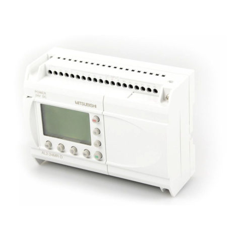
Figure 1.1 – Tap Position Indicator and Controller PI
2. Basic Operation Philosophy
In general, on-load tap changers (OLTC) are used in power transformers with the
objective of allowing the regulation of secondary voltage to the loads without
interruption in electrical energy supply. By changing the OLTC position it is
possible to raise or lower the transformer secondary voltage. The total number of
positions in the tap changer can vary according to the application needs.

Technical Manual PI – V1.2 MA-005 Rev. 1 16/01/2004 Page I - 3
2.1Manual/Automatic Command Modes
Regarding to the type of raise/lower commands for the OLTCs, there are two
possibilities: Manual Command or Automatic Command. By selecting the Manual
Command mode, the tap changes occur only when requested by the operator,
while the Automatic Mode enables the raise/lower tap commands sent by an
Automatic Voltage Regulator Relay (relay 90).
2.2 Local/Remote Command Modes
Regarding to the local from where can be performed the selections
Automatic/Manual and the commands raise/lower tap, there are three possibilities:
a) Local Command, by the PI front keypad;
b) Remote Command, by external dry contacts connected to the PI;
c) Remote Command, by the serial communication RS485, from a supervisor
system.
If the Local Command is selected, both of the remote command modes remain
blocked (in case of serial communication, only the information acquisition is
possible). If the Remote command were selected, the system operation by the front
keyboard remains blocked, liberating both of the remote command modes. In
general, only one of the both remote command options is used, because one
eliminates other’s necessity. It is possible, however, to have both remote modes
operating simultaneously.

Technical Manual PI – V1.2 MA-005 Rev. 1 16/01/2004 Page II - 1
Section II – Operation
Index of Subjects
Chapter Title Page
3 Local Operation of the PI II – 2
3.1 Primary indications in the display II – 2
3.2 Local/Remote and Manual/Automatic Selections II – 3
3.3 Raise/Lower Tap manual command II – 4
3.4 Error Conditions Alarms II – 5
3.4.1 Tap Position Reading Error (E08) II – 5
3.5 System Operation during error conditions II – 7
3.5.1 E08 - Tap Position Reading Error II – 7
Index of Pictures
Picture Title Page
3.1 Indication of the tap changer current position II - 3
3.2 Indication during a change of position in progress II - 3
3.3 Indication during an error condition occurrence II - 4

Technical Manual PI – V1.2 MA-005 Rev. 1 16/01/2004 Page II - 2
3. Local Operation of PI
The local operation of the PI is done by its front panel, using the P, ↑and ↓keys,
with the support of the equipment display.
3.1Primary indications in the display
During the system autonomous operation, without the operator intervention by the
front keys, the PI display can accomplish one of the following indications:
a) Current position of the on-load tap changer associated to it. The display
indicates permanently this information, which can be shown by simple
numeric, bilateral numeric or alphanumeric formats (for example: 1...17, -
8...0...+8 or 8L...N...8R respectively). See picture 3.1;
Picture 3.1 – Indication of the tap changer current position
b) Intermittent indication of the tap changer current position and indication of
the symbols ↑↑↑or ↓↓↓, if a tap change is in progress to raise or lower
tap respectively. See picture 3.2;
MESTRE
COMAND.
INDIVIDUAL
AUTO/REM.
MANUAL
TECH
+13
MESTRE
COMAND.
INDIVIDUAL
AUTO/REM.
MANUAL
TECH
+13 MESTRE
COMAND.
INDIVIDUAL
AUTO/REM.
MANUAL
TECH
^^^

Technical Manual PI – V1.2 MA-005 Rev. 1 16/01/2004 Page II - 3
Picture 3.2 – Indication during a change of a position in progress
c) Intermittent indication of the tap changer current position and an error code.
The description of the possible error conditions and the associated codes
can be verified in the item 3.6. See picture 3.3.
Picture 3.3 – Indication during an error condition occurrence
During the operator interventions by the front keyboard, the indications in the
display are the following described in the item 3.2.
3.2Local/Remote and Manual/Automatic Selections
The Local/Remote and Manual/Automatic selections can be operated in local
manner, by the SPS front keyboard, as described below.
MESTRE
COMAND.
INDIVIDUAL
AUTO/REM.
MANUAL
TECH
+13 MESTRE
COMAND.
INDIVIDUAL
AUTO/REM.
MANUAL
TECH
E08

Technical Manual PI – V1.2 MA-005 Rev. 1 16/01/2004 Page II - 4
Procedure Effect Preview
Press Key P for a
moment.
It is accessed the first programming
menu, with the Local/Remote selection.
The current status of this selection is
displayed respectively by LOC or REM
codes.
Press ↑or ↓keys for a
moment.
The selection is changed from Local to
Remote or vice versa.
Procedure Effect Preview
If during the previous step the Remote
mode was selected, the PI exists the
programming menu, returning to the
condition described in 3.1
Press Key P for a
moment If during the previous step the Local
mode was selected, it is accessed the
second programming menu, with
Manual/Automatic selection. The current
status of this selection is displayed
respectively by MAN or AUT codes.
Press ↑or ↓keys for a
moment
The selection is changed from Manual to
Automatic or vice versa.
Press Key P for a
moment
The PI exits the programming menu,
returning to the condition described in 3.1
or
or
MESTRE
COMAND.
INDIVIDUAL
AUTO/REM.
MANUAL
TECH
Loc
MESTRE
COMAND.
INDIVIDUAL
AUTO/REM.
MANUAL
TECH
REM
MESTRE
COMAND.
INDIVIDUAL
AUTO/REM.
MANUAL
TECH
Loc
MESTRE
COMAND.
INDIVIDUAL
AUTO/REM.
MANUAL
TECH
REM
MESTRE
COMAND.
INDIVIDUAL
AUTO/REM.
MANUAL
TECH
+13
MESTRE
COMAND.
INDIVIDUAL
AUTO/REM.
MANUAL
TECH
MAN
MESTRE
COMAND.
INDIVIDUAL
AUTO/REM.
MANUAL
TECH
AUT
MESTRE
COMAND.
INDIVIDUAL
AUTO/REM.
MANUAL
TECH
MAN
MESTRE
COMAND.
INDIVIDUAL
AUTO/REM.
MANUAL
TECH
AUT
MESTRE
COMAND.
INDIVIDUAL
AUTO/REM.
MANUAL
TECH
+13

Technical Manual PI – V1.2 MA-005 Rev. 1 16/01/2004 Page II - 5
3.3Raise/Lower Tap manual command
The manual command to Raise and Low the position of the on-load tap changer
can be operated in local manner, using the ↑and ↓keys of the PI front, as
described below. These commands will only be followed if a previous selection of
the Local and Manual command modes is done.
Procedure Effect Preview
If the Remote mode were previously
selected, the display will show the REM
message during 1 second, indicating that
the command will not be followed,
because the PI is selected in this mode.
Press ↑or ↓keys for a
moment If the Local and Manual command modes
are selected, the corresponding
command will be sent to the on-load tap
changer, and it will be displayed that the
tap change is in progress by the
periodical indication of the ↑↑↑ or ↓↓↓
symbols on the display.
3.4Error Conditions Alarms
The alarm conditions of the PI are signalized in the front display by the error codes
listed below, besides that it allows its remote signaling by output contacts, as
described in sub-chapter 5.6.
All the error indications are automatically restarted, that is, the indication displayed
disappears when the error condition is eliminated, the same occurs with the
corresponding signaling contact, which returns to its repose condition.
or
MESTRE
COMAND.
INDIVIDUAL
AUTO/REM.
MANUAL
TECH
Rem
MESTRE
COMAND.
INDIVIDUAL
AUTO/REM.
MANUAL
TECH
^^^
MESTRE
COMAND.
INDIVIDUAL
AUTO/REM.
MANUAL
TECH

Technical Manual PI – V1.2 MA-005 Rev. 1 16/01/2004 Page II - 6
Code Error Condition
E08 Tap position reading error
3.4.1 Tap Position Reading Error (E08)
It is caused by a reading fail of the current tap position of the load tap changer. It is
detected by the following reading consistency verifications. For each one of these
verifications is applied an error cause code, that is stored for posterior verification
by the maintenance staff.
a) Internal Error in the communication between the tap reading microcontroller
and the principal microcontroller. This reading error cause is stored as the
"C1" code,
b) Unstable tap position reading, in other words, floating much more fast than
what would be possible for the normal operation of the load tap changer.
This reading error cause is stored as the "C2" code,
c) Inconsistency in the tap position calculated from the several resistance
measurements accomplished in the potentiometric transmitter of the tap
changer. This reading error cause is stored as the "C3" code.
Without putting away another possibilities that can be verified, the possible causes
for this error are:
•Excessive electromagnetic interference in the measurement cables of the
potentiometric position transmitter, due to the usage of non-shielded cables (C2
cause);
•Excessive electromagnetic interference due to the lack of grounding of the
measurement cables shield of the potentiometric position transmitter (C2
cause);
•Excessive Electromagnetic interference due to the grounding of the
measurement cables shield of the potentiometric position transmitter in more

Technical Manual PI – V1.2 MA-005 Rev. 1 16/01/2004 Page II - 7
than one point, enabling the current circulation by the shield due to the ground
potential differences (C2 cause);
•Poor contact in the cursor of the potentiometric position transmitter or in the
connection cables from this one to the PI (C3 cause);
•Connection cables from the potentiometric position transmitter to the PI with
resistance superior to 8Ωper wire - very reduced size due to the roaming
distance (C3 cause);
•Connection cables from the potentiometric position transmitter to the PI with
different sizes or with different lengths in each wire (C3 cause);
•Defect in the PI tap measurement circuit (C1cause).
3.5 System Operation during errors presence
An ideal proceeding during any error occurrence is, naturally, detecting and
correcting its cause before continue the operation of the system.
However, when this proceeding is not possible to be done, or when there is no time
left to the problem correction, due to the prompt necessity of the system operation,
some emergency proceedings can be used, as suggested bellow. It must be taken
all cares related to the indicated Special Cautions, to prevent conditions with risk of
transformer trip by the protection operation or even with risk to the transformer
integrity.
3.5.1 E08 – Tap Reading Error
Error condition
and its Local •E08 (tap reading error)
Contingency
Procedure
•The transformer that contains error can only be operated from the on-load
tap changer, as it is not possible to know by the PI what is the real tap position
of the tap changer.
Special
Cautions •Use the mechanical position indicator in the OLTC motor cabinet for
checking of the raise/lower commands performed.

Technical Manual PI – V1.2 MA-005 Rev. 1 16/01/2004 Page III - 1
Section III – Project and Installation
Index of Subjects
Chapter Title Page
4 Topology for PI application III – 3
5 Inputs and Outputs III – 5
5.1 Auxiliary power and ground III – 5
5.2 Tap changer position measurement III – 5
5.2.1 Connection cables for tap measurement III – 5
5.2.2 Requirements for the tap position transmitter III – 7
5.3 Analog output of tap changer position III – 8
5.4 Raise/Lower Tap output Contacts III – 9
5.5 Contact inputs for Remote Programming/Command III – 10
5.5.1 Local/Remote programming input III – 11
5.5.2 Manual/Automatic programming input III – 11
5.5.3 Raise/Lower Tap command Inputs III – 12
5.6 Output Relays for Signaling III – 13
5.7 Serial communication RS485 III – 14
6 Connection diagrams III – 14
7 Mechanical Installation III – 15
Index of Pictures
Picture Title Page
4.1 Topology of PI application III – 3
4.2 PI front panel III – 4

Technical Manual PI – V1.2 MA-005 Rev. 1 16/01/2004 Page III - 2
Index of Pictures (continues)
5.1 Shield connection of the tap measurement cables III – 6
5.2 Resistors configuration of the potentiometric transmitter in
intermediary positions of the on-load tap changer III – 8
5.3.a Manual/Automatic remote programming using a single
programming contact III – 12
5.3.b Manual/Automatic remote programming using two programming
contacts III – 12
5.4 Contacts connection of Raise/Lower external commands of
Automatic and Manual operation devices III – 13
5.5 PI signaling contacts III – 13
6.1 PI connection diagram III – 14
7.1 PI outline dimensions III – 15

Technical Manual PI – V1.2 MA-005 Rev. 1 16/01/2004 Page III - 3
4. Topology for PI application
For each On-Load Tap Changer it is used a unity of the Position Indicator and
Controller PI. The serial communication RS485 ports of the PI allow the serial
communication of them with an external data acquisition system (supervisor
system). See figure 4.1.
Figure 4.1 – Topology of PI application
OLTC
TRANSFORMER 1
TAP
Measurement
Raise/Lower
Tap commands
...
Serial Communication
RS 485 for Supervisor
System
PI
...
PIPI TECH
6l
TECH
6l
TEC H
6l
TRANSFORMER 2 TRANSFORMER 3
OLTC OLTC
TAP
Measurement
TAP
Measurement
Raise/Lower
Tap commands
Raise/Lower
Tap commands
MESTRE
COMAND.
INDIVIDUAL
AUTO/REM.
MANUAL
TECH
6l
MESTRE
COMAND.
INDIVIDUAL
AUTO/REM.
MANUAL
TECH
6l
MESTRE
COMAND.
INDIVIDUAL
AUTO/REM.
MANUAL
TECH
6l

Technical Manual PI – V1.2 MA-005 Rev. 1 16/01/2004 Page III - 4
In the picture 4.2 it is shown the PI front panel, composed by:
1) Indicator LED for the command mode Manual selected (in Automatic mode this
LED turns off);
2) Indicator LED for the command mode Remote selected (in Local mode this LED
turns off);
3) P, ↑and ↓front keys, with the functions:
•Manual/Automatic and Local/Remote selections;
•Raise/Lower tap position manual commands;
•PI configuration.
4) Three-digit display for indicating:
•Current tap position;
•Position change in progress;
•Support to the Manual/Automatic and Local/Remote selections;
•Support to the PI configuration;
•Indication codes for error conditions.
Figure 4.2 – PI Front panel
1
23
4
MESTR
E
MANUA
AUTO
MASTER
MANUAL
AUTO
INDIV.
FOLLOWER
TECH
+13
MESTRE
COMAND.
INDIVIDUAL
AUTO/REM.
MANUAL
TECH
+13

Technical Manual PI – V1.2 MA-005 Rev. 1 16/01/2004 Page III - 5
5. Inputs and Outputs
The following described Inputs and Outputs are available in the PI. A general vision
of all the inputs and outputs can be observed in chapter 6.
5.1Auxiliary power and Ground
The PI is capable to operate with auxiliary power in the range from 85 to 265V, in
AC or DC, 50 or 60Hz, with consumption lower than 6W. It must be effected the
connection of the terminal corresponding to the ground.
♦Power input: terminals 16 and 17;
♦Ground: terminal 15.
5.2Tap changer position measurement
The PI performs the on-load tap changer position measurement in order to make
this information available to the user. This measurement is accomplished by a PI
input, specific for connecting a potentiometric position transmitter of the on-load tap
changer.
The PI is provided by an internal microcontroller exclusively dedicated to the
necessary calculation for the tap position measurement, verification of its
consistency and compensation of the measurement cables resistance.
♦Tap measurement input: terminals 12, 13 and 14 (cursor, start and end,
respectively).
5.2.1 Connection cables for tap measurement
The connection of the pontentiometric position transmitter of the on-load tap
changer to the PI is accomplished by three wires: the cursor, the start and the end
of the potentiometric transmitter. The three wires must have the same length and
size.
For this connection, it must be used shielded cable in the whole course, from the
tap changer cabinet to the PI, with the shield grounded in a single point.

Technical Manual PI – V1.2 MA-005 Rev. 1 16/01/2004 Page III - 6
If it is not used a single shielded cable for the whole course, due to intermediary
terminal blocks connection, the shield continuity must be ensured through the
interconnection of the shield extremes. See picture 5.1. The unshielded stretch
cable, due to seam, must be as short as possible.
Figure 5.1 – Shield connection of tap measurement cable
The PI performs the automatic compensation of the connection cables resistance
from the pontentiometric transmitter to the PI, and to such performance, the three
wires must have the same length and size, and the maximum acceptable
resistance for each wire is 8Ω. Due to this maximum resistance and the size of the
cables used, it can be obtained the maximum permitted length for them.
Considering cables with typical resistance of 13.3 Ω/km, 7.98 Ω/km and 4.95 Ω/km
for the sizes 1,5mm2, 2,5mm2and 4mm2respectively (non-tinned cables), the
maximum lengths are shown in the following table.

Technical Manual PI – V1.2 MA-005 Rev. 1 16/01/2004 Page III - 7
Cables Size Typical Resistance Maximum Length
0.5 mm239.0 Ω/km 200 m
0.75 mm226.0 Ω/km 300 m
1 mm219.5 Ω/km 400 m
1.5 mm213.3 Ω/km 600 m
2.5 mm27.98 Ω/km 1000 m
4 mm2 4.95 Ω/km 1600 m
5.2.2 Requirements for the tap position transmitter
The on-load tap changer position transmitter must be of the pontentiometric type,
with its resistance changing from zero to the maximum value for the start and finish
tap changer positions respectively.
In case of tap changers with "intermediary" positions, namely, transition positions
that have the same voltage of other adjacent positions, as shown in the following
table, the resistors of the potentiometric crown relative to these positions must be
removed and/or short circuited, as shown in the example of the picture 5.2. All the
intermediary positions (in the example, 6A, 6 and 6B) will be indicated as tap "6",
because they have the same voltage.
Tap Position Voltage (V) Current(A) Resistance Cursor/Initial Position
(example for 10Ω
ΩΩ
Ω/step)
1 12420 3220,6 0
2 12696 3150,6 10
3 12972 3083,6 20
4 13248 3019,3 30
5 13524 2957,7 40
6A 50
650
6B
13800 2898,6
50
7 14076 2841,7 60
8 14352 2787,1 70
9 14628 2734,5 80
10 14904 2683,8 90
11 15180 2635,0 100

Technical Manual PI – V1.2 MA-005 Rev. 1 16/01/2004 Page III - 8
Figure 5.2 – Configuration of potentiometric transmitter resistors at tap changer
intermediate positions
The SPS accepts resistance by potentiometric transmitter step (the value of each
individual transmitter shown in the picture 5.2) in the range from 4,7 to 20Ω, and
the total resistance of the transmitter from 9,4 to 1000Ω. The mobile contact
(cursor) of the potentiometric transmitter can be "close before open" or "open
before close" type, indifferently.
5.3Analog output of tap changer position
The PI has an analog output in current loop for remote indication of the tap
changer position. The current output value range can be selected using the
programming performed in the front of the PI as shown in one of the following
options. The output maximum voltage is 12V, what accepts that be connected the
maximum loads indicated by the side of each option:
INITIAL POSITION
Table of contents
