4
SECTION 1 – SAFETY PRECAUTIONS – READ BEFORE USING
1-1 Additional Safety Warnings for
Installation, Operation and Maintenance
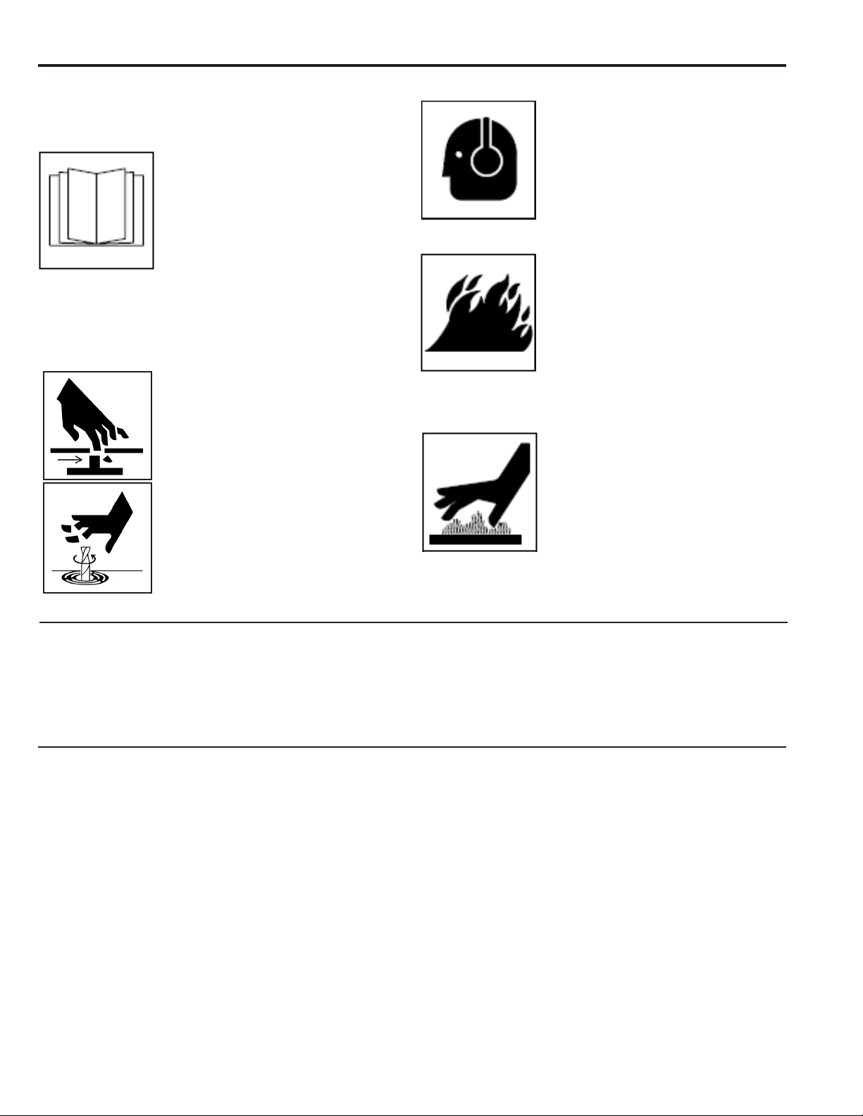
READ INSTRUCTIONS
• Read and follow all labels and the
Owner’s Manual carefully before
installing, operating, or servicing the
unit. Read the safety information at
the beginning of the manual and each
section.
• Use only genuine replacement parts from the manufacturer.
• Perform maintenance and service according to the Owner’s
Manual, industry standards and national, state/provincial and
local codes.
FIRE OR EXPLOSION hazard
• Do not install or place unit on, over or
near combustible surfaces.
• Do not install unit near ammables.
• Do not overload building wiring – be
sure power supply system is properly
sized, rated and protected to handle
this unit.
HOT PARTS can burn
• Do not touch hot parts barehanded.
• Allow cooling period before working
on equipment.
• To handle hot parts, use proper tools
and/or wear heavy, insulated welding
gloves and clothing to prevent burns.
NOISE can damage hearing
• Noise from some processes or
equipment can damage hearing.
• Wear approved ear protection if noise
level is high.
1-2 California Proposition 65 Warnings
Welding or cutting equipment produces fumes or gases which
contain chemicals known to the State of California to cause birth
defects and in some cases, cancer. (California Health & Safety
Code Section 25249.5 et seq.)
This product contains chemicals, including lead, known to the
State of California to cause cancer, and birth defects or other
reproductive harm. Wash hands after use.
1-3 Principal Safety Standards
Safety in Welding, Cutting, and Allied Processes, ANSI Standard
Z49.1, is available as a free download from the American Welding
Society at www.aws.org or purchased from Global Engineering
Documents (phone: 1-877-413-5184, website:
www.global.ihs.com).
National Electrical Code, NFPA Standard 70, from National Fire
Protection Association, Quincy, MA 02269 (phone: 1-800-344-
3555, website: www.nfpa.org and www.sparky.org).
Safety in Welding, Cutting, and Allied Processes, CSA Standard
W117.2, from Canadian Standards Association, Standards Sales,
5060 Spectrum Way, Suite 100, Ontario, Canada L4W 5NS
(phone: 1-800-463-6727, website: www.csa-international.org).
Safe Practice For Occupational And Educational Eye And Face
Protection, ANSI Standard Z87.1, from American National
Standards Institute, 25 West 43rd Street, New York, NY 10036
(phone: 212-642-4900, website: www.ansi.org).
OSHA, Occupational Safety and Health Standards for General
Industry, Title 29, Code of Federal Regulations (CFR), Part 1910,
Subpart Q, and Part 1926, Subpart J, from U.S. Government
Printing Ofce, Superintendent of Documents, P.O. Box 371954,
Pittsburg, PA 15250-7954 (phone: 1-866-512-1800) (there are
10 OSHA Regional Ofces – phone for Region 5, Chicago, is 312-
353-2220, website: www.osha.gov).
Applications Manual for the Revised NIOSH Lifting Equation, The
National Institute for Occupational Safety and Health (NIOSH),
1600 Clifton Road, Atlanta, GA 30333 (phone: 1-800-232-4636,
website: www.cdc.gov/NIOSH).
MOVING PARTS can injure
• Keep away from moving parts such as
fans and blades.
• Keep all doors, panels, covers and
guards closed and securely in place.
• Have only qualied persons remove
doors, panels, covers or guards for
maintenance and troubleshooting as
necessary.
• Reinstall doors, panels, covers or
guards when maintenance is nished
and before reconnecting input power.
• Keep away from pinch points.