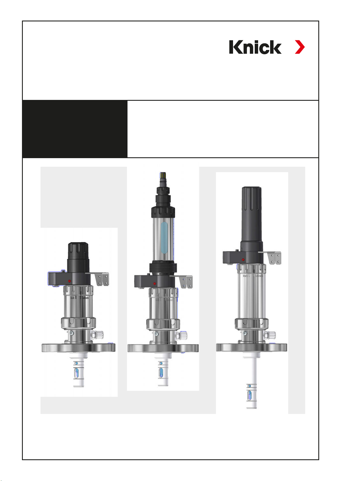
Knick SensoGate WA 132 Series User manual

The Art of Measuring.
Information: www.knick-international.com
SensoGate WA 132
Retractable Fitting with PTFE Process Adaptation
User Manual

Table of Contents
SensoGate WA 132
Safety Instructions ........................................................................................................................... 3
Intended Use..................................................................................................................................... 5
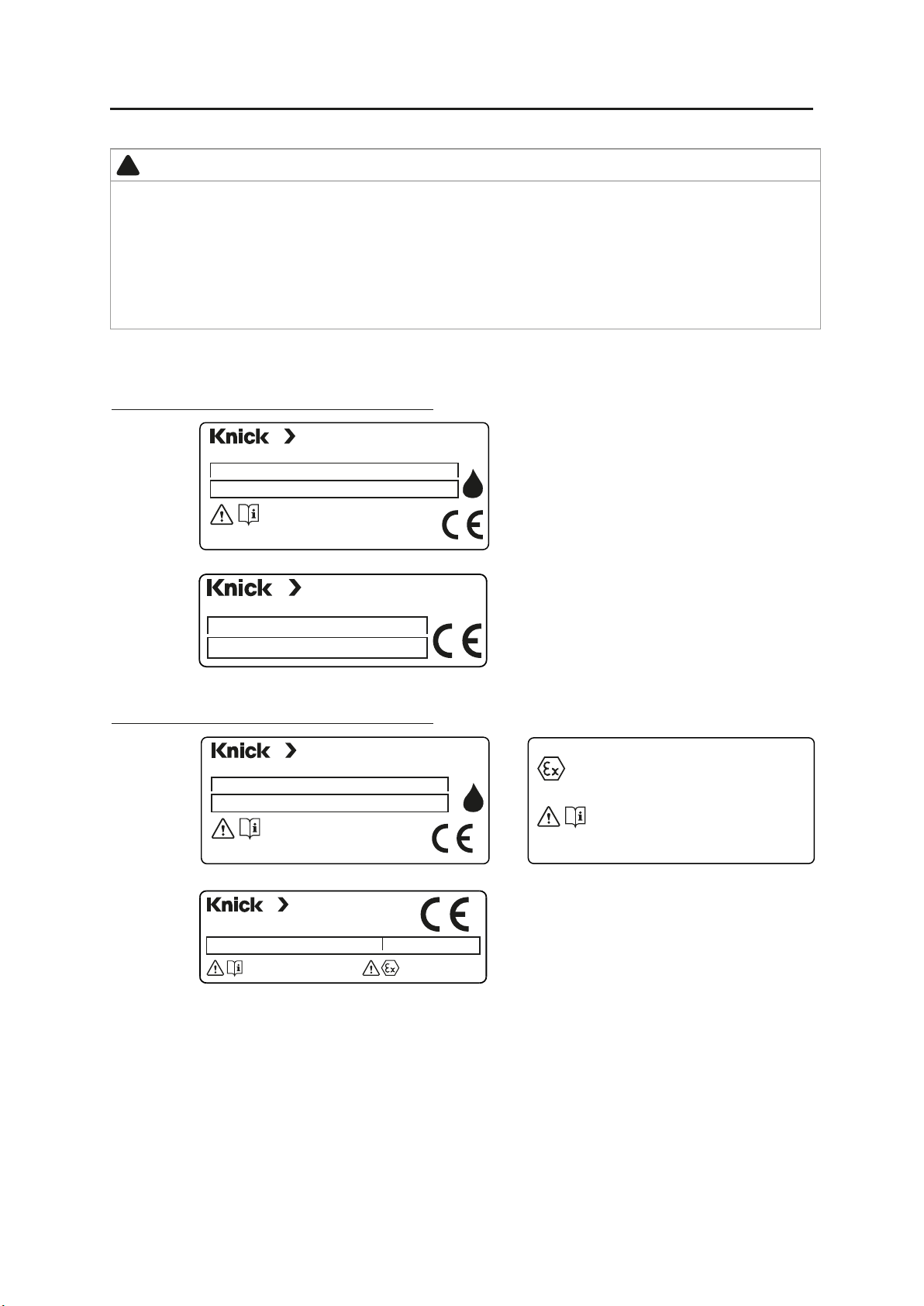
Symbols and Markings.................................................................................................................................................................. 5
Rating Plates ..................................................................................................................................................................................... 6
Package Contents ........................................................................................................................................................................... 6
SensoGate WA 132 Product Coding................................................................................................7
Function Description........................................................................................................................ 8
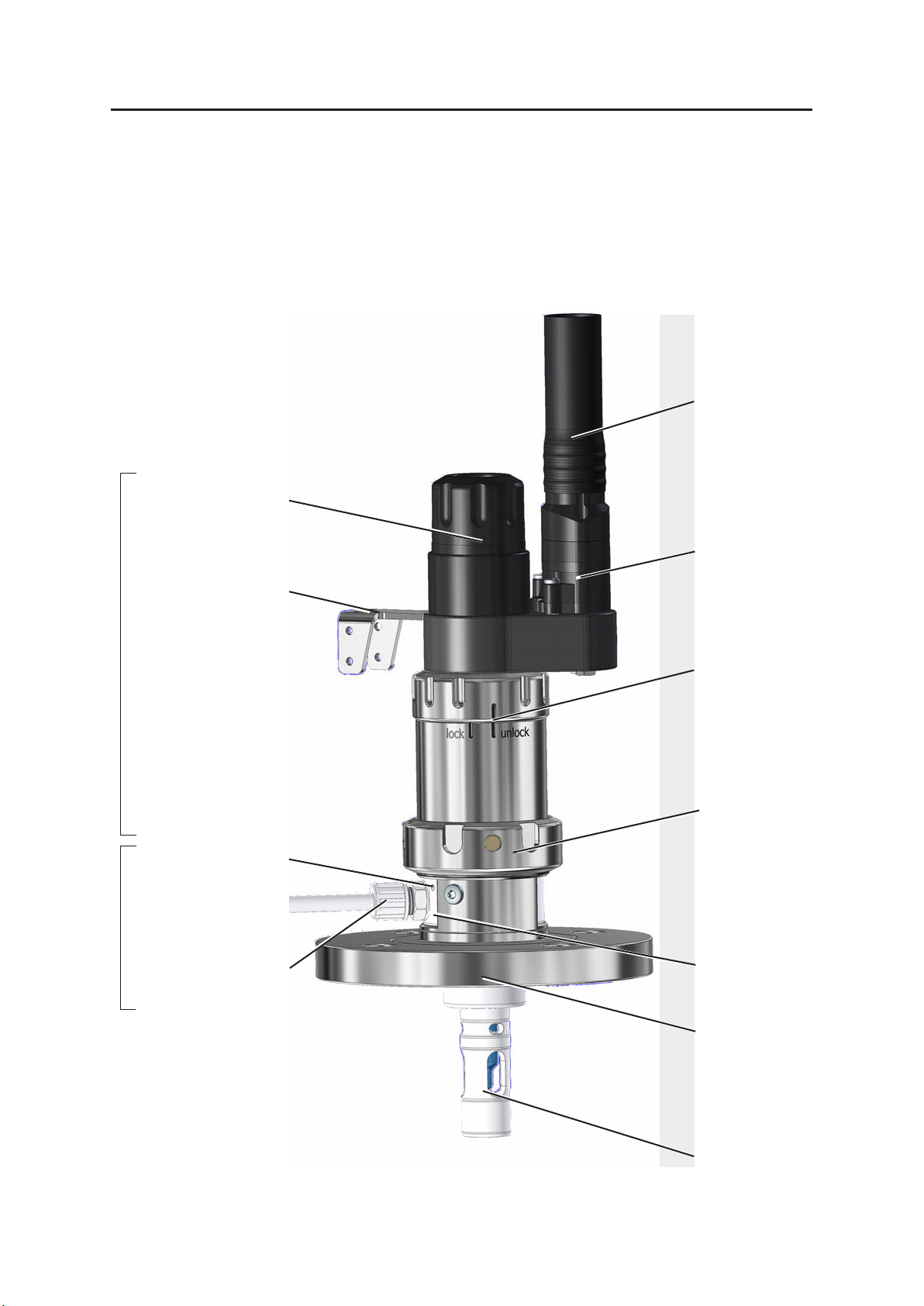
Overview of Retractable Fitting......................................................................................................9
Modular Design: Drive Unit, Immersion Tube, Process Adaptation...........................................................................10
SensoLock .......................................................................................................................................11
Media Connection ..........................................................................................................................12
Installing the Media Connection.............................................................................................................................................12
SERVICE Position ............................................................................................................................13
PROCESS Position...........................................................................................................................14
Installing and Removing a Sensor ................................................................................................15
Sensors with Solid Electrolyte.......................................................................................................16
Short Immersion Depth..............................................................................................................................................................16
Installing the Sensor ................................................................................................................................................................16
Removing the Sensor..............................................................................................................................................................18
Long Immersion Depth...............................................................................................................................................................19
Installing the Sensor ................................................................................................................................................................19
Removing the Sensor..............................................................................................................................................................21
Sensors with Liquid Electrolyte.....................................................................................................23
Installing the Sensor ................................................................................................................................................................23
Removing the Sensor..............................................................................................................................................................24
Drive Unit ........................................................................................................................................25
Removing the Drive Unit .......................................................................................................................................................25
Installing the Drive Unit .........................................................................................................................................................26
Immersion Tube ..............................................................................................................................27
Replacing the Immersion Tube............................................................................................................................................27
Removing the Immersion Tube...........................................................................................................................................28
Installing the Immersion Tube .............................................................................................................................................29
Calibration Chamber......................................................................................................................30
Removing the Calibration Chamber..................................................................................................................................30
Installing the Calibration Chamber....................................................................................................................................31
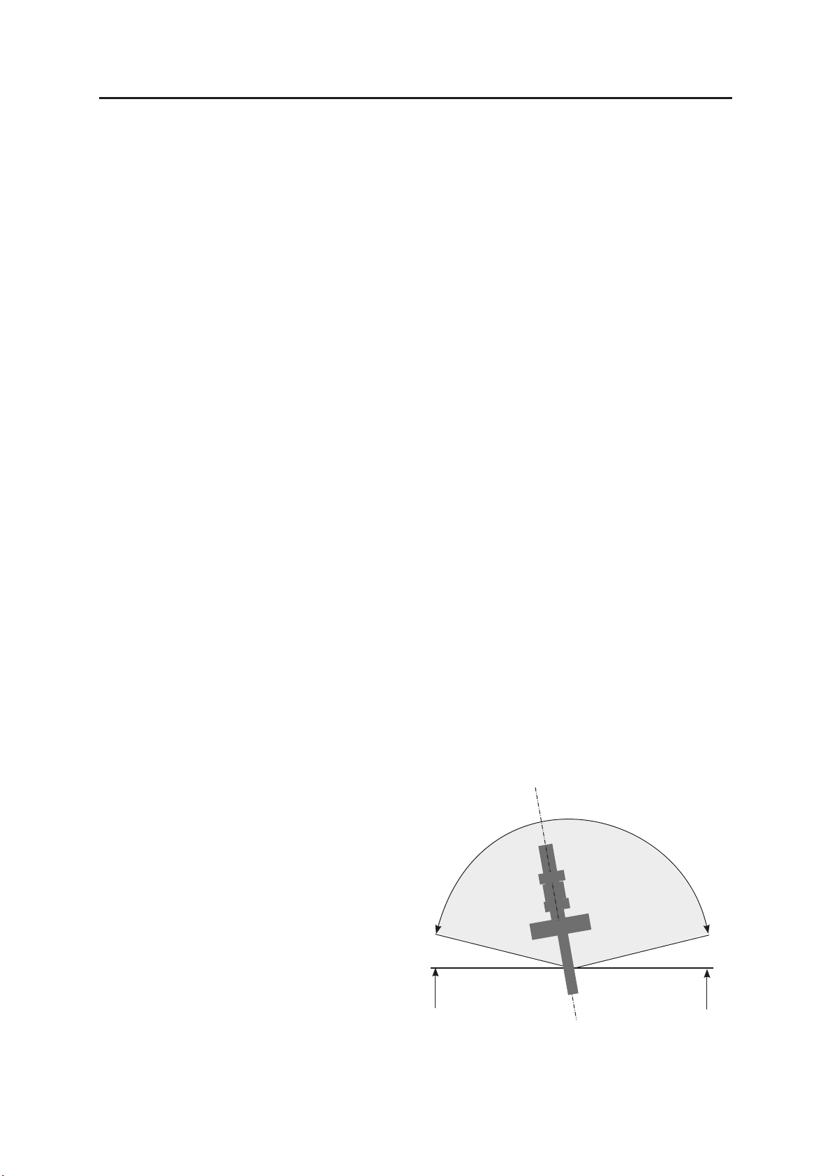
Installation Dimensions.................................................................................................................32
Specifications..................................................................................................................................36
Maintenance ...................................................................................................................................37
Maintenance Intervals.................................................................................................................................................................37
Servicing the Immersion Tube .................................................................................................................................................37
Servicing the Drive Unit .............................................................................................................................................................38
Lubricants, O-Rings ......................................................................................................................................................................38
Sealing Kits for Maintenance and Servicing .......................................................................................................................39
Accessories / Spare Parts ...............................................................................................................40
Declaration of Contamination.......................................................................................................42
Index................................................................................................................................................43
2

Registered Trademarks
The following trademarks are used in this manual without further marking:
SensoGate®, SensoLock®, Unical®, Uniclean®, Protos®
are registered trademarks of Knick Elektronische Messgeräte GmbH & Co. KG, Germany
Return of Products/Return Form
Please contact our Service Team before returning a defective device. Ship the cleaned device to
the address you have been given. If the device has been in contact with process fluids, it must be
decontaminated/disinfected before shipment. In that case, please attach a corresponding return
form (see page 43), for the health and safety of our service personnel.
Safety Instructions
SensoGate WA 132
Process-Related Risks
Knick Elektronische Messgeräte GmbH & Co. KG assumes no liability for damages
caused by process-related risks known to the operator, which would in fact not permit
the use of the retractable fitting.
For your own safety, be sure to observe the following precautions:
Work on the retractable fitting shall only be performed by personnel authorized by the
operating company and specially trained for handling and operating the retractable
fitting.
Be sure to take account of the influences of humidity, ambient temperature, chemicals,
and corrosion on the safe operation of the retractable fitting.
4 to 7 bar
Rinsing water: max. 7 bar
Made in Germany
-10 to 70 °C
Retractable probe / Drive unit
No self-heating For temp specs see manual
14163 Berlin 66
IP
SensoGate®
SensoGate®
4 to 7 bar
max. 7 bar
Tamb -10 to 70 °C
Drive unit
0044
Made in Germany
Made in Germany
For Ex specs see drive unit
KEMA 07 ATEX 0065
SensoGate®
SensoGate®
Type
Type
No.
No.
Insertion fitting
Insertion fitting
WA130-N*, WA130-X*,
WA132-N*, WA132-X*
Prozess
0044
3
The SensoGate WA 132 retractable fitting has been developed and manufactured in compli-
ance with the applicable European guidelines and standards. Compliance with the European
Harmonized Standards for use in hazardous locations is confirmed by the EU Type Examination
ean direCertificate. Compliance with the Europ ctives and standards is confirmed by the
nformity an E markiEUDeclaration of Co d the C ng.

Safety Instructions
SensoGate WA 132
Operation in Explosive Atmospheres
The SensoGate WA132-X is certified for operation in explosive atmospheres.
• EU-Type Examination Certificate KEMA04ATEX4035X
Exceeding the standard atmospheric conditions within the manufacturer’s specifications, such as ambient tem-
perature, process pressure and temperature, does not impair the durability of the retractable fittings.
Related certificates are included in the product’s scope of delivery and are available at www.knick.de in the cur-
rent version.
Observe all applicable local and national codes and standards for the installation of equipment in explosive at-
mospheres. For further guidance, consult the following:
• IEC60079-14
• EU directives 2014/34/EU and 1999/92/EC(ATEX)
Possible Ignition Hazards During Installation and Maintenance
To avoid mechanically generated sparks, handle the SensoGate WA132-X with care and apply suitable measures,
e.g., use covers and pads.
The metallic parts of the SensoGate WA132-X must be connected to the plant’s equipotential bonding using the
metallic process connection and the grounding connection provided for that purpose.
When components are replaced with genuine Knick spare parts made of other materials (e.g. O-rings), the infor-
mation given on the nameplate may deviate from the actual version of the SensoGate WA132-X. The operating
company must assess and document this deviation.
Electrostatic charging
The drive unit of specific versions of the SensoGate WA132-X contains housing components made of non-con-
ductive plastic. Due to their surface, the housing components may build up an electrostatic charge. To prevent
this charge from becoming an effective ignition source in Zone0, ensure that the following conditions are met:
• Highly efficient charge generating mechanisms are excluded
• Non-metallic components are cleaned with a moist cloth only
Mechanically generated sparks
Single impacts on metal parts or collisions between metal parts of the SensoGate WA132-X are not a potential
ignition source only if the following conditions are met:
• Possible impact velocity is less than 1 m/s
• Possible impact energy is less than 500 J
If these conditions cannot be ensured, the operating company must reassess single impacts on metal parts or
collisions between metal parts as potential sources of ignition. The operating company must implement suitable
risk minimization measures, e.g., by ensuring a non-explosive atmosphere.
Possible Ignition Hazards During Operation
When using non-water-based cleaning, rinsing, or calibration media with a low conductivity of less than 1nS/m,
electrostatic charging of internal, conductive components may occur. The operating company must assess the
associated risks and implement appropriate measures.
The sensors that are used must be approved for operation in hazardous locations. Further information can be
found in the sensor documentation.
Electrostatic charging
The wetted components of the SensoGate WA132-X process unit are made of non-conductive PTFE plastic. The
components can build up an electrostatic charge. To prevent this charge from becoming an effective ignition
source, ensure that the following conditions are met:
• Efficient charge generating mechanisms are excluded
• Process media are grounded and have a minimum conductivity of 10 nS/cm
If these conditions cannot be ensured, operation in Zone0 and Zone1 is not permitted.
4

5
Intended Use
SensoGate WA 132
Intended Use
The SensoGate WA 132 is a pneumatically operated retractable fitting. It allows sensors to be
immersed in and retracted from liquid media, e.g., for process analytics.
The SensoGate WA 132 retractable fitting allows:
•immersing and retracting the sensor under process pressure (retractable fitting)
•calibrating or adjusting the measuring system under process conditions
(pressure and temperature)
• cleaning the sensor in the running process (optional)
• replacing the sensor in the running process (in Service position)
•variable process adaptation by the customer
The retractable fitting is suitable for sensors with a sensor diameter of 12 mm and a PG 13.5
thread. The following sensors can be installed:
• sensor with solid electrolyte, 225 mm long
•sensor with liquid electrolyte, 250 mm long
Safe Use
If you are not sure whether the retractable fitting can be safely used for your
intended application, always contact Knick!
To ensure safe use of the equipment, you must observe the temperature and
pressure ranges given in the Specifications of this user manual.
Symbols and Markings
Symbol Meaning
Compressed air: 4 to 7 bar
Rinsing water: max. 7 bar
Made in Germany
-10 to 70 °C
Retractable probe / Drive unit
KEMA 07ATEX 0065
No self-heating For temp specs see manual
14163 Berlin 66
IP
SensoGate®
SensoGate®
4 to 7 bar
max. 7 bar
Tamb -10 to 70 °C
Drive unit
0044
Made in Germany
Made in Germany
For Ex specs see drive unit
KEMA 07 ATEX 0065
SensoGate®
SensoGate®
Type
Type
No.
No.
Insertion fitting
Insertion fitting
Schilder
WA130-N*, WA130-X*,
WA132-N*, WA132-X*
Prozess
0044
CE marking with number of the notified body for the EU Type Examination
Certificate
4 to 7 bar
Rinsing water: max. 7 bar
Made in Germany
-10 to 70 °C
Retractable probe / Drive unit
No self-heating For temp specs see manual
14163 Berlin 66
IP
SensoGate®
SensoGate®
4 to 7 bar
max. 7 bar
Tamb -10 to 70 °C
Drive unit
0044
Made in Germany
Made in Germany
For Ex specs see drive unit
KEMA 07 ATEX 0065
SensoGate®
SensoGate®
Type
Type
No.
No.
Insertion fitting
Insertion fitting
WA130-N*, WA130-X*,
WA132-N*, WA132-X*
Prozess
0044
ATEX marking for the operation of equipment in hazardous locations with device
classification (see page 36)
4 to 7 bar
Rinsing water: max. 7 bar
Made in Germany
Drive unit
No self-heating For temp specs see manual
14163 Berlin 66
IP
SensoGate®
SensoGate®
4 to 7 bar
max. 7 bar
mb -10 to 70 °C
Drive unit
0044
Made in Germany
Made in Germany
For Ex specs see drive unit
KEMA 07 ATEX 0065
SensoGate®
SensoGate®
Type
Type
No.
No.
Insertion fitting
Insertion fitting
WA130-N*, WA130-X*,
WA132-N*, WA132-X*
Prozess
0044
Do not open the device! Read this user manual, observe the Specifications, and
follow the safety instructions.
4 to 7 bar
Rinsing water: max. 7 bar
Made in Germany
unit
No self-heating For temp specs see manual
14163 Berlin 66
IP
SensoGate®
SensoGate®
4 to 7 bar
max. 7 bar
to 70 °C
0044
Made in Germany
Made in Germany
For Ex specs see drive unit
KEMA 07 ATEX 0065
SensoGate®
SensoGate®
Type
Type
No.
No.
Insertion fitting
Insertion fitting
WA130-N*, WA130-X*,
WA132-N*, WA132-X*
Prozess
0044
Ingress protection of the housing against dust and humidity
Outlet symbol
Tamb Ambient temperature
Table of contents
Other Knick Industrial Equipment manuals

Knick
Knick ProLine P16800 User manual

Knick
Knick ARD50EL User manual

Knick
Knick Ceramat WA160 User manual

Knick
Knick WA111 User manual

Knick
Knick SensoGate WA131 User manual

Knick
Knick Ceramat WA 154 User manual

Knick
Knick ARD 250 User manual

Knick
Knick Ceramat WA 153 User manual

Knick
Knick SensoGate WA131MH User manual