TREND IQ251 Instruction Manual

RGB ELEKTRONIKA AGACIAK CIACIEK
SPÓŁKA JAWNA
Jana Dlugosza 2-6 Street
51-162 Wrocław
Poland
biuro@rgbelektronika.pl
+48 71 325 15 05
www.rgbautomatyka.pl
www.rgbelektronika.pl
DATASHEET
www.rgbautomatyka.pl
www.rgbelektronika.pl
OTHER SYMBOLS:
IQ251
TREND

YOUR
PARTNER IN
MAINTENANCE
At our premises in Wrocław, we have a fully equipped servicing facility. Here we perform all the repair
works and test each later sold unit. Our trained employees, equipped with a wide variety of tools and
having several testing stands at their disposal, are a guarantee of the highest quality service.
OUR SERVICES
ENCODERS
SERVO
DRIVERS
LINEAR
ENCODERS
SERVO AMPLIFIERS
CNC
MACHINES
MOTORS
POWER
SUPPLIERS
OPERATOR
PANELS
CNC
CONTROLS
INDUSTRIAL
COMPUTERS
PLC
SYSTEMS
Repair this product with RGB ELEKTRONIKA ORDER A DIAGNOSIS ∠
Buy this product at RGB AUTOMATYKA BUY ∠

1
IQ251 Controller Data Sheet TA102315 Issue 4, 8/10/08
Data Sheet
IQ251
Controller
IQ251 Controller
Description
The IQ251 is a large capacity controller designed for the control of
all types of building equipment. It can provide up to 128 I/O points
by connecting 8 I/O modules in any combination. The range of I/O
modules comprises an 8 analogue plus 8 digital input module, an
8 analogue output module, and an 8 digital output module. IQ system
accessory modules may be connected to the input/output channels
to provide greater I/O flexibility. They enable the IQ251 to provide
sufficient capability for more complex strategies. It can operate
either as a stand alone device or as part of a Building Management
System. It provides access to all IQ controllers on a single or
multi-Lan system using a node controller integrated within the
IQ251. The IQ251 also provides the ability to connect any IQ system
supervisor or Engineering Tool to the network without the need for
a separate node controller.
Features
• 1 second cycle time.
• Access to entire network using local supervisor connection.
• Facility for mounting an additional node controller.
• High capacity DDC with PID control loops.
• Stand alone or integrated system operation.
• Up to 8 input/output modules for optimum configuration.
• Up to 96 logs.
• Up to 1000 values per log.
• Compatible with IQ151+ data files.
• Flexible I/O combinations
Physical
IQ251
RX
TX
175 mm (6.9”)
550 mm (21.7”)
440 mm (17.32”)
input power
I/O modules
LED
indicators
I/O modules
A D D R E S S
O N
R XT X
network
connector
network address/baud
supervisor
auxiliary node
knockout
RS232/modem
(for auxiliary node)
auxilary output
supply

2IQ251 Controller Data Sheet TA102315 Issue 4, 8/10/08
IQ251 Data Sheet
FUNCTIONALITY
The IQ Controller’s functionality can be divided into three sections, strategy, firmware, and hardware.
STRATEGY
The strategy processes inputs according to a set of instructions
and then outputs signals which can be used to control equipment.
Configuration: The IQ251 uses the standard IQ configuration
mode which enables configuration using the network, or using
the supervisor port. SET can be used to create a strategy data
file (.IQ2) which can then be downloaded to the controller and
subsequently uploaded for backup purposes if connected to the
controller directly or using the network, or using a modem.
Modules: The strategy consists of a number of individual
functional blocks known as configuration modules. These blocks
can be linked in various combinations to enable equipment to be
controlled in accordance with the building’s requirements. The
table lists the different types of configuration modules and the
number of each type available with IQ251.
Full details of the modules are given in the IQ Configuration Manual and Addendum. The IQ251 contains the normal IQ2 features
as described in IQ Configuration Manual Addendum: Engineers Journal (J), I/O Summary (i/o) Loader Issue (R(c),’c’ lower case),
Serial Number (R(s), ‘s’ lower case), Supply Frequency Option, Enhanced Logging, Module position, and Strategy Cleardown.
External Channels: Because the I/O modules may be fitted in
any combination in any of the 8 I/O slots, the channel numbers
must be carefully identified. In configuration mode the IQ251
identifies the external channel numbers corresponding to the
module number (in the case of sensors or digital inputs) or output
channel number (in the case of drivers).
The sensor and digital input modules, and the output channels
specified in the driver modules are related to the external channels
as shown in the table:
The external channels are referenced as follows:
[module position],[analogue(A) or digital(D) - input module only],[channel number]
e.g. BA1 position B, Analogue input, channel 1
BD1 position B, Digital input, channel 1
F1 position F, output channel 1
A7 position A, output channel 7
GD8 position G, Digital input, channel 8
A
B
C
D
E
F
G
H
module position
slennahCrosneSslennahCtupnIlatigiDslennahCrevirD
rebmuNrosneSlennahClanretxErebmuNtupnI.giDlennahClanretxElennahCtuptuOlennahClanretxE
8Sot1S8AAot1AA8Iot1I8DAot1DA8ot18Eot1E
61Sot9S8ABot1AB61Iot9I8DBot1DB61ot98Fot1F
42Sot71S8ACot1AC42Iot71I8DCot1DC42ot718Got1G
23Sot52S8ADot1AD23Iot52I8DDot1DD23ot528Hot1H
84Sot33Sylnolanretni84Iot33Iylnolanretni84ot33slennahcymmud
65Sot94S8AEot1AE65Iot94I8DEot1DE65ot948Aot1A
46Sot75S8AFot1AF46Iot75I8DFot1DF46ot758Bot1B
27Sot56S8AGot1AG27Iot56I8DGot1DG27ot568Cot1C
08Sot37S8AHot1AH08Iot37I8DHot1DH08ot378Dot1D
69Sot18Sylnolanretni69Iot18Iylnolanretni69ot18slennahcymmud
IQ251
RX
TX
epyTeludoMrebmuNepyTeludoMrebmuN
rosneS69mralAlacitirC4
epytrosneS02yrotsiHmralA02
pooL23smmoCCI61
noitcnuF042stupnIlatigiD69
cigoL042ecneuqeStsaF8
revirD46enoZ5
bonK06eludehcS23
hctiwS06radnelaC02
golrosneS69drowssaPresU6
petsecneuqeS065emitecneuqeSs1
sedoNeugolanA015sedoNlatigiD2101
yalpsiD004yrotceriD08
egaP08puorG01
etuoR05noitanitseD7
goLmralAweN003

3
IQ251 Controller Data Sheet TA102315 Issue 4, 8/10/08
Data Sheet IQ251
FIRMWARE
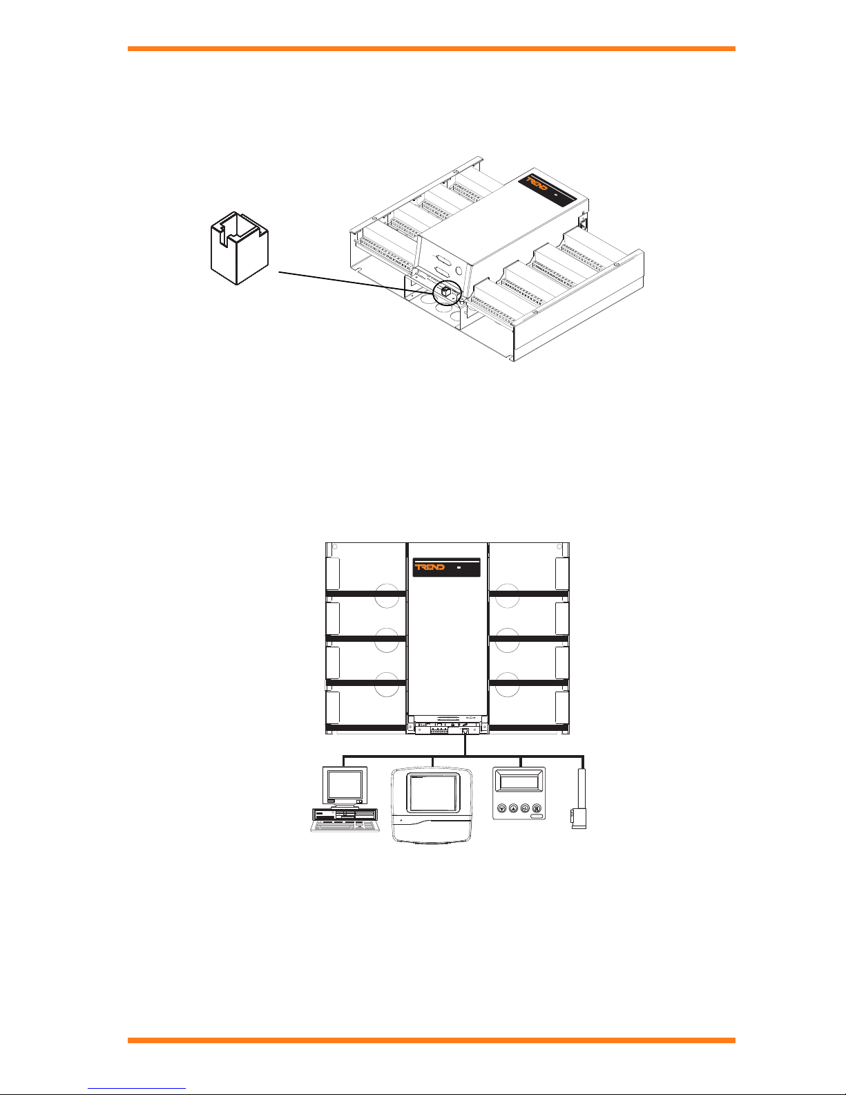
Communications: When operating as part of a Building Management System, the IQ251 will be connected to other devices using the
IQ system Network. This means that information within the IQ251 can be accessed using one of the IQ system supervisor programs, or
passed to other IQ controllers using inter-controller communications, enabling the sharing of information across the whole system.
When connected to the network the controller can use up to 3 different addresses. One address is for the controller itself (set by front
panel switch) the second and third are optional, and are for the locally connected supervisors (supervisor port address), (ndp port
address). Thus a locally connected supervisor has its own network address when connected to the network using the controller.
The controller’s address is set by a switch, and the supervisor and ndp port adresses are set up in the strategy configuration
(address module).
Battery Status: The IQ251 has a battery status checking circuit that checks the battery on power up and thereafter every midnight
and sets byte 506 bit 0 if the voltage has falls below a threshold value. This bit being set indicates that the battery needs to be changed.
It should be used within the strategy to generate an alarm (e.g. critical alarm). The battery should be changed after the first indication.
The battery will have a typical life of 10 years at 20 °C (68 °F). It is recommended that the battery is replaced every 5 years.
HARDWARE
Unit: The IQ251 has a metal chassis and a metal front cover. The
I/O modules are of aluminium extrusion. The I/O modules are fitted
to the controller by snapping off a section in the cover and removing
the relevant side plate. The module connector then slides into a
socket on the controller. There is an option to fit a 16 terminal earthing
(grounding) bar below each I/O module for cable screens (Part/
LA102359K). Cable access is using holes in the rear plate, or from
top or bottom, cables can be run down the central column behind
the controller board. Cleats are fitted to the rear plate to facilitate
cable mounting. There is a 25 Way D type knockout on the bottom
of the front panel for RS232 connection to an auxiliary node, and
a circular knockout for M20 gland or grommet for internetwork,
PSTN, ISDN or Lon cables. If required the IQ251 can be fitted in an
IP55 metal enclosure (ENCLS).
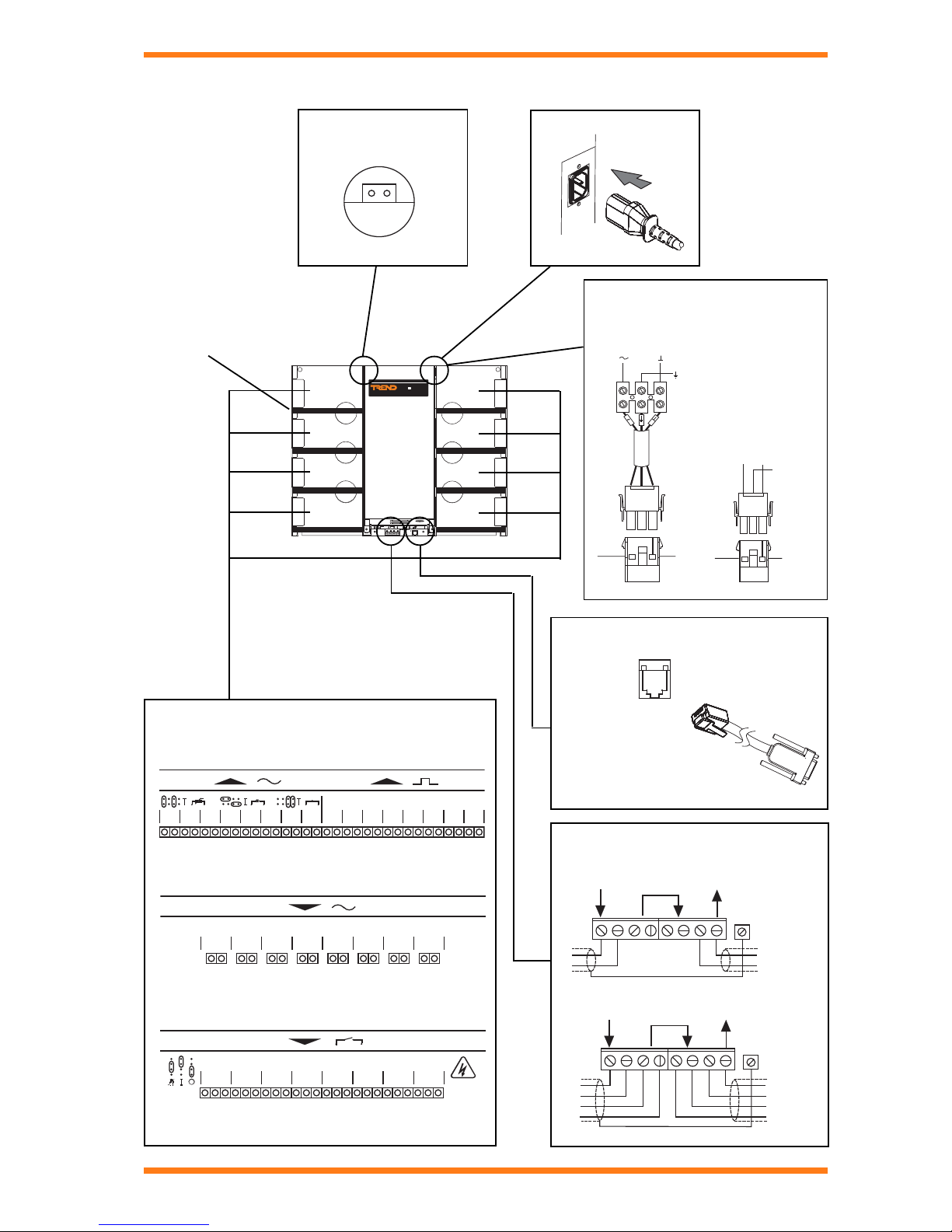
Connectors: Two part connectors are used throughout to facilitate
wiring. A busbar is provided for screen termination.
Power: 230 Vac 50/60 Hz, 24 Vac 50/60 Hz, or 24 Vdc. The 24 Vac
input power must be isolated and can only power 1 controller. The
24 Vdc input power may be earthed (grounded) but polarity must be
correct; it can power several controllers in parallel.
Fusing: The controller has no replaceable fuses; protection is
providedbymeans of a self-resetting thermally protected transformer.
The 24 V ac or dc versions have a 4A replaceable 1¼” fuse fitted
in line of input power cable inside the unit and a solid state multifuse.
The I/O modules are also individually protected against short circuits.
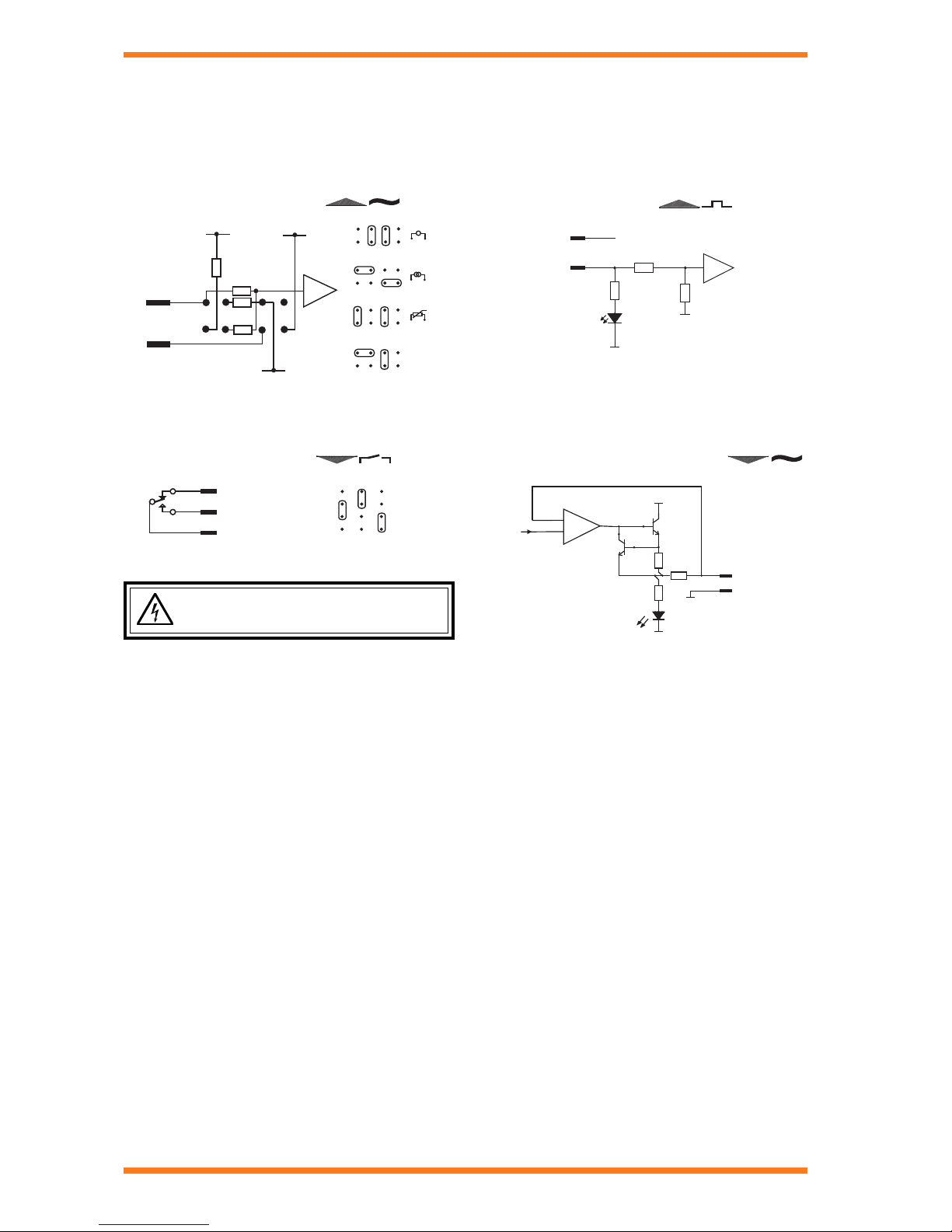
Indicators: LED indicators for receive and transmit network current flow
(RX, TX) and network OK ( ), also for power ( ), all I/O channels ( ),
and watchdog ( ). See specification section for details.
Network: The network terminals facilitate connection of 2 or 4 wire
cables. The standard IQ system node features are included (TX,
RX, and network OK, , indicators, bypass relay, and network alarm
generation). There is also the facility for connection of a supervisor
and integral network display panel to the network using the controller
without the need for additional node controllers.
Note that the IQ251 does not have a balanced line transmitter
like other IQ2 series controllers and this may result in reduced
network resilience.
Address/Baud rate switch: The address on the Lan is set by
poles 1 to 7 in range 1, 4 to 9, 11 to 119 and must be unique on
the Lan. The baud rate is set by poles 8 to 10 in the range 1k2,
9k6, 19k2 and must match the other nodes on the Lan. The
address/baud rate switch may also be used to perform a strategy
cleardown; this is done by setting all the address/baud rate poles
to zero before power up (see Installation Instructions, TG103483
sheet 4 and IQ Configuration Manual Addendum). For this reason
the address should normally be set non-zero.
These loads can be calculated as follows:
Input module
8 digital inputs @ 8 mA per channel
8 analogue inputs @ 20 mA per channel (thermistor and
voltage inputs can be ignored)
Max total for whole I/O module = (8x8)+(20x8) = 224 mA
Output module
8 analogue outputs @ 20 mA per channel
Max total for whole board = 20x8 = 160 mA
8 digital outputs @ 24 mA per channel
Max total for whole I/O module = 24x8 = 192 mA
Integral Node (e.g. TMN) = 250 mA.
(For consumption of other nodes see the respective data sheet).
For example:
IQ251 with 4 input I/O modules, 2 digital output I/O modules, 2
analogue output I/O modules, an integral NDP, and an MNC.
How much current is available from the auxiliary output supply?
Current consumed:
4 input I/O modules (all analogues are current) 4 x 224 =896 mA
2 digital output I/O modules 2 x 192 mA=384 mA
2 analogue output I/O modules (at max). 2 x 160 mA=320 mA
1TMN 250 mA
Total 1850 mA
Current available: 2100 - 1850 =250 mA
Battery Backup: Details about the strategy configuration, time
and date, and logged data are stored in RAM. A plug-in lithium
cell provides power to maintain the data in the event of power
failure, or the controller being switched off.
Auxiliary output supply: There is a 24 Vdc auxiliary output
supply provided on the input power board to power external relay
modules, sensors, etc. It is thermally protected and can provide
a maximum of 500 mA. This will normally be available, but if the
IQ251 has a full complement of I/O modules, and an integral
comms node fitted the amount of auxiliary power available for
other purposes will have to be calculated. The 24 Vdc input
power in the IQ251 has 2100 mA available after deduction of
current required for main board and network. This has to power I/O
modules, integral node, and the 24 Vdc auxiliary output supply.
I/O
node
AUX
variable
(e.g. 250) optional
500 mA (maximum)
2100 mA

4IQ251 Controller Data Sheet TA102315 Issue 4, 8/10/08
IQ251 Data Sheet
IN
C
0V
8
8
1
6
Externally powered current
sensor
100K
250R
10K
5V 24V
100K
Yellow
C
IN
24V
100K
0V
0V
27K
4K7
OUT
COM
Yellow
100R
22R
3K9
0V
0V
+24
HARDWARE (continued)
I/O modules: The IQ251 has a range of I/O modules which may be fitted in any combination in the 8 I/O slots. The range comprises
an 8 analogue and 8 digital input module (EIN), an 8 analogue output module (EAO), and an 8 digital output module (EDO).
Inputs: The input channel combination is dependent on the number of input modules fitted. Each EIN module provides 8 analogue,
and 8 digital inputs.
Analogue Input (8 identical channels) Digital Input (8 identical channels)
Outputs: The output channel combination is dependent on the output modules fitted. There are two different modules; the EDO
which provides 8 digital outputs, and the EAO which provides 8 analogue voltage outputs. An IQ system 2VID interface module
can be used in conjunction with 2 analogue voltage outputs to provide 2 analogue current outputs.
Digital Output (8 identical channels) Analogue Voltage Output (8 identical channels)
Digital outputs have manual override facilities as indicated above.
Warning: High voltage may be present.
Isolate elsewhere.
N/O
C
N/C
Auto OFF
ON

5
IQ251 Controller Data Sheet TA102315 Issue 4, 8/10/08
Data Sheet IQ251
IQ251
RX
TX
HARDWARE (continued)
Local Supervisor: The IQ251 has a local supervisor port on the front panel (RJ11). This corresponds to the local supervisor port
address provided by the IQ251:
Supervisor: A PC running a IQ system Supervisor, Engineering tool, wireless sensor receiver XW/R/IQ, or an IQView can be connected
to the network using the controller’s supervisor port without the need for an additional node controller although it does have its own network
address. When connected in this way the supervisor will have access to all devices on the network, and will function as if it were connected
using its own node controller. A wall mounting display, room display (RD), or smart display unit (SDU) may be connected to the local
supervisor port. Both displays monitor and adjust parameters in the local IQ251 only. The RD enables temperature setpoint display and
adjustment with options for occupancy override and fan speed adjustment (see order codes section). The SDU enables monitor and
adjustment of selected parameters. Only one single device (PC, IQView, RD, SDU, or XW/R/IQ) may be connected to the supervisor port
at one time.
The diagram below illustrates the combinations in which local supervisors/engineering tools and displays can be connected.
PC, IQView, RD or SDU, XW/R/IQ
(connected using supervisor port,
1 item only)
IQ251
local supervisor port (RJ11)

6IQ251 Controller Data Sheet TA102315 Issue 4, 8/10/08
IQ251 Data Sheet
HARDWARE (continued)
Integral Node :If required an additional node controller (e.g. TMNH, TMNE, CNC2, PNC2, INC2, LINC/FTT) may be fitted inside the
IQ251 using the node mounting kit. KIT/NODE/IQ25x.
The mounting kit contains nylon pillars which are screwed into
the 4 aluminium threaded inserts on the IQ251. The node card
has 4 semi-circular cutouts that fit between the mounting screws;
the screws are then tightened to clamp the board. There is a
special 24 Vdc power connection (labelled XNC) and a network
connector (labelled MNC). The two on-board network links must
be removed to enable the network to connect to the node.
Note that an additional node controller will consume current from
the 24 Vdc auxiliary output supply; see auxiliary output supply
section above and appropriate node controller data sheet.
There is a front panel knockout for RS232 to auxiliary node, and
a circular knockout for other auxiliary node cables. ADDRESS
ON
node power
(XNC)
network links
node network
connection
(MNC)
additional node position 4 cutouts
COMPATIBILITY
Supervisors: 916, IQView.
Utility software: SET.
Controllers: It can communicate to other IQ system controllers using inter-controller communications.
Interface: It can be connected to IQ system interface modules. Check interface module specification to ensure
compatibility.
Local Display: IQView, SDU,RD.
The IQ Configuration Reference Manual Addendum covers the compatibility between different types of strategy files, and between
the IQ251 sensor logs, and supervisors and software tools.
FIELD MAINTENANCE
The IQ Controller requires virtually no routine maintenance, however it is recommended that the lithium battery be replaced every
5 years, as explained in the IQ251 Installation Instructions, TG103483.
INSTALLATION
The IQ251 Controller is installed in a cabinet or panel using 4 screws and washers. For IQ251/USA, the unit is UL rated as ‘UL916,
listed open energy management equipment’. The procedure involves:
Mounting the controller in position
Fitting earthing (grounding) bars (if required)
Routing and tying cables
Fitting I/O modules
Connecting I/O
Connecting power, do not switch on
Connecting network
Connecting auxiliary output supply output (if used)
Isolating and disconnecting I/O
Setting network address and baud rate
Linking analogue input channels
Fitting link headers (if required)
Setting digital output links (if required)
Switching On
Checking controller
Checking network
Configuring strategy
Checking operation
Backing up strategy
Closing panel
The installation procedure is covered in the IQ251 Installation Instructions (TG103483). Fitting an integral node is covered by
KIT/NODE/IQ25x installation instructions (TG200595)

7
IQ251 Controller Data Sheet TA102315 Issue 4, 8/10/08
Data Sheet IQ251
IQ251
RX
TX
optional earthing
(grounding) bars
INSTALLATION
CONNECTIONS Auxiliary output supply
24 Vdc at 500 mA
24 Vdc 0 V
24 Vac:
24 Vdc:
24 Vac
Earth
+24V 0V
Black
Red
White
0V
24 V version
Mat-N-Loc to terminal adaptor (supplied)
EJ105383
24V
Earth
/USA only
2 part Mat-N-Loc
connector (supplied)
Network
T -
e a r t h i n g b a r
T + R - R +
N E T W O R K
T - T + R - R +
O U T I N
4 wire
T -
e a r t h i n g b a r
T + R - R + T - T + R - R +
N E T W O R K
O U T I N
2 wire
Inputs and Outputs
8
A O 1
O U T
C
A O 2
O U T C
A O 3
O U T C
A O 4
O U T C
A O 5
O U T C
A O 6
O U T C
A O 7
O U T C
A O 8
O U T C
Analogue Outputs (EAO module)
8
D O 2 D O 3 D O 4 D O 5 D O 6 D O 7 D O 8D O 1
C N o N c C N o N c C N o N c C N o N c C N o N c C N o N c C N o N c C N o N c
C A U T IO N
H I G H V O L T A G E
M A Y B E P R E S E N T
I S O L A T E E L S E H E R E
Digital Outputs (EDO module)
8 8
A I 1
I N C
A I 2
I N C
A I 3
I N C
A I 4
I N C
A I 5
I N C
A I 6
I N C
A I 7
I N C
A I 8
I N C
D I 1
I N C
D I 2
I N C
D I 3
I N C
D I 4
I N C
D I 5
I N C
D I 6
I N C
D I 7
I N C
D I 8
I N C
Inputs (EIN module)
Local Supervisor Port
RJ11 to 9 way ‘D
type’ female cable
CABLE/EJ101442
RJ11
(FCC68)
/230 version
IEC

8IQ251 Controller Data Sheet TA102315 Issue 4, 8/10/08
IQ251 Data Sheet
WEEE Directive :
At the end of their useful life the packaging,
product, and batteries should be disposed of
by a suitable recycling centre.
Do not dispose of with normal household waste.
Do not burn.
DISPOSAL
COSHH (Control of Substances Hazardous to Health - UK
Government Regulations 2002) ASSESSMENT FOR DISPOSAL
OF IQ251 Controllers. The only part affected is the lithium battery
which must be disposed of in a controlled way.
RECYCLING.
All plastic and metal parts are recyclable. The printed circuit
board may be sent to any PCB recovery contractor to recover
some of the components for any metals such as gold and silver.

9
IQ251 Controller Data Sheet TA102315 Issue 4, 8/10/08
Data Sheet IQ251
ORDER CODES
Non USA versions
IQ251/[Node]/[Power]
e.g. IQ251/TMNH/230 Specifies an IQ251 with integral modem node, and 230 Vac input power.
Controller comes complete with input power cable and moulded IEC connector (230 V) or screw terminal adaptor and MAT-N-LOC
connector (24 V).
Note that I/O modules for the IQ251 must be ordered separately, see below
USA Versions
Non USA Order Code USA Order Code
IQ251/USA/UL/24VAC 882000000 UL rated IQ251 Controller.
IQ251/TMNH/USA/UL/24VAC 882000010 UL rated IQ251 Controller with TMNH modem.
I/O Modues
Non USA Order Code USA Order Code
EIN 882000040 I/O module for IQ251 with 8 analogue and 8 digital inputs.
EAO 882000050 I/O module for IQ251 with 8 analogue outputs.
EDO 882000040 I/O module for IQ251 with digital outputs.
Accessories
Non USA Order Code USA Order Code
PART/LA102359K not available in USA Earthing (grounding) bar with mounting screw and nuts and
bag of earthing (grounding) screws.
KIT/NODE/IQ25x 882000080 Kit for mounting an auxiliary node card in IQ251 (appropriate
node cards listed above; node card must be ordered
separately).
ENCLS not available in USA 600 mm x 600 mm x 210 mm IP55 enclosure.
CABLE/EJ101442 not available in USA Adaptor cable RJ11 to 9 Way D type female for local PC connection.
]edoN[ ]rewoP[
knalbedonoN032ylppusrewopcaV032
HNMTmedomlargetnignidulcniedoNCAV42ylppusrewopcaV42
ENMTmedomlanretxerofedoNCDV42ylppusrewopcdV42
2CNCkrowtendnerTrofedoN
2CNPretnirpetomerrofedoN
2CNIkrowtenretnIdnerTrofedoN
TTF/CNILkrowtenskroWnoLrofedoN

10 IQ251 Controller Data Sheet TA102315 Issue 4, 8/10/08
IQ251 Data Sheet
ORDER CODES (continued)
Other Displays
Non USA Order Code USA Order Code
SDU/IQ not available in USA Smart Display Unit for wall mounting enabling monitoring and
adjustment of parameters.
RD/IQ/K not available in USA Room Display Unit for wall mounting, including temperature,
setpoint display and adjustment.
RD/IQ/KOS not available in USA Room Display Unit for wall mounting, including temperature,
setpoint display and adjustment, and occupancy override.
RD/IQ/KOSF not available in USA Room Display Unit for wall mounting, including temperature,
setpoint display and adjustment, occupancy override, and
fan speed adjustment.
SDU/IQ/WSA/USA 882001470 Smart Display Unit for wall mounting enabling monitoring
and adjustment of parameters plus wall adaptor plate for US
wall boxes.
RD/IQ/K/WSA/USA 882001500 Room Display Unit for wall mounting, including temperature,
setpoint display and adjustment plus wall adaptor plate for
US wall boxes.
RD/IQ/KOS/WSA/USA 882001240 Room Display Unit for wall mounting, including temperature,
setpoint display and adjustment, and occupancy override
plus wall adaptor plate for US wall boxes.
RD/IQ/KOSF/WSA/USA 882001550 Room Display Unit for wall mounting, including temperature,
setpoint display and adjustment, occupancy override, and
fan speed adjustment plus wall adaptor plate for US wall
boxes.

11
IQ251 Controller Data Sheet TA102315 Issue 4, 8/10/08
Data Sheet IQ251
SPECIFICATIONS
CONTROLLER
Electrical
CPU :68EC020 32 bit processor
CPU speed :16.67 MHz
Cycle time :1 s
Memory :512 kbyte battery-backed SRAM, and
512 kbyte flash.
Input power
230 :230 Vac, +15% -10%, 50 to 60 Hz
/24VAC :24 Vac, +25% -10%, 50 to 60 Hz (24 Vac
input power must be isolated)
/24VDC :24 Vdc, +25% -10%, (24 V to 36 Vdc)
Auxiliary output supply :24 Vdc ±10% 500 mA maximum (typical)
dependent on configuration (see auxiliary
output supply section for details)
Consumption :100 VA maximum
Fusing
/230 :No replaceable fuses required. All
protection self resetting.
/24VAC, /24VDC:4A 1¼” replaceable fuse fitted in line of
input power cable inside unit.
Battery backup :Battery maintains time, and logged data
with input powers off for at least 5 years.
Battery :CR2032, 3 V, or equivalent
Clock accuracy :30 s per month (typical).
Network :20 mA serial 2 wire current loop, opto
isolated, polarity independent receiver.
Supervisor transmission:RS232, EIA/TIA/232E, V28
Distance
Supervisor :15 m (16 yds)
Network :Dependent on cable type, see table
below.
Baud rate
Network :Selectable by switch 1k2, 9k6, or 19k2,
set to be the same as other nodes on
Lan.
Supervisor :9k6.
Network addresses
Controller :Selectable by switch, 116 nodes
addressable (1,4 to 119 excluding 10)
set to be unique on Lan.
Supervisor port :Software selectable, 116 nodes
addressable (1, 4 to 119 excluding 10)
set to be unique on Lan
NDP port :Software Selectable, 116 nodes
addressable (1,4 to 119 excluding 10)
set to be unique on Lan.
Input or
Output modules :8 modules in total. Any module type may
be fitted in any position. Module types
are:
EIN :8 analogue and 8 digital inputs
EAO :8 analogue outputs
EDO :8 digital outputs
Mechanical
Dimensions :550 mm (21.7”) x 440 mm (17.32”) x
175 mm (6.9”)
Material
Chassis :Zinc plated and passivated mild steel
I/O modules :Extruded aluminium with alocrom finish.
Cover :Fire retardant moulded ABS.
Protection :IP20
Weight :14.5 kg (32 lbs) (fully loaded)
Connector
I/O modules :2 part connector, 50 mm (1.97”) half pitch
Power
/230 :IEC plug
/24VAC, /24VDC :Mat-N-Loc to screw terminal adaptor
Network :2 part connector with 8 screw terminals
for 0.5 to 2.5 mm2cross section area (14
to 20 AWG) cable.
Supervisor :RJ11 (FCC68), 6 pin, for IQ system utility
software connected using adaptor cable
CABLE/EJ101442.
Environmental
EMC
Emissions :EN50081-1.
Immunity :prEN50082-2.
Safety :EN61010.
Ambient limits
Storage :-10 °C (14 °F) to 50 °C (122 °F)
Operating :0 °C (32 °F) to 45 °C (113 °F)
Humidity :0 to 90 %RH non-condensing
UL :(IQ251/USA only). The unit is UL rated
as ‘UL916, listed open energy
management equipment’.
Indicator Lamps
PWR :(green) ON when input power is
connected.
WD :(red) ON if controller has a software fault.
I/O :(red) Flashes during normal operation.
LAN :(green) ON if network is operating.
Flashes if prohibited controller network
address set (0, 2, 3, >119).
TX :(yellow) ON if current is flowing from the
network transmitter.
RX :(yellow) ON if current is entering the
network receiver.
elbaCduab2k1duab6k9duab2k91seriWfo.oN
2819nedleB m0001
)sdy0901(
m0001
)sdy0901(
m007
)sdy567( 2
7029nedleB m0001
)sdy0901(
m0001
)sdy0901(
m005
)sdy545( 2
metsysQI
002/FH/22/1/1/PT
)1678nedleB(
m0001
)sdy0901(
m007
)sdy567(
m053
)sdy083( 2
metsysQI
002/FH/22/2/2/PT
)3278nedleB(
m0001
)sdy0901(
m005
)sdy545(
m052
)sdy072( 4

IQ251 Data Sheet
12 IQ251 Controller Data Sheet TA102315 Issue 4, 8/10/08
Trend Control Systems Limited
P.O. Box 34, Horsham, West Sussex, RH12 2YF, UK. Tel:+44 (0)1403 211888 Fax:+44 (0)1403 241608 www.trend-controls.com
Trend Control Systems USA
6670 185th Avenue NE, Redmond, Washington 98052, USA. Tel: (425)897-3900, Fax: (425)869-8445 www.trend-controls.com
© 2008 Honeywell Technologies Sàrl, ECC Division. All rights reserved. Manufactured for and on behalf of the Environmental and Combustion Controls
Division of Honeywell Technologies Sàrl, Ecublens, Route du Bois 3, Switzerland by its Authorized Representative, Trend Control Systems Limited.
Trend Control Systems Limited reserves the right to revise this publication from time to time and make changes to the content hereof without
obligation to notify any person of such revisions or changes.
SPECIFICATIONS (continued)
I/O MODULES
All
Dimensions :72 mm (2.83”) x 202 mm (7.95”) x 43 mm
(1.69”)
Weight :0.3 kg approx. (0.66 lbs)
Connector
Main board :2 part connector, 50 mm (1.97”) half pitch
Inputs/Outputs :2 part connector screw terminals for 0.5
to 2.5 mm2cross section area (20 to
14 AWG) cable.
Signal Cable :Analogue Voltage, Current, Thermistor,
or Digital inputs, and Analogue outputs. IQ
system TP/1/1/22/HF/200 recommended
(Belden 8761)
8 Analogue, 8 Digital Input Module (/EIN/)
Analogue inputs :12 bit resolution (4096 steps). Minimum
60 dB series mode rejection at frequency
of input power supply. Linkable for
analogue current (I), analogue voltage
(V), or thermistor (T)
V :0 to 10 V input resistance 200 kΩ,
accuracy 50 mV equivalent to ±0.5% of
span.
I :0 to 20 mA input resistance 250 Ω0.1%,
accuracy 0.5 % of span (i.e. 100 μA)
T :Thermistor, bridge resistor 10 kΩ0.1%,
accuracy 0.5 % of span. Bridge input
power 5V.
Digital inputs :Volt free contact, or 24 Vdc self powered
contact. Wetting current 5 mA @ 24 Vdc,
count rate 32 Hz max.
Status LED :(yellow) One per digital input. ON if input
is closed
8 Analogue Output Module (/EAO/)
Analogue outputs :8 bit resolution (256 steps). 0 to 10 V
with 20 mA current limit, accuracy ±50 mV
equivalent to ±0.5 % span.
Status LED :(yellow) 1 per channel. Light intensity
increases with output voltage.
8 Digital Output Module (/EDO/)
Digital outputs :Single pole change over relay, contacts
rated for 240 Vac single phase throughout
only 7 A (resistive load), 5 A (inductive,
CosØ>=0.4), 30 Vdc at 5 A (resistive
load), reduce to 2 A for 24 Vdc (inductive
load, T<=30 mS). Arc suppression
recommended, see Relay Output Arc
suppression Installation Instructions,
TG200208). IQ251/USA only: Relay
outputs are UL rated up to 30 V.
Status LED :(yellow) 1 per channel. ON when relay is
energised.
Manual override :Each channel is linkable for ON, OFF,
or AUTO.
Version This document covers
Firmware :V3 or greater
Boards
EIN :AM101687 v3
EAO :AM101721 v1.1
EDO :AM102022 v1.1
CPU :AM101701 v1
PSU :AM102060 v2.2
Other manuals for IQ251
1
Table of contents
Other TREND Control Unit manuals
Popular Control Unit manuals by other brands

Zoeller
Zoeller 4000 Series owner's manual

Siemens
Siemens SIRIUS PROFINET manual

Intertec Data Systems
Intertec Data Systems MPR-A Series instruction sheet

Volth
Volth ARGO HYTOS SD2E2X-B2 operating instructions

Smartflow
Smartflow Swap SPV8-A-M Installation and operating instructions

Allen-Bradley
Allen-Bradley Micrologix 1500 installation instructions