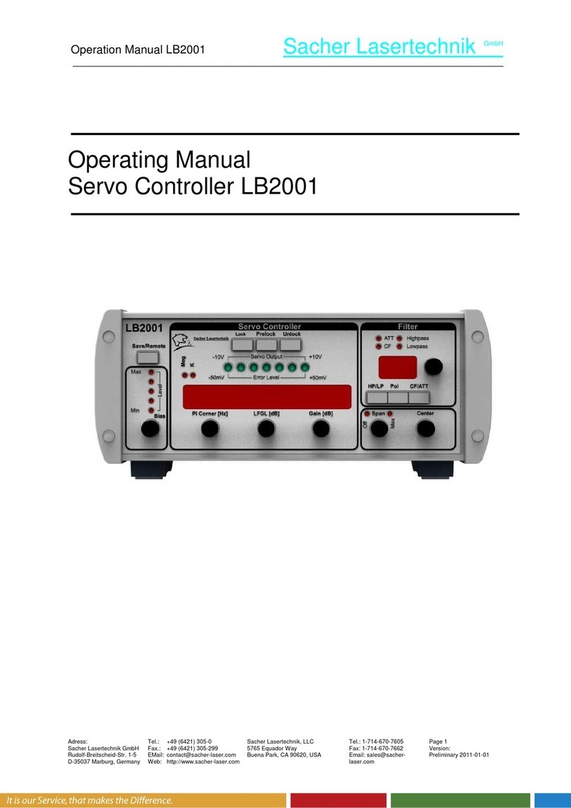
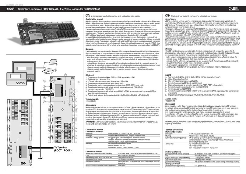
TRENT CaterSense V2 Installation and operation manual

CaterSense the Intelligent answer
CS-INSTV2-0.01 Page 1 01-15
Model: CaterSense V2
CaterSense V2 &
CS-V2+ATSC-02-08
MULTI FUNCTION
GAS SUPPLY CONTROLLER
INSTALLATION and COMMISSIONING
INSTRUCTIONS

CaterSense the Intelligent answer
CS-INSTV2-0.01 Page 2 01-15
Model: CaterSense V2
Product Overview
The CaterSense system is based on a range of products and ancillary equipment designed to meet the
ever changing requirements of the catering industry and associated regulations.
CaterSense V2 intelligent controller with Multi function solutions
The controller has a unique “self-set” system which makes for easy system commissioning.
Contents
1.0 General Info
1.01 Opening the unit
1.02 Fixing details
1.02.A Standard control unit
1.02.B Inbuilt speed control unit
1.03 Cable entry
1.03.A Standard control unit
1.03.B Inbuilt speed control unit
1.04 Electrical connections
1.04.A Standard control unit
1.04.B Inbuilt speed control unit
1.05 System set-up (locations)
2.0 Set-up and commissioning
2.01 Initial Set-up
2.02 System Set-up
2.03 System Checking
2.04 Functional Operation
2.05 Troubleshooting

CaterSense the Intelligent answer
CS-INSTV2-0.01 Page 3 01-15
Model: CaterSense V2
1.0 General Information
1.01 Opening the unit
1) To open the enclosure, first remove the snap-in clips at the bottom of the two side
panels: using a flat bladed screwdriver push the clip from below away from each side
panel.
2) Press the release pad on each side at the bottom of the enclosure and lift off each
side panel in turn by first pulling the bottom towards you. This will reveal the four
facia plate fixing screws.
X 2
1.
2.
3.

CaterSense the Intelligent answer
CS-INSTV2-0.01 Page 4 01-15
Model: CaterSense V2
3) Unscrew these four screws and lift the facia plate from the back box, ensuring that the
ribbon cable between the two PCBs has been unplugged at the main PCB end.
Place the screws, snap-in clips, side panels and facia plate in a safe place until the back box
has been fixed, wired and is ready for reassembly and set-up
*Please note if using a CaterSense V2 with inbuilt twin speed control you will
also need to remove the top plate (4) and front control box (5) as shown in the
diagrams below.
* IMPORTANT – Please ensure that when reassembling the CaterSense V2 with
inbuilt speed control unit that both the main power plug and control cable plug
are firmly fitted before powering the unit.
4.
5.

CaterSense the Intelligent answer
CS-INSTV2-0.01 Page 5 01-15
Model: CaterSense V2
1.02 Fixing details
1.02A For standard control unit:
The CaterSense V2 unit has six (6) mounting holes which can be used (as shown below)
Note: Ensure that the enclosure is mounted on a clean and level surface away from the direct cooking
area or wet surfaces.
1.02B For inbuilt speed control unit:
The CaterSense V2 + ATSC unit has four (4) mounting holes which can be used (see
Diagram 2)
Note: Ensure that the enclosure is mounted on a clean and level surface away from the direct cooking
area or sinks and other wet areas.
223
248
92.5
235
111.5
53
48
Diagram 2: Fixing details
168
230
244
BOTTOM
TOP
200
270
48

CaterSense the Intelligent answer
CS-INSTV2-0.01 Page 6 01-15
Model: CaterSense V2
1.03 Cable entry
1.03A For standard control unit:
The CaterSense V2 enclosure has an area of 190 x 25 mm which can be drilled for conduit
entry on the top edge of the enclosure.
1.03B For inbuilt speed control unit:
The CaterSense V2 & ATSC has two main areas for cable entry: the top area (223 x 40mm)
and the back of the enclosure (130 x 30mm located at the top).
For ease of installation, most of the connections you will need are made in the enclosure for
the ATSC. The inter-connections between the ATSC and the CaterSense controller are
achieved via two pre-made cable looms.
1.04 Electrical connections
1.04A For standard control unit:
The CaterSense system has two sets of terminals all mounted along the top edge of the main
PCB circuit board.
Terminals 1 to 22 are the smaller terminals (1.5 mm² cable) and are used for the
sensors, inter-locking devices, remote speed and on/off control,
screened cable must be used (we recommend Beldon 8723 but
that should be the choice of the installer and dependant on the
individual installation).
Terminals 23 to 34 are the larger terminals (4 mm² cable) and are for the power
connections for the fans, gas valve and power supply to the unit.
The terminals are of the rising clamp type protection.
All cabling should be kept to the top of the unit within the designated area. No cables should
be placed or laid across the PCBs as this may cause damage.
SENSOR 1 SENSOR 2 FIRE
ALARM
REMOTE
KOPB
CONTROL OUTPUTS
VOLT-FREE
OP1 OP2
CONTROL OUTPUTS
0-10V SPEED SIGNAL
OP3 OP4
START / STOP
POWER SIGNALS
FAN 1 FAN 2
GAS VALVE
OUTPUT
POWER
SUPPLY
E NL
E N
L
E E L NL N
1 2 3 4 5 6 7 8 9 10 11 12 13 14 15 16 17 18 19 20 21 22 23 24 25 26 27 28 29 30 31 32 33 34
REMOVE JUMPER LINK TO ACTIVATE DEVICE
J27 J26 J23 J25
4 Amp Max
24v 0vS+ S- 24v 0vS+ S- S+ 0v Scr S+ 0v Scr
1.04B For inbuilt speed control unit:
The ATSC-02-xx system has two sets of terminals all mounted along the top edge of the main
PCB circuit board.
Terminals 1 to 16, are the smaller terminals (1.5 mm² cable) and are used for the
sensors and inter-locking devices including motor thermal contacts.
Screened cable must be used (we recommend Beldon 8723 but
that should be the choice of the installer and dependant on the
individual installation).

CaterSense the Intelligent answer
CS-INSTV2-0.01 Page 7 01-15
Model: CaterSense V2
Remaining Terminals are the larger terminals (4 mm² cable) and are for the power
connections for the fans, gas valve and power supply to the unit.
The terminals are of the rising clamp type with protection.
All cabling should be kept to the top of the unit within the designated area. No cables should
be placed or laid across the PCBs as this may cause damage.
1.05 System set-up
The CaterSense V2 unit has a number of intelligent control solutions. Each of which is set via
a DIL (DIP) switch mounted on the main PCB circuit board. The CaterSense also has a
unique “Self-set” system commissioning tool which makes for easy system commissioning.
These devices are located on the main PCB as detailed in Diagram 3.
2.0 Set-up and Commissioning
The set-up and commissioning of your CaterSense system is in two parts, Initial and
System.
2.01 Initial Set-up
Once all of the wiring has been completed and tested and the system is ready to be set-up
and commissioned, the following sequence MUST be followed to ensure the CaterSense and
system operate correctly.
OFF
ON
1 2 3 4
R113
R114
SENSOR 1
SENSOR 2
KNOCK-OFF
FIRE ALARM
SET-UP
CONTROLLER
MODE DIL SWITCH
SYSTEM
SET-POINT 2
SYSTEM
SET-POINT 1
INPUT SELECTION
JUMPERS
ENGINEERS SYSTEM
SELF-SET BUTTON
MAIN PCB
SINGLE FAN
RIBBON CABLE
SOCKET
J27
J26
J25
J23
J13
J5J3
Diagram 3: PCB locations

Sensor 4
Sensor 3
Sensor 2
J8
J7
SMALL EXPANSION MODULE
IF REQUIRED
FIRE
ALARM
KNOCK
OFF
(open on l rm)
Sensor 1
8765
4321
34
CATERSENSE V2 - MAIN PCB
33
EXTRACT
FAN
SUPPLY
FAN
32
E
313029
L N
282726252423
22212019
E
181716
L N
1514131211109876543
E
2
L N
GAS
SOLENOID
VALVE
1
Tel: 01782 - 844688 F x: 01782 - 844772
JH-PCS-WD-V2
E L N
9876543210
DATE: DRAWING No: DRAWN BY
AUTOMATIC SPEED
CONTROL OUTPUT
(0-10 / 5-10Vdc)
HEATER
BATTERY
OUTPUT
(0-10Vdc)
J5
J3
SENSOR 1
SENSOR 2
KNOCKOFF
FIRE ALARM
SINGLE
J27
J26
J25
J23
J13
SETUP
ON
OFF
1234
CATERSENSE V2
FAN SART
HEATER
BATTERY
ENABLE
*we recommen Bel on 8723 but
that shoul be the choice of the installer
an epen ant on the in ivi ual installation*
*
*
POWER SUPPLU
(240V c, 50Hz)
LOCAL
ISOLATOR
22/04/2015

MAIN (REGULATING)
AUXILIARY
NEUTRAL
EARTHE
C
A
M
CS-WD-V2S
LOCAL
ISOLATORS
(See Note: 1)
THERMAL
ENABLE
15 1613 14
- +
ALL TRIM POTS
ON
OFF
DRAWN BYDRAWING No:DATE:
0 1
NOTES:
MOTOR SPEED
AD USTMENT
POTS
RATIO
MTR 2 MTR 1
MAX SPDMIN SPD
2
L
345
N
E
6 7 8 9
POWER SUPPLY
(240Vac, 50 Hz,
See Note: 3)
PRE-WIRED CONNECTIONS
(LOW VOLTAGE)
PRE-WIRED CONNECTIONS
(240Vac)
L N
E
PWR IN
SCREEN CABLE
BELDON 8723 TYPE
E C A M
EE
CONNECTION DETAILS - ATSC PCB
INTERNAL
USE ONLY
LNNL
GAS
SOLENOID
VALVE
(open on alarm)
KNOCK
OFF
FIRE
ALARM
9 17 6 5
SUPPLY
FAN
EXTRACT
FAN
NL
E
101112 3 2
AUX OUT
L N
E
MOTOR 2 OUTPUTMOTOR 1 OUTPUT
E C A M
KNOCK
OFF
FIRE
ALARM SENSOR 2
0v
SIG
+24v
SENSOR 1
0v
SIG
+24v
Tel: 01782 - 844688 Fax: 01782 - 844772
CATERSENSE V2
TWIN SPEED CONTROLLER
WIRING & CONNECTION DIAGRAM H-P
1) LOCAL ISOLATION MUST BE PROVIDED IN ACCORDANCE
WITH THE CURRENT EDITION OF THE IEE REGULATIONS.
2) CHECK MANUFACTURER'S WIRING DETAILS FOR CORRECT
CONNECTIONS AND SET-UP REQUIREMENTS.
3) ENSURE THAT THE POWER SUPPLY IS CORRECTLY RATED
TO THE SIZE OF BOTH FAN MOTORS AND GAS VALVE
34
CATERSENSE V2 - MAIN PCB
3332313029282726252423
22212019181716151413121110987654321
5
3
SENSOR 1
SENSOR 2
KNOCKOFF
FIRE ALARM
SINGLE
27
26
25
23
13
SETUP
ON
OFF
1234
*we recommen Bel on 8723 but
that shoul be the choice of the installer
an epen ant on the in ivi ual installation*
18 18
*
SCREENED CABLE RECOMMENDED
THRM
SELECT
THERMAL
CUT OUT
(See Note: 6)
MOTOR 1
1413
COMMON
AUXILIARY WINDING
MAIN WINDING
ME
TYPICAL WIRING ARRANGEMENT FOR A
SINGLE PHASE MOTOR (3 WIRE - See Note: 5)
AC
LOCAL
ISOLATOR
(See Note: 1)
MOTOR 1
OUTPUT
Sensor 4Sensor 3
8
7
87654321
Sensor 2 Sensor 1
FAN START
HEATER
BATTERY
ENABLE
HEATER BATTERY
OUTPUT (0-10Vdc)
*
22/04/2015

Tel: 01782 - 844688 Fax: 01782 - 844772
JH-P
SENSORS-WD01
9876543210
DATE: DRAWING No: DRAWN BY
SENSOR CONNECTIONS
4 2 1
t
CAPILLAR
THERMOSTAT
(remove link if required,
open on low temp)
GW
E L N VAL3P.....VALVE
& ACTUATOR
flex
BLACK
WHITE
RED
B 1413NLE
3-PORT VALVE ADDITIONAL
CONNECTION BOX
CS-VPP-01
C
AIR DIFFERENTIAL
PRESSURE SWITCH
N/O
EXTRACT AIR
TEMPERATURE
SENSOR
CO2
SENSOR
SUPPL AIR
TEMPERATURE
SENSOR
GAS PRESSURE
TRANSDUCER
OUT 0v24v
1716
OUT 0v24v
G G01
OUT 0v24v
1 3 2
OUT 0v24v
132
22/04/2015

CaterSense the Intelligent answer
CS-INSTV2-0.01 Page 11 01-15
Model: CaterSense V2
a) DIL (DIP) switch set-up
Ensure the correct system code has been selected on the DIL switch.
IMPORTANT: Ensure power supply is switched OFF before adjusting DIL mode
switch
*Please note – If using manual or step transformer speed controllers,
ensure that DIL (DIP) switch 2 is in the disabled position.
1 2 3 4
Enable
Disable
DIL 1 Is used to enable or disable Gas Pressure Proving
DIL 2 Is used to enable or disable Automatic Fan Speed Control
DIL 3 Is used to enable or disable CO2 Monitoring
DIL 4 Is used to enable or disable System Demand
MODE DIL (DIP)
position
Fan Start /
Stop
Gas
pressure
proving
Automatic
fan speed
control
CO2
Monitoring
System
Demand
Heater battery control
LPHW only
Electric /
Gas fired
1
N/A Enable with
jumper J21
2
N/A Enable with
jumper J21
3
Enable with
jumper J21
4
N/A Enable with
jumper J21
5
Enable with
jumper J21
6
Enable with
jumper J21
7
N/A Enable with
jumper J21
8
Enable with
jumper J21
9
Enable with
jumper J21
10
Enable with
jumper J21
11
Enable with
jumper J21
12
Enable with
jumper J21
See Page 13

CaterSense the Intelligent answer
CS-INSTV2-0.01 Page 12 01-15
Model: CaterSense V2
b) Setpoint allocation and set-up
The CaterSense V2 has two 270° turn pots called R113 and R114 (as shown
below). These pots are used to allocate different setpoints dependent on the DIL (DIP) switch.
R114
R113
POTS Sensor Inputs
MODE DIL (DIP)
position R113 setpoint R114 Setpoint Sensor 1 Sensor 2 Sensor 3 Sensor 4
1
N/A Supply
Temperature N/A Supply
Temp sensor N/A N/A
2 N/A Supply
Temperature
Gas pressure
sensor
Supply
Temp sensor N/A N/A
3
N/A Supply
Temperature N/A Supply
Temp sensor N/A N/A
4 N/A Supply
Temperature
Supply Temp
sensor CO2 sensor N/A N/A
5 N/A Supply
Temperature
Gas pressure
sensor
Supply
Temp sensor N/A N/A
6 N/A Supply
Temperature
Supply Temp
sensor CO2 sensor N/A N/A
7 N/A Supply
Temperature
Gas pressure
sensor CO2 sensor Supply
Temp sensor N/A
8
N/A Supply
Temperature
Gas pressure
sensor CO2 sensor Supply
Temp sensor N/A
9 Demand
Temperature
Supply
Temperature
Supply Temp
sensor
Demand
Temp sensor N/A N/A
10 Demand
Temperature
Supply
Temperature
Gas pressure
sensor
Supply
Temp sensor
Demand
Temp sensor N/A
11 Demand
Temperature
Supply
Temperature
Supply Temp
sensor CO2 sensor Demand
Temp sensor N/A
12 Demand
Temperature
Supply
Temperature
Gas pressure
sensor CO2 sensor Supply
Temp sensor
Demand
Temp sensor

CaterSense the Intelligent answer
CS-INSTV2-0.01 Page 13 01-15
Model: CaterSense V2
* To enable the Electric or Gas Fired Heater Battery Control you must ensure the
jumper J21 is fitted as per image below.
(Jumper J21)
c) Input Jumpers / Sensor Links ON = OFF =
IMPORTANT: Ensure power supply is switched OFF before adjusting input jumpers
or sensor links.
J25 (KNOCKOFF) - If using a remote knockoff circuit in terminals 11 and 12, ensure that
J25 is OFF. Otherwise, ensure J25 is ON.
J23 (FIRE ALARM) - If using a fire alarm circuit in terminals 9 and 10 OR a fan hold-off
thermostat OR thermal cut outs are connected ensure that J23 is OFF. Otherwise, ensure
J23 is ON.
J13 (SINGLE) - If only using one fan, ensure J13 is ON. Otherwise, ensure J13 is OFF.
d) Inter-lock circuits
Ensure that the fire alarm and knock-off switches (if fitted) are all in the operational
position.
e) Gas pressure range
Whenever the system is initialised with the "start" pad, a pipework integrity test is carried
out. This opens the gas solenoid valve for 10 seconds, and then closes the valve for 30
seconds and monitors the pressure. If this pressure drops by 10% or more during this 30
seconds stage, the system will alarm and not start.
When all of the above stages have been
completed, re-assemble the CaterSense
unit by reversing the sequence described
above in section 1.01.
NOTE: Ensure the ribbon cable is plugged
in correctly with the key pin (red stripe) at
the top on the main PCB, and at the
bottom on the facia (see Diagram 5).
Otherwise this may cause damage to the
PCB and the unit will not function correctly.
Diagram 5: Ribbon cable

CaterSense the Intelligent answer
CS-INSTV2-0.01 Page 14 01-15
Model: CaterSense V2
2.02 System Set-up – CaterSense V2
Once the above has been carried out, the system is ready to be powered up.
Within the step-by-step sequence of set-up instructions the CaterSense unit will give you
feedback on the system via audible “beeps” and coloured LEDs.
Set-up sequence:
1) Activate "SETUP" mode on controller
2A) Manual speed control fan power monitoring set-up
OR
2B) Automatic speed control fan power monitoring set-up
OR
2C) Electronic speed control fan power monitoring set-up
3) CO2 monitoring alarm stages (if required)
4) Heater battery set-up (if required)
5) Demand extract air control set-up (if required)
The sequence detailed above MUST be followed to enable the CaterSense unit to program its
parameters. Ensure that the system is allowed to settle and become stable before moving on
to the next stage. DO NOT RUSH.

CaterSense the Intelligent answer
CS-INSTV2-0.01 Page 15 01-15
Model: CaterSense V2
1) Activate "SETUP" mode on controller
Then go to:
2A) Manual speed control fan power monitoring set-up
OR
2B) Automatic speed control fan power monitoring set-up
OR
2C) Electronic speed control fan power monitoring set-up
POWER ON GAS VALVE
SYSTEM CONDITION GAS PRESSURE
REMOTE KNOCK OFF FAN 1
FIRE ALARM / THERMAL FAN 2
CO2 MONITORING
Ensure LED’s status is as above then:-
PRESS SETUP
(Hold until system beep)
OFF
ON
1 2 3 4
R113
R114
SENSOR 1
SENSOR 2
KNOCK-OFF
FIRE ALARM
SET-UP
MAIN PCB
SINGLE FAN
J27
J26
J25
J23
J13
J5J3

CaterSense the Intelligent answer
CS-INSTV2-0.01 Page 16 01-15
Model: CaterSense V2
2A) Manual speed control fan power monitoring set-up
In this set-up the set-up button can be pressed numerous amount of times to
eliminate accidental or double presses.
Once the air balancing procedure has been carried out, ensure the fans are running. Set each
fan to the lowest speed and allow them to run and settle.
The system will produce a short beep. Change the speed of the fans to the next speed up.
Allow system to run and settle. (If using an analogue speed controller, split the space
between min and max speed into approx 10 equal parts).
Repeat this process until all fan speeds have been saved.
Once this has been successfully completed.
The set-up is now complete and the system is ready to run. However we recommend that the
system is run through the systems checking procedure (2.03) to ensure the unit is
successfully commissioned.
3) PRESS
SYSTEM
STOP
GAS SHUT OFF
POWER ON GAS VALVE
SYSTEM CONDITION GAS PRESSURE
REMOTE KNOCK OFF FAN 1
FIRE ALARM / THERMAL FAN 2
CO2 MONITORING
2) PRESS SYSTEM CONDITION
GAS VALVE
FAN 1, FAN 2
All other LEDs
1) PRESS SYSTEM CONDITION
GAS VALVE
FAN 1, FAN 2
All other LEDs

CaterSense the Intelligent answer
CS-INSTV2-0.01 Page 17 01-15
Model: CaterSense V2
2B) Automatic speed control fan power monitoring set-up
The CaterSense will then display the following.
The fans will start at full speed. Using the and pads in conjunction
with the min and max pots on the ATSC-02-xx PCB ensure that the system has been
correctly balanced, and you have correctly set the minimum and maximum speeds for each
fan.
The ratio pot adjusts the speed of fan 2 relative to fan 1, to allow you to balance the make-up
air with the amount of air extracted.
IMPORTANT: Ensure that you do not set the minimum speed to a level that will cause the
fan to overheat. Trent Products recommend a minimum voltage output to the fans of no less
than 140Vac between the "M" and "C" terminals on the speed control PCB. Consult the fan
manufacturer for more details. Once you have setup the fan speeds, return the fan speed to
maximum by using the ‘B’ button before continuing.
PRESS SETUP
POWER ON GAS VALVE
SYSTEM CONDITION GAS PRESSURE
REMOTE KNOCK OFF FAN 1
FIRE ALARM FAN 2
CO2 MONITORING
Diagram 5: Speed adjustment pots

CaterSense the Intelligent answer
CS-INSTV2-0.01 Page 18 01-15
Model: CaterSense V2
The system will produce a short beep. The CaterSense will slowly reduce the speed of the
fans to establish the characteristics of your system. DO NOT INTERRUPT THIS PROCESS.
After approximately two minutes, the system will have fully recorded the running currents of
your fans. If you have an electric or gas fired heater battery connected, the fans will run on
for a further 5 minutes. Otherwise, the fans will stop straight away.
POWER ON GAS VALVE
SYSTEM CONDITION GAS PRESSURE
REMOTE KNOCK OFF FAN 1
FIRE ALARM FAN 2
CO2 MONITORING
POWER ON GAS VALVE
SYSTEM CONDITION GAS PRESSURE
REMOTE KNOCK OFF FAN 1
FIRE ALARM / THERMAL FAN 2
CO2 MONITORING
FAN SPEED
UP
DOWN
UP
DOWN
2 mins

CaterSense the Intelligent answer
CS-INSTV2-0.01 Page 19 01-15
Model: CaterSense V2
2C) Electronic speed control fan power monitoring set-up
The CaterSense will then display the following.
The fans will start at full speed. Press and hold the For 5 seconds until the LED
display is as follows:
Using the and pads and a multi-meter between terminals 13 and 14
you can now set the minimum speed for fan 1 to 0 VDC.
The CaterSense will then display the following.
POWER ON GAS VALVE
SYSTEM CONDITION GAS PRESSURE
REMOTE KNOCK OFF FAN 1
FIRE ALARM FAN 2
CO2 MONITORING
PRESS SETUP
POWER ON GAS VALVE
SYSTEM CONDITION GAS PRESSURE
REMOTE KNOCK OFF FAN 1
FIRE ALARM FAN 2
CO2 MONITORING
POWER ON GAS VALVE
SYSTEM CONDITION GAS PRESSURE
REMOTE KNOCK OFF FAN 1
FIRE ALARM FAN 2
CO2 MONITORING

CaterSense the Intelligent answer
CS-INSTV2-0.01 Page 20 01-15
Model: CaterSense V2
Using the and pads and a multi-meter between terminals 13 and 14
you can now set the maximum speed for fan 1 to 10 VDC.
If you are using two fans you will need to repeat the above procedure for the second fan.
Using the and pads in conjunction with the min and max pots in the
electronic speed controller ensure that the system has been correctly balanced, and you have
correctly set the minimum and maximum speeds for each fan.
The system will produce a short beep. The CaterSense will slowly reduce the speed of the
fans to establish the characteristics of your system. DO NOT INTERRUPT THIS PROCESS.
After approximately two minutes, the system will have fully recorded the running currents of
your fans. If you have an electric or gas fired heater battery connected, the fans will run on
for a further 5 minutes. Otherwise, the fans will stop straight away.
PRESS SETUP
PRESS SETUP
POWER ON GAS VALVE
SYSTEM CONDITION GAS PRESSURE
REMOTE KNOCK OFF FAN 1
FIRE ALARM FAN 2
CO2 MONITORING
POWER ON GAS VALVE
SYSTEM CONDITION GAS PRESSURE
REMOTE KNOCK OFF FAN 1
FIRE ALARM / THERMAL FAN 2
CO2 MONITORING
FAN SPEED
UP
DOWN
UP
DOWN
2 mins
This manual suits for next models
1
Popular Controllers manuals by other brands

Honeywell
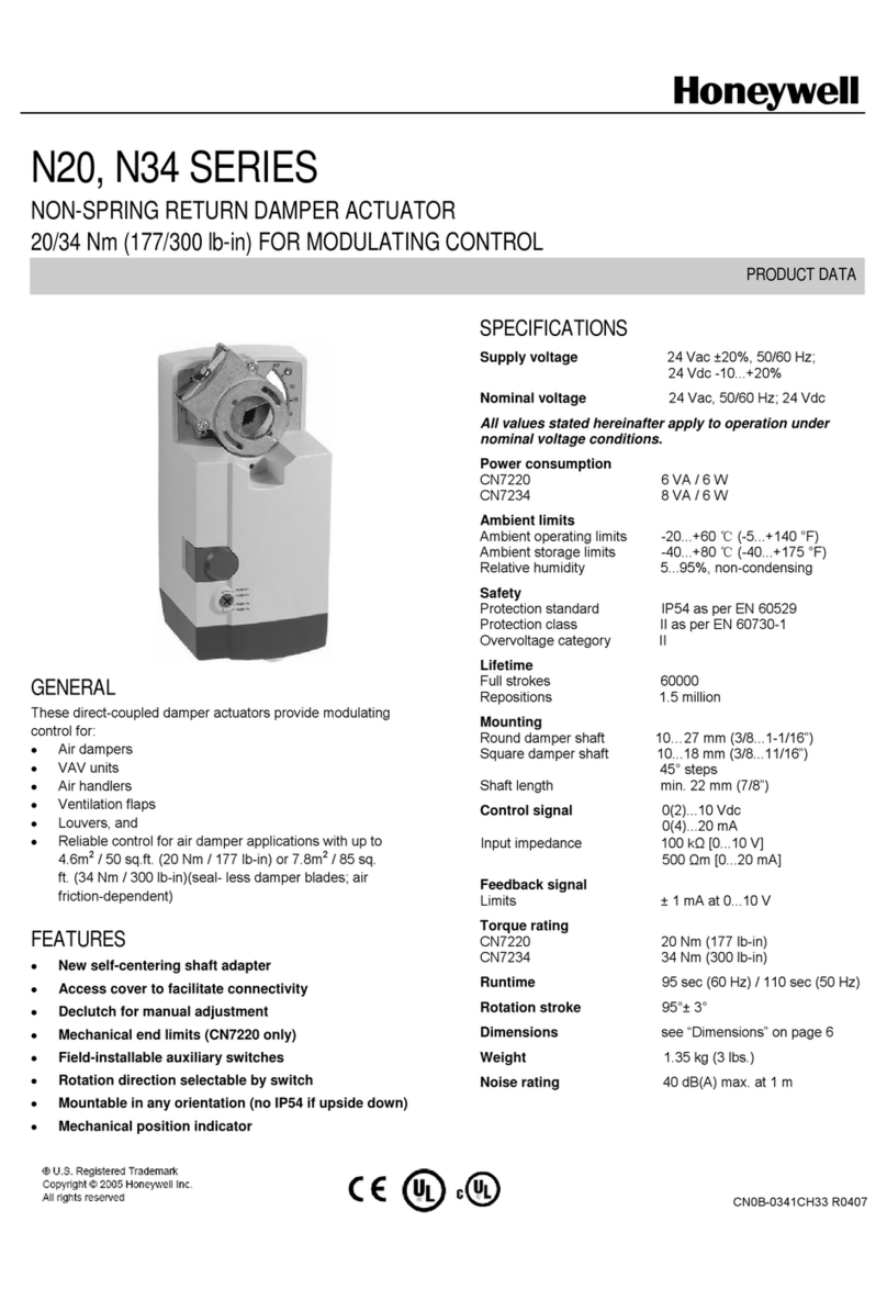
Honeywell 5 Nm Series Product data

Lilin
Lilin PIH-931D instruction manual
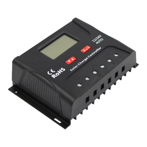
Sun21
Sun21 CCS Series user manual

thomann
thomann STAIRVILLE DMX-Master MK II ENC user manual
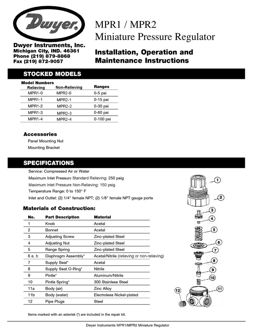
Dwyer Instruments
Dwyer Instruments MPR1 Installation, operation and maintenance instructions
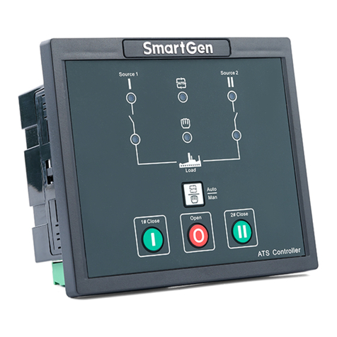
Smartgen
Smartgen HAT530N user manual
