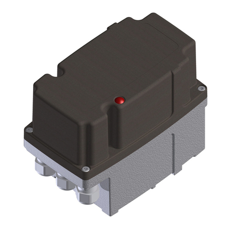
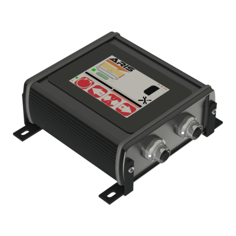
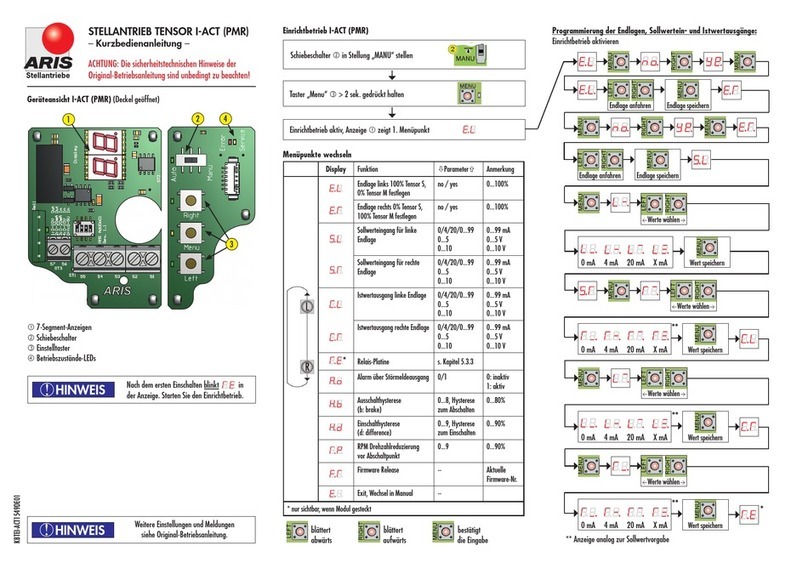
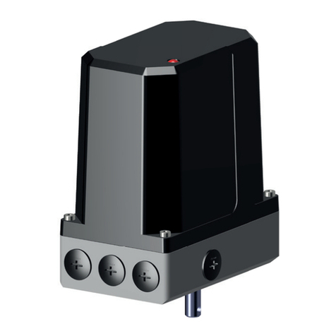
ARIS Tensor Zone 2/22 User manual

Original declaration of
incorporation with manual for
ARIS actuator Tensor
Tensor
Tensor+ (Option)
Tensor+ Zone 2/22 (Option)
TE1737EN01
Stellantriebe

Table of contents
1.Identication ................................................................................................................................................................3
1.1 Nameplate......................................................................................................................................................................................................................... 3
1.2 Guidelines and standards ................................................................................................................................................................................................... 4
2.Safety information ........................................................................................................................................................4
2.1 Warnings........................................................................................................................................................................................................................... 4
2.2 General safety advices ....................................................................................................................................................................................................... 4
3.Technical specication....................................................................................................................................................5
3.1 Functions and application areas (Intended use)................................................................................................................................................................... 5
3.2 Safe and accurate use ........................................................................................................................................................................................................ 5
3.3 Dimensions........................................................................................................................................................................................................................ 6
3.4 Performance data.............................................................................................................................................................................................................. 9
3.5 Expected lifespan and intended disposal ........................................................................................................................................................................... 10
4.Actuator setup for utilization .......................................................................................................................................10
4.1 Transport, (temporary) storage and downtimes................................................................................................................................................................. 10
4.2 Packaging ....................................................................................................................................................................................................................... 10
4.3 Safe disposal of packaging............................................................................................................................................................................................... 10
4.4 Installation and mounting ................................................................................................................................................................................................ 10
4.5 Initial operation............................................................................................................................................................................................................... 12
5.Actuator operation without controller and display module (Standard) .............................................................................13
5.1 Programming the end positions (Setup mode) without option modules............................................................................................................................... 14
6.Operations with modules and extras............................................................................................................................15
6.1 LED display module.......................................................................................................................................................................................................... 16
6.2 Potentiometer (electronic via additional board)................................................................................................................................................................. 16
6.3 Additional auxiliary switches S1-S4 (add-on board).......................................................................................................................................................... 18
6.4 Programming of the switching points without 7-segment display........................................................................................................................................ 19
6.5 Programming of the switching points with 7-segment display............................................................................................................................................. 20
7.Operation of actuators with microprocessor controller I-ACT (PMR)................................................................................21
7.1 Wiring diagram and pin conguration .............................................................................................................................................................................. 21
7.2 Congure controller connection ........................................................................................................................................................................................ 22
7.3 Operation and display elements........................................................................................................................................................................................ 23
8.Operation of the I-ACT (PMR), Current output ..............................................................................................................24
8.1 Automatic and hand mode................................................................................................................................................................................................ 24
8.2 Setup mode I-ACT (PMR).................................................................................................................................................................................................. 25
9.Operation of the actuator with current output...............................................................................................................32
9.1 Circuit diagram and pin assignment.................................................................................................................................................................................. 32
9.2 Funktion kongurieren .................................................................................................................................................................................................... 33
9.3 Operation........................................................................................................................................................................................................................ 33
10.Additional advices concerning the intendet use in potentially explosive atmospheres of the zone 2 and 22 (Option) ........35
10.1 Nameplate....................................................................................................................................................................................................................... 35
10.2 Guidelines and standards ................................................................................................................................................................................................. 36
10.3 Technical specications..................................................................................................................................................................................................... 36
10.4 Performance data............................................................................................................................................................................................................ 37
11.Additional options.....................................................................................................................................................38
11.1 Internal manual override (mechanical)............................................................................................................................................................................. 38
11.2 Option Handwheel ........................................................................................................................................................................................................... 38
12.Parameter RESET ......................................................................................................................................................39
13.Required customer information...................................................................................................................................39
13.1 Troubleshooting and repair............................................................................................................................................................................................... 39
13.2 Mains lter...................................................................................................................................................................................................................... 41
14.Maintenance .............................................................................................................................................................41
14.1 Service ............................................................................................................................................................................................................................ 41
14.2 Accessories....................................................................................................................................................................................................................... 41
14.3 Spare parts...................................................................................................................................................................................................................... 41

3Tensor
1. Identication
This manual is valid for:
Description: Electric actuator
Type: Tensor
Serial no.: YYWW-xxxxx-01001 ff.
1.1 Nameplate
Serial number (YYWW= year of manufacture+week)
Actuator type
Voltage/Frequency (DC as an option)
Actuating time/Torque/Power consumption
Ambient temperature/Protection class
ARIS Stellantriebe GmbH
Rotter Viehtrift 9
D-53842 Troisdorf
www.stellantriebe.de
SNr: YYWW-XXXXX-01001
Typ: Tensor
85...265 V AC, 50/60 Hz
60s/90°, 15 Nm, 20 VA
UT -15°C/+60°C IP65
Made in
Germany
Stellantriebe

4Tensor
1.2 Guidelines and standards
ARIS actuators are partly completed machinery according to directive 2006/42/EC.
Further applicable EC directives: EMC Directive 2014/30/EC DIN EN 61000-3-3
DIN EN 61000-6-2
DIN EN 61000-6-3
DIN EN 61000-6-4
DIN EN 55011
Applied harmonized standards: LVD Directive 2014/35/EC DIN EN 61010-1:2011-07
MachDir 2006/42/EC DIN EN 12100:2011-03
Protection class by housing (IP-Code) Protection class testing DIN EN 60529:1991
EMC considerations of the overall system and system perturbations and their ght have
to be treated by the system manufacturer or system operator. The wiring of the actuator
should be carried out in accordance with DIN EN 60204-1.
2. Safety information
2.1 Warnings
Installation and initial operation only by certied experts according to the manual.
Observe the signicance of the following symbol and note explanations. They are subdevided in security levels and classied
according to ISO 3864-2.
DANGER indicates a hazard with a high risk degree, which, if not avoided, causes death or
heavy injuries.
WARNING indicates a hazard with a medium risk degree, which, if not avoided, can cause
death or heavy injuries.
CAUTION indicates a hazard with a low risk degree, which, if not avoided, can cause slight
or moderate injuries.
Indicates general advices, useful hints and work recommendations, which don´t have
inuence on the safety and health of the staff.
2.2 General safety advices
The actuator components are conform to the state of the art and apply as generally safe at the time they are shipped.
This manual serves as basis to install and operate ARIS actuators safety conform. All persons working with or on ARIS actuators
must observe this manual and especially its safety advices.
• This manual has to be kept at the operating place at any time.
• Read the manual carefully prior to installation and initial operation.
While operation of electronic devices certain parts are obligatory under hazardous voltage.
DANGER
ADVICE
!
CAUTION
WARNING
ADVICE
!
ADVICE
!
WARNING

5Tensor
• Working on electric appliances or equipment is only allowed for electrically qualied persons or other instructed persons
under guidance and custody of an electrically qualied person according to the electro-technical regulations.
• Observe all safety and accident prevention regulations while installing, operating and testing any electrical appliances or
machinery.
• Prior to all installation or regular work on the actuator make sure to switch off all connected machinery/appliances.
3. Technical specication
3.1 Functions and application areas (Intended use)
ARIS actuators are exclusively designed for industrial use. ARIS actuators are utilized for operating regulating and shut-off appli-
ances (valves, ball valves, taps, slide valves, dosing pumps, etc.).
ARIS actuators may not be used for:
• Temperatures below or above the specied data
• Underground environments
• Near open res
• Under water
3.2 Safe and accurate use
ARIS actuators are factory checked prior to delivery. The nal functional testing must be performed within the total system by
qualied technical personnel.
The ARIS company assumes no liability for any direct or indirect damage arising from
• an insufcient test period of the actuator in the total system,
• an improper utilization of the actuator,
• a further utilization after an error was detected.
Perform controls on a regular basis during the operation. Pay particular attention to:
• intended utilization of the actuator (Chapter 3.1);
• unusual sounds, severe vibrations or increased temperatures;
• examine the correct tightening torque and impermeability of xing screws, cable entries, cable glands and sealing plugs;
• the condition of the electrical lines.
Should malfunctions arise, you have to stop the actuator and remedy the malfunction.
All persons who do the installation, commissioning and setting must
• be specially trained and qualied;
• be mentally and physically capable;
• observe the operating instructions.
• Valves, levers and connecting rods are moving during actuator operation.
• Check for proper function of all emergency equipment on your machinery/system.
• Check for proper function of the actuator and operated valves after completion of all installation work.
• Never work with or operate a faulty actuator.

6Tensor
3.3 Dimensions Tensor S
F05 Ø50
F03 Ø36
50
65
M6x9
M6x9
M5x9
2525
60
63
86
153
11
Ø20 4kt SW11
ISO shaft
inner 4-square
(Option)
12
40
6
Ø 5
Round shaft
with cross hole
(Standard)
40
16
4
3
Round shaft
with feather key
(Option)
30
25
Ø10
D-shape
(Option)
12
8
*Option metal cover (Tensor+) = 70 mm
*
*

7Tensor
Tensor M
M6x11
M6x11
F05 Ø50
50
65
25
25
153
86 40 60
63
82
14
4kt SW14
ISO shaft
inner 4-square
(Option)
40
Round shaft
with cross hole
(Standard)
40
L
P
3
Round shaft
with feather key
(Option)
D
D
6
B
T
Type D B L P T
30 to 40 Nm 12 5 16 4 2.5
50 to 60 Nm 14 6 22 5 3 Special shafts upon request
*Option metal cover (Tensor+) = 70 mm
*

8Tensor
Kabelveschraubungen optional
(Standard=Blindstopfen)
45
6
3
22
ø20
t=3,5
Welle rund mit
Passfedernut
(Option)
Welle rund mit
Querbohrung
(Standard)
21,6
4kt SW17
Innenvierkant
(Option)
63 60
63
86
153
ø
8
45
20ø
10
25
25
M8x12
F07 ø70
42
*Option metal cover (Tensor+) = 70 mm
*
Tensor L
Option metal lid
inner 4-square
cable gland optional
(standard=blind plug)
round shaft with
cross hole
(standard)
round shaft with
feather key
(option)

9Tensor
3.4 Performance data
3.4.1 Actuator specications
3.4.2 Specications I-ACT (PMR)
Protection class IP65 (IP 66/IP 67 Option)
Motor • Supply: 85...265 V AC (50/60 Hz) / 24…48 V DC
• Protection: Primary: 2A Tr
• Control: BLDC
• 50/60Hz ±5%, 100% ED
• Isolation class E acc. to DIN EN 60085
Connection 3 cable entries M16x1.5 (customer provided)
Path cutoff Digital via magnet sensor
Ambient temperature -15 °C up to +60 °C (other temperature range optional)
Installation position Arbitrary
Potentiometer (Option) Electronic
Travel 28°…100 revolutions
Function group ash controller, DSP functions
System resolution 12 bit
Set value input Current input max. 0...20 mA, burden 250 W
Voltage input adjustable 0...5 V or 0...10 V
Limited protection against overload and reverse polarity
Actual value transducer Magnetic position sensor on basic board
Actual value output 4...20 mA, 0...20 mA, galvanically isolated
Burden max. 500 Ω, Output stroke max. 10 V
Burden 250 Ω, Output stroke 0...5 V
Operation 3 buttons: Left / MENU / Right
1 switch: AUTO / MANU
Status display via two 7-segment displays

10 Tensor
3.5 Expected lifespan and intended disposal
ARIS actuators have an expected lifespan of several years, depending on their utilization and application. No longer usable actua-
tors must not be dismantled as a whole, but separately recycled in parts divided by their materials. Non-recyclable components
must be disposed according to national disposal regulations.
4. Actuator setup for utilization
4.1 Transport, (temporary) storage and downtimes
Use the factory packaging for transport to the installation point.
Replace a damaged original packaging by a new solid packaging.
• Actuators with attached valves: Attach lifting gear only on the valve and NEVER on the actuator;
• Do not use ARIS actuators as a climbing or support aid;
• ARIS actuators must not operate in unsecured lifting operations without additional applications
Damage by wrong storage
• Store in well-ventilated rooms;
• Protection against possible ground humidity (shelf storage).
• Add moisture-absorbing agents to the actuator during longer periods of storage.
• Protect the actuators from dirt and dust.
• Take measures for prevention of condensation (e.g. at temperature uctuations).
4.2 Packaging
ARIS actuators are protected by special cardboard packaging at delivery.
4.3 Safe disposal of packaging
Additionally necessary packaging is made by easily separable packaging materials and can be recycled individually:
• Wood
• Cardboard
• Paper
• Plastics
4.4 Installation and mounting
• Inspect the actuator for damages prior to installation;
• the screw-in depth of connecting thread holes must not exceed 9 mm;
• check leak tightness of cable glands and blank plugs prior to initial operation;
• tighten the cover screws evenly (max. 1.2 Nm);
• do not operate before limit switches have been adjusted;
• protect the actuator against climatic inuences (e.g. by a protective cover);
• do not expose the actuator to hard shocks (e.g. by dropping);
ADVICE
!

11Tensor
• do not attach ropes, hooks or the like to the actuator;
• permanent overload and blocking leads to actuator damages;
• use only ARIS original spare parts.
Consider prior to attachment of couplings:
• Do not turn actuator shafts by force;
• actuator and valve shafts must run centric.
For all actuators observe the following advices:
The initial operation of the actuator is only permitted with orderly closed cover and closed cable entries. Use only cable glands
which are appropriate for the respective protection class.
• Cable entries
Ensure that all cable entries are closed properly during storage, installation and initial operation.
Use only cables which are suitable for the diameter of the cable entries.
• Cover assembly
During the cover assembly make sure that the cover ts correctly.
The cover must not show any damages on the joint surface.
Tighten cover screws evenly (max. 1.2 Nm).
No additional bores are allowed in the housing and the cover.
CAUTION

12 Tensor
4.5 Initial operation
4.5.1 Electrical connection
Hazardous voltage: Possible stroke!
• The initial operation must be carried out only by experts!
• De-energize the actuator before opening.
• Observe the appropriate regulations during electrical installation and initial
operation.
Connect the actuator as follows (wiring diagram see chapter 4.5.2):
• Connect the ground wire of the electric supply to the appropriate protective earth terminal.
• Always refer to the wiring diagram located inside the actuator.
Check prior to initial switch on:
• Is the actuator undamaged on the outside?
• Is the mechanical connection correct?
• Has the electrical connection been made regularly?
• Check if current type, voltage and frequency match with the motor data (see nameplate on cover and inside the actuator).
• Insert suitable cable glands for the connection line.
• Observe the wiring diagram inside the cover.
• Use separate (shielded) wires for low voltages.
• Set up limit switches prior to initial operation.
4.5.2 Wiring diagram
Connection 85...265 V AC
N Neutral conductor
L Phase / Supply 85 ... 265 V AC
2 Control connection > left-turning
3 Control connection > right-turning
Connect the ground wire to the housing.
–/+ Connection 24…48 V DC
2 Control connection > left-turning
3 Control connection > right-turning
WARNING
Version 24/48 V DC
M
M

13Tensor
The control terminals only have a function if the tensor electronics are operated without the
controller module I-ACT (PMR).
The drive must be permanently energized, otherwise the holding torque is not available!
5. Actuator operation without controller and display module (Standard)
5.1 Operation
5.1.1 Buttons and switches
The buttons (1) are marked with
LEFT [L]
MENU [M]
RIGHT [R]
Switch (2) changes between automatic and manual mode.
In MANU position the setup operation can be turned on
from manual mode by keystroke.
5.1.2 LED displays
The LEDs on the operation module show information by
ashing or blinking.
ADVICE
!
CAUTION
On/Off
Blinking

14 Tensor
In case of loss of the mains voltage the MENU LED turns off. After saving the sensor
position all LED light until the nal loss of the operating voltage. The drive does only have
a mechanical holding torque.
5.2 Programming the end positions (Setup mode) without option modules
1. In manual mode, press the MENU button for >5s the menu LED ashes 2x. Now the setup mode is active, the drive can
now be moved even over the pre-programmed limits.
2. Move the actuator to the left end position using the LEFT button. Hold buttons MENU and LEFT at once. Left LED is
blinking. Hold buttons until the LED ashes permanently the left end position is now saved.
3. Move the actuator to the right end position using the RIGHT button. Hold buttons MENU and RIGHT at once. Right LED is
blinking. Hold buttons until the LED ashes permanently the right end position is now saved.
• Quit the programming mode by switching to AUTO mode or by cutting the supply voltage.
• Now the actuator moves only between the programmed end positions.
Left and right end position can be reversed, the allocation of the directions of rotation of
the inputs 2/3 and the switch LI/RE does not change as a result.
ADVICE
!
ADVICE
!
Down shaft rotates left
End position reached or override
Supply voltage ON
Setup mode active
Down shaft rotates right
End position reached or override
ON: Automatic active
OFF: Hand mode active
Current limit active at actuator LI/RE
no error
Holding current active at motor STOP
Sensor error
Motor error
Status changing every second
Microcontroller in function and OK
ON
2x blink
ON
2x blink
ON
2x blink
ON/OFF
ON
OFF
1x blink
4x blink
5x blink
ON/OFF
Meaning

15Tensor
6. Operations with modules and extras
Menü Funktion Parameter Anmerkung
EL
Endlage links no / yes 0…100%
ER Endlage rechts no / yes 0…100%
SL Sollwerteingang links
SR Sollwerteingang rechts
CL Istwertausgang links
CR Istwertausgang rechts
db Drahtbrucherkennung OF,St, oP, Po, cL
Off/Stop/Open/Clo
se/Position
PL
Poti links
PR
Poti rechts
RE Relais-Platine s.Kapitel 5.3.3
Ao Alarm über
Störmeldeausgang
0/1/2 1,2 aktiv; 0 inaktiv
Ad
Meldung
Regelabweichung
0:1..9 1%...9%
FI
Netzfilter 0…5 Aus…90%
Hb
Ausschalthysterese
(b:brake)
0…8, Hysterese
zum Abschalten
0…80%
Hd
Einhalthysterese
(d:difference)
0…9; Hysterese
zum Einschalten
0…90%
RP
RPM Drehzahlreduzierung 0…9 0…90%
SC
Stall Count 1…5 Startversuche
bL
Block Detection 0: 1…9 0=OFF, 1…9%
FR Firmware Revision Zeigt die Firmware
E
Exit
0/4/20/0…99
0…5
0…10
0…99 mA 0…5
V 0…10V
Übersicht Zuordnung der Tensor Menüpunkte
zu den jeweiligen AddOn Boards
AddOn
PMR
AddOn
Stromausgang
AddOn
LED
AddOn
Potentiometer
Overview allocation of the tensor menu items to the particular AddOn Boards
power output
Menu Function Remarks
end position left
end position right
set value input left
set value input right
actual value output left
actual value output right
wire break detection
Poti left
Poti right
relay board
alarm via
fault message output
message
control deviation
Main lter
switch off hysteresis
switch on hysteresis
speed drop
shows rmware
staring attempts
OFF
1,2 active; 0 inactive
Chapter
hysteresis
hysteresis
to switch off
to switch on
0...99 mA 0...5V
0...10V
Off/Stop/Open/
Close/Position

16 Tensor
6.1 LED display module
The LED display module simplies the setup of the actuator via a clear presentation of the
menu items in the double-digit 7-segment display.
6.2 Potentiometer (electronic via additional board)
Connection conguration
Use only shielded wires
18 GND Poti
19 Output Poti 0...100% (Wiper, output impedance 1 kΩ)
20 +Ub Poti 5...24 V DC
56, 57 Fault message output (potential free closer max. 200 V/0.5 A)
Actual value output of the potentiometer end position
The actual value has to be determined for both stop positions.
• Choose menu item „PL“ for programming the left end position or „PR“ for the right end position and conrm with button
[M]. The Display indicates a conrmation dialogue.
PL
Pt
• Set the desired value with [R] or [L]. The Display indicates a conrmation dialogue.
L_.0% Lw.10% Ln.90% L_.100% L≡. free values
• Save the value with the button [M], this will activate the next menu item automatically.
The potentiometer module has to be evaluated in the voltage division circuit in general.
U+
U–
UM
18
19
20 5–24 V DC
max. 0,5 A
5–24 V
DC
57 56
ADVICE
!

17Tensor
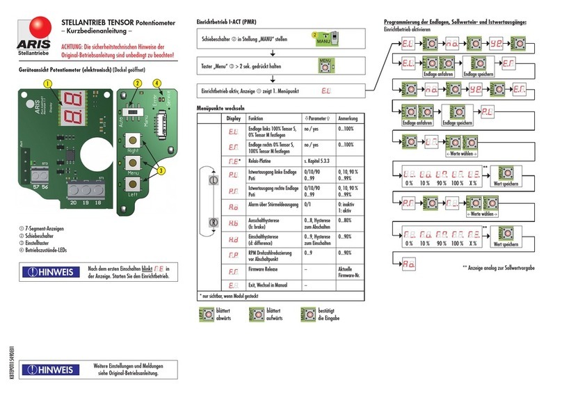
Set-up operation potentiometer
Set slide switch in position „MANU“
Push Button „Menu“ for > 2 sek.
Set-up operation active, display indicates 1. Menu item
Approach end position Save end position
Select values
0 % 10 % 90 % 100 % X % Save value
Select values
Save value
Programming the end position, setpoint input and actual value output:
** Display analog to setpoint entry
**
**
0 % 10 % 90 % 100 % X %
Set-up operation nished. Exit through menu item EExit

18 Tensor
6.3 Additional auxiliary switches S1-S4
(add-on board)
The additional board ZW provides outputs for up to four additional
bistable relays with preservation of the switching status in the deener-
gized condition, to be freely programmed.
Switching points
It can be dened for each relay a left and right switching point.
While moving from LEFT to RIGHT applies to the transitions:
- SPL left switching point changes from OFF to ON
- SPR right switching point changes from ON to OFF
Example switching pattern
By dening and positioning of these two switching points different shift pattern can be freely dened.
Example switching pattern inverted
6 7 89 10 11 12 13 14 15 16 17
LN 23
M
85...265 V (AC)
18 19 20
Option
Option
S2S1 S3 S4
Poti
left end position
left end position
right end position
right end position
OPEN
OPEN
CLOSED
CLOSED

19Tensor
If no switching point dened, the corresponding relay is not switching. When turning on the
power supply all switching points are checked and the relays are preset or possibly switched
according to the current sensor position.
Minimum width of the switching point
Both switching points must be different and must have a minimum distance. If they are programmed too close to each other, the
switching points are placed with a minimum width (1/512 of the current sensor resolution) around the current position.
Sequential output
The relays are switched sequentially to the current reduction, i.e. if several relays are programmed on one and the same switching
position, they are switched on or off in succession of REL1 to REL4 , the delay here is max. two program cycles (about 100ms).
Forced circuit
In order to detect even short switching points with fast angle changes each position crossing is stored and then processed and
switched sequentially. Here is the minimum switch-on or -off time one cycle (about 50ms). This may lead to a short "tracking" of
the switching points.
6.4 Programming of the switching points without 7-segment display
1) Choose programming mode
• In hand mode push [MENU]-button > 2s The menu LED is blinking 2x (see chapter 5.1.2)
• Push [MENU]-button again >4s The menu LED is blinking 4x
2) Choose relay
The current selected relays is now indicated via the appropriate fast blinking LED. Select the desired relays with buttons [R] / [L].
Conrm with [MENU].
3) Dene/delete switching points
Now the switching points can be dened.
• Set the desired position via buttons [L] / [R], then save:
[MENU] + [L]: Save left switching position
[MENU] + [R]: Save right switching position
[L] + [R]: Delete both switching positions. Hold both buttons at once, until the appropriate LED (L and/or R)
blinks fast and then permanently ashes.
Display of LEDs on the relay board:
Selected relays: - slowly blinking ca. 1x/sec.: no switching position dened
- 1x ash: 1 switching position dened
- 2x ash: 2 switching positions dened
Not selected relays: - all showing the actual status of the selected relays (ON / OFF)
To ensure reliable switching even when driving over an end position, it can be run over by
about 10° by pressing the L / R button.
ADVICE
!
ADVICE
!

20 Tensor
4) Select other relays
• Button [M] > push 2 seconds further see item 2) or 5)
5) Exit programming menu
• Switch to AUTO mode.
During loss of supply voltage the current switching states remain unchanged. After switching
on again the relay states will be determined and set by means of the current sensor position.
6.5 Programming of the switching points with 7-segment display
1) Select programming mode
• In hand mode push MENU button > 2s the display shows „EL“
• Select menu item RE via button [R] and conrm with [Menu].
2) Select relays
Select the desired relays with buttons [R] / [L]. The selected relays is shown in the display.
The additional fth menu item E (EXIT) can be selected.
Conrm with [Menu].
3) Dene/delete switching points
Now the switching points can be dened.
• Set the desired position via buttons L / R, then save/delete:
The actual position is shown (0..100%).
By activating the buttons, the appropriate commands are issued:
• [MENU] + [L] SL (Save Left) Save left switching point
• [MENU] + [R] St (Save Right) Save right switching point
• [L] + [R] dE (Delete)
• [MENU] E(EXIT)
4) Select other relays
• Push button [M] > 2 seconds further see item 2) or 5)
5) Exit programming menu
• Select menu item E (EXIT) and conrm with [MENU]
ADVICE
!
This manual suits for next models
1
Table of contents
Other ARIS Controllers manuals

ARIS
ARIS TENSOR User manual

ARIS
ARIS Tensor2 User manual

ARIS
ARIS TENSOR Installation guide

ARIS
ARIS LINEARIS User manual

ARIS
ARIS SCU5 User manual

ARIS
ARIS Nano+ User manual

ARIS
ARIS Classic Series User manual

ARIS
ARIS TENSOR I-ACT (PMR) Installation guide

ARIS
ARIS PD Technical document

ARIS
ARIS TENSOR Installation guide