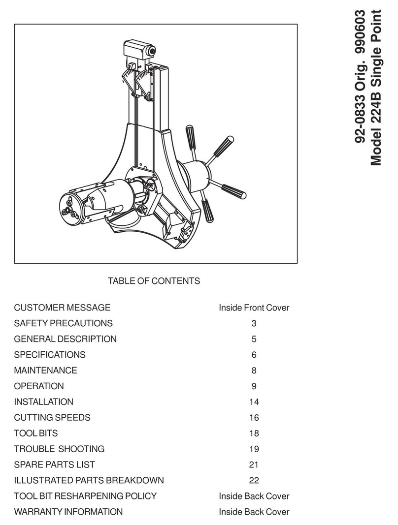
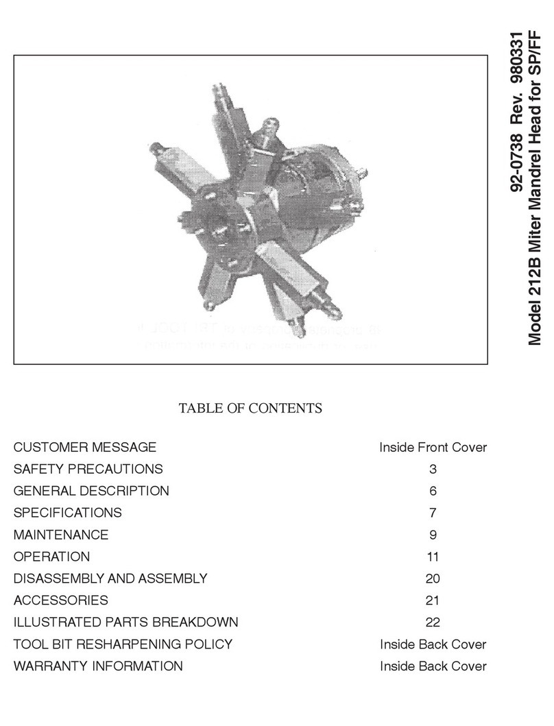
TRI tool SUREFIRE 4 User manual

Oper ation
Manual
92-1983 Rev. 221103
Model SUREFIRE 4

ABOUT TRI TOOL TECHNOLOGIES
At Tri Tool, we are committed to your success through
relentless innovation and powerful partnership. We
insist on developing tools and equipment that exceed
your expectations of performance, precision, safety, and
durability. As a full-service engineering rm, we are here to
support you every step of the way.
For more information on engineered solutions, products,
and trainings, visit tritool.com or contact our engineers at
+1(916) 288-6100.
Table of Contents
Tri Tool Inc Warranty..........................................2
Tool Bit Resharpening Policy ...................................3
About the Manual ............................................4
Safety Precautions ...........................................6
General Description ..........................................8
Training Level ...............................................9
Specications ..............................................10
Maintenance ...............................................13
Operation .................................................14
Machining Operation.........................................17
Cutting Speeds and Feeds ....................................19
SUREFIRE 4 Pad Kits .......................................20
Tool Bits ..................................................22
Trouble Shooting............................................25
Illustrated Parts Breakdown ...................................26
92-1983 Rev. 221103
Model SUREFIRE 4

TRI TOOL INC.
92-1983 Rev. 221103
2
TRI TOOL INC. Warranty
LIMITED WARRANTY: All products manufactured by Seller are warranted to be free from
defects in materials and workmanship under normal use. The period of this warranty shall
be three years from the date of shipment for all products, except for welding and Non-
Standard Products which shall be one year from the date of shipment. The Buyer shall
bear all shipping, packing and insurance costs and all other costs to and from a designated
repair service center. All return goods must be authorized in advance and communicated
upon issuance of a Return Material Authorization (RMA) by Seller. The product will be
returned to the Seller accompanied by a RMA number and associated paperwork, freight
prepaid and billed to the Buyer. This warranty is not transferable and will not apply to tool
bits or other consumables, or to any Goods to have been (i) mishandled, misused, abused
or damaged by Buyer or any third party; (ii) altered without the express permission in writing
by Seller, (iii) repaired by a party other than Seller without Seller’s prior written approval;
or (iv) improperly stored, installed, operated, or maintained in a manner inconsistent with
Seller’s instructions. This warranty does not apply to defects attributed to (i) normal wear
and tear or (ii) failure to comply with Seller’s safety warnings.
No warranty for any parts or other supplies provided to seller by buyer, whether or not they
are incorporated into goods. Goods supplied by seller which are designed or manufactured
by a third party are subject strictly to the third party’s warranty for those goods. Seller
makes no warranty and disclaims all statutory or implied warranties for these goods,
including the implied warranties of merchantability, freedom from patent infringement and
tness for a particular purpose.
Neither this warranty nor any other warranty, expressed or implied, including implied
warranties of mechanical ability, tness for a particular use, or merchantability, shall extend
beyond the warranty period. No responsibility is assumed for any incidental or consequential
damages. Some states do not allow limitations on how long an implied warranty lasts and
some states do not allow the exclusion or limitations incidental or consequential damages,
so the above limitation of exclusion does not apply to all Buyers. This warranty gives the
Buyer specic legal rights. Other rights vary from state to state.
Warranty Claims and Remedies
Buyer must promptly notify Seller in writing during the applicable warranty period, of
any defective Goods covered by Seller’s warranties under the Limited Warranty section
herein, and no later than fteen (15) calendar days after discovery of the defect. Seller
has no obligation to honor any warranty claim made after the expiration of the warranty
period. However, despite the expiration of the warranty period, Seller, at its reasonable
discretion, may accept warranty claims submitted up to fteen (15) calendar days after
the expiration of the warranty period provided that Buyer provides Seller with credible and
persuasive documentary evidence that the defect was discovered during the warranty
period. No warranty claims submitted after this fteen (15) day calendar period will be
considered by Seller.

Model SUREFIRE 4
92-1983 Rev. 221103 3
If the defect claimed by Buyer cannot be reproduced or otherwise veried by Seller, the
Goods will be returned to Buyer unmodied at Buyer’s expense.
The warranty period for repaired or replaced Goods shall be (i) ninety (90) days or (ii) the
unexpired portion of the original warranty period. Under no circumstances is Seller liable for
recall, retrieval, removal, dismantling, re-installation, redeployment, or re-commissioning of
any defective Goods or any costs associated therewith.
Tool Bit Resharpening Policy
Buyer’s notice of a defective Goods must identify the specic Goods affected, and the
nature of the defect. It is required when returning the defective Goods, that it is suitably
packed, fully insured, and transportation and insurance prepaid in accordance with
instructions issued by Seller. Seller, at its sole option, will either repair or replace any
Goods authorized for return to Seller. Such repair, replacement, or credit shall be Buyer’s
sole remedy for defective Goods. Buyer must promptly provide Seller with all information
requested regarding the identied defect.
Buyer is required to check all tool bits prior to returning and ensure they are packaged well
for shipment. The price structure is available from the Seller’s sales coordinator. Seller
cannot resharpen badly gouged, chipped, or broken tool bits. Seller will return tool bits that
are not suitable for resharpening with the tool bits that were resharpened upon Buyer’s
request. Buyer is responsible for all shipping charges to and from Seller.

TRI TOOL INC.
92-1983 Rev. 221103
4
1. ABOUT THE MANUAL
ORIGINAL INSTRUCTIONS
Copyright
©Copyright Tri Tool Inc. Proprietary property of Tri Tool Inc. No reproduction, use, or
duplication of the information shown hereon is permitted without the express written consent
of Tri Tool Inc.
Disclaimer
The instructions and descriptions in this manual were accurate when the manual was
written. However, the information in the manual is subject to change without notice. Check
for updated information before you start any job. The Tri Tool Inc. web site has the most
current information.
Do not operate or work on this equipment unless you have read and understood the
instructions in this Manual. Failure to follow the instructions or follow the safety instructions
could result in serious injury or death. This manual describes conditions and hazards
that are common and anticipated during equipment operation. No manual can address all
conditions which may occur.
Safety Symbols
The manual may contain one or more safety symbols. These symbols and the associated
text warn you of potentially hazardous conditions. Examples of the safety symbols and the
associated text follow:
DANGER
DANGER: Indicates a hazardous situation that, if not avoided, will result in serious
injury or death.
WARNING
WARNING: Indicates a hazardous situation that, if not avoided, could result in serious
injury or death.
CAUTION
CAUTION: Indicates a hazardous situation that, if not avoided, could result in minor or
moderate injury, or cause property damage.

Model SUREFIRE 4
92-1983 Rev. 221103 5
GLASSES
SAFETY GLASSES: Indicates a hazardous situation that requires the use
of safety glasses.
HOT SURFACE
HOT SURFACE: Indicates a hazardous situation that hot
surfaces may be present.
SHOCK HAZARD
ARC FLASH & SHOCK HAZARD: High voltage. Entry by authorized
personnel only. Appropriate PPE and tools required when working on this
equipment.
GLOVES
GLOVES: Indicates a hazardous situation that requires glasses.
READ MANUAL
READ MANUAL: Read manual before use, refer to manual for Tri Tool
machine being used.
DISCONNECT
FROM POWER
DISCONNECT FROM POWER: Disconnect main plug from electrical outlet
before performing all maintenance.

TRI TOOL INC.
92-1983 Rev. 221103
6
2. SAFETY PRECAUTIONS
In General
Use standard safety equipment such as: hard hats, safety shoes, safety harnesses,
protective clothes, and other safety devices when appropriate.
Operate this tool only in accordance with specic operating instructions.
WARNING
WARNING: Do not override the dead-man switch on the power unit. Locking down,
obstructing, or in any way defeating the dead-man switch on the power drive unit may
result in serious injury.
Personal Protective Equipment
Use standard safety equipment such as: hard hats, safety shoes, safety harnesses,
protective clothes, and other safety devices when appropriate.
Wear safety glasses.
Do not wear loose clothing or jewelry.
Wear nonskid footwear.
Put long hair in a cap or a net to make sure hair does not get tangled in equipment.
Personnel
Only personnel who are trained or are being trained may operate the equipment.
Keep the operation manual available where the equipment is used.
The operator must read the operation manual before using the equipment.
The equipment must be operated in accordance with the manual information.
The operator must follow the safety precautions in this manual and good engineering
practices to reduce the risk of injury.
Before using the equipment, the operator must ensure that all safety messages on the
equipment are legible.
Work Area
Keep the work area clean.
Keep the area well lit.
Keep items such as electrical cords, cables, rags, rigging straps, away from rotating
equipment.

Model SUREFIRE 4
92-1983 Rev. 221103 7
Do not use power-cutting tools in the presence of ammable liquids and gases.
Do not let visitors or untrained personnel near tools that are in use.
Ensure all observers wear eye protection.
Keep proper footing at all times.
Area Equipment
Secure the pipe with clamps, vises, chains or straps.
Ensure that both sides of the pipe at the cut site is fully supported so that the pipe will not
move after the cut is completed. Long lengths of pipe may be under load and the separation
of the pipe can release pressure. This pressure can cause both sides of the pipe to move.
Tool Care
Keep tools in good operating condition. Sharp tool bits perform better and are safer than dull
tool bits.
Do not use damaged tools. Always check your tools for damage especially if a tool has
malfunctioned, been dropped or hit, check it for damage.
Before you start operating the equipment, do no-load tests and feed function checks.
Tool Use
Use the right tool and tool bit for the job. Contact Tri Tool to help with your application.
Keep the tool bits fully engaged in the tool bit holders. Loose bits are sharp and can cause
cuts or punctures.
Disconnect power supply during setup and maintenance. Use all ‘Stop’ or Shut off’ features
available when changing or adjusting tool bits, maintaining the tool, or when the tool is not in
use.
Remove adjusting keys and wrenches before applying power to the equipment. Check the
tool before turning it on to make sure that all keys and wrenches have been removed.
Store tools properly. Disconnect tools from the power source, remove the tool bits, and store
in a safe place.

TRI TOOL INC.
92-1983 Rev. 221103
8
3. GENERAL DESCRIPTION
The SUREFIRE 4 Model is a portable full support ID mounting machine tool specically
designed for facing thin wall pipe weld end preparations
Pipe weld end preparations that meet all existing conventional codes including the more
stringent nuclear codes may be machined.
The SUREFIRE Pads secure the Model to pipe from sizes 2”- 4” schedules 5S-10S.
The SUREFIRE 4 accepts the reaction torque generated by the machining operations
through the mandrel.
No additional restraining devices are required.
Intended Use
This equipment is intended for professional use.
The equipment is intended to be used by a person with knowledge and experience in the
use of a machine of this type, without limitations in the physical abilities of the upper limbs
and without visual impairment.
The machine is intended to be used with the operator in the upright position and in a variety
of stances as required by the application.
Reasonably Foreseeable Misuse
Do not use the System on tools other than those explicitly specied by Tri Tool.
Do not force tools. Tools and tool bits function better and safer when used at the
recommended speeds.
Do not reach into rotating equipment.
Do not reach into the rotating head stock to remove chips, to make adjustments, or to check
the surface nish.
Handle chips with care. Chips have very sharp edges and are hot. Do not try to pull chips
apart with bare hands.

Model SUREFIRE 4
92-1983 Rev. 221103 9
4. TRAINING LEVELS
Operators
Operators must be familiar with industry standard practices and must have read all manuals
associated with the product, Operators may also be expected to do routine maintenance as
instructed in the user manual.
General Public/Bystanders
Those in the vicinity of the operation of the system must be aware of appropriate safety
precautions such, as Personal Protection Equipment (PPE) for the work environment.

TRI TOOL INC.
92-1983 Rev. 221103
10
5. SPECIFICATIONS
Clearance and Dimensions
8.82in
224.1mm
16.45in
417.9mm
7.03in
178.4mm
23.13in
587.4mm
In-Line
Feed
Cutting Head
(Travel 1.50" Max.)
Mandrel
4.00in
101.6mm
ROTATING DIA.
Surefire Pads
MODEL SHOWN WITH 4" SUREFIRE PADS
77-1865
K. LUONGO
5/12/2022
PE0072
77-1865
77-1865.SLDDRW
1:6
MODEL SUREFIRE 4
PR
PR
1
1 OF 1
COMPANY CONFIDENTIAL
PROPRIETARY PROPERTY OF TRI TOOL
NO REPRODUCTION,USE,OR DUPLICATION OF THE
DESIGNS SHOWN HEREON IS PERMITTED WITHOUT
EXPRESS WRITTEN CONSENT FROM TRI TOOL
3041 SUNRISE BLVD., RANCHO CORDOVA, CA 95742
COPYRIGHT TRI TOOL INC.
ISSUED
CHECKED
DRAWN
DATE
APPROVALS
CONTRACT NO.
DWG. NO.
DWG
FILE:
SOLIDWORKS
AVAILABLE
A
SIZE
SCALE
SHEET
REV.
DWG
NO.
SHT
REV.
ENVELOPE DRAWING
3041 SUNRISE BLVD.
RANCHO CORDOVA, CA 95742
WWW.TRITOOL.COM
(888) TRITOOL
Figure 1: Envelope Drawing

Model SUREFIRE 4
92-1983 Rev. 221103 11
Pipe Cutting Capacities
Basic Pipe Sizes (Schedules 5S & 10S to all sizes)
• 2” pipe
• 21/2” pipe
• 3” pipe
• 4” pipe
* Custom Surere pad sizes available on request
Wall Thickness Capacity (Limitations)
Wall thickness of schedules listed, .120” (3 mm) maximum, in the range listed can be
machined without limitations.
Duty Cycle
The Surere 4 with an electric motor (P/N 58-0147 or equivalent) duty cycle on high cutting
load applications (see above), is limited to 50% ‘On’ time with a maximum of ve (5) minutes
continuos ‘On’ time.
Material Cutting Capabilities
Mild steels, chrome steels, (Rc 35 max), stainless steel, copper-nickel alloys and aluminum
without limitations except size and wall thickness as specied. Inconel and some other high
temperature alloys may require special procedures as a function of wall thickness and type
of end preparations. Contact Tri Tool’s Engineering Department for details.
Weight
25 lbs (11.3 kg)
Drive System
Final Drive
Gear Driven 6:1 Gear Reduction
Cutting Head Speeds
Low Range 0-14 RPM
High Range 0-42 RPM

TRI TOOL INC.
92-1983 Rev. 221103
12
Power Requirements
Electric Drive Motor 110 VAC, 50/60 Hz, 9.6 A
220 VAC, 50/60 Hz, 5.7 A
Speed Control
On/Off Trigger control with Variable Speed.
Mounting
Manually actuated draw rod expands mandrel ramps and jaw blocks.
Feed
Manual-Feed Handle is in line at the back of the machine. Feed rate is .100” (2.5mm) per
revolution of the feed handle.
Maximum available feed travel is 1.50” (38.1 mm)

Model SUREFIRE 4
92-1983 Rev. 221103 13
6. MAINTENANCE
All components should be cleaned and coated with a light lm of oil prior to use.
Figure 2: Chip clean up
When the SUREFIRE 4 is operated in the vertical position, cutting head up, it should be
turned upside down and the chips and/or other debris removed after each bevel has been
completed.
Tool life may be severely shortened, unless chips and/or other debris that have been
deposited on the cutting head during the machining operations are removed.
Verify that there is adequate grease in the gear box. Gears and bearings are to be
lubricated using a lithium based grease.
Disassembly of a power unit voids warranty, except when performed by a TRI TOOL INC.
designated repair technician. A letter of designation is required.

TRI TOOL INC.
92-1983 Rev. 221103
14
7. OPERATION
General Comments
Read the operating instructions carefully before attempting to operate the SUREFIRE 4
Use eye protection at all times when operating the SUREFIRE 4
Installation
1. Select the recommended jaw blocks for the pipe size to be machined.
2. Gently slide the mandrel assembly into the SUREFIRE 4 until it comes to a stop
against the torque acceptance key.
3. Rotate the mandrel assembly as required to engage the torque acceptance key
of the SUREFIRE 4 with the slot in the mandrel shaft.
CAUTION
CAUTION: Since the mandrel shaft will contact the torque acceptance key before the
feed nut engages the mandrel shaft threads, do not force or allow the machine to im-
pact the lead threads of the feed nut with the lead threads of the mandrel.
Tool Bit
Mandrel
Assembly
Feed Handle
Draw Nut
Figure 3: Tool components
4. Rotate the feed handle clockwise to engage the feed nut with the thread on the
mandrel shaft.
5. The SUREFIRE 4 with the mandrel assembly installed can be mounted into the
pipe as one unit.

Model SUREFIRE 4
92-1983 Rev. 221103 15
Draw Nut
Pipe
SUREFIRE
Pads
Final Prep
Location
Mandrel Assembly
Figure 4: Tool installation
NOTE: In order to avoid cutting the ramps and/or jaw blocks during the machining
operation, the mandrel must be installed beyond the nal preparation location.
6. Tighten the draw nut to force the jaw blocks out to the inside diameter of the
pipe or tube.
7. Verify a clearance of 1/8” (3 mm) minimum between the tool bit and the pipe
face.
Feed Handle
Draw Nut
Tool Bit
1/8" (3 mm)
Clearance
Pipe
Mandrel
Clearance
Figure 5: Tool setup

TRI TOOL INC.
92-1983 Rev. 221103
16
8. Select the tool bit(s) required to machine the pipe to the conguration desired.
WARNING
WARNING: Use of dull or improperly designed tool bits or tool bits not manufactured by
Tri Tool Inc. may result in poor performance and may constitute abuse of the machine
and therefore voids the Tri Tool Inc. factory warranty.
9. When performing any multiple machining operation such as facing and beveling,
the facing tool bit should be installed as shown.
Cam Adjustment
Lock (On the Side)
Cutting Edge, Tool Bit,
Facing (Land)
Cutting Edge,
Tool Bit, Beveling
Cam Adjustment
Cutting Head
Figure 6: Multiple machining setup
10. Insert the tool bit(s) into the slot(s) in the cutting head.
CAUTION
CAUTION: The cutting edge of the tool bit(s) must be located on the radial centerline.
CAUTION
CAUTION: Ensure that no tool bit is installed backwards.
11. Make sure that there is a clearance between the tool bit(s) and the mandrel.
12. Tighten the setscrews to secure the tool bit in the tool bit slot.
13. Adjust the bevel tool bit radially to control the land width.
14. Adjust the cam to alter the width of the land with the facing tool bit.
15. Attach the electric motor to the SUREFIRE 4 by inserting the motor into the
adapter, then secure the adapter by tightening the integrated screws.

Model SUREFIRE 4
92-1983 Rev. 221103 17
8. MACHINING OPERATION
Figure 7: Cutting head detail
Set Screws
Tool Bit Cutting Edge
Rotation
1. Rotate the feed handle clockwise to bring the tool bit(s) and pipe closer together.
CAUTION
CAUTION: The actual machining operation will begin when the rst tool bit contacts the
pipe.

TRI TOOL INC.
92-1983 Rev. 221103
18
2. When the pipe end is not square to the pipe axis, the Tool Bit will contact only a
small segment of the pipe during each revolution.
3. To avoid tool bit damage, the feed rate should be very slow until the tool bit(s) is
in contact with the pipe continually during at least one full revolution.
4. Continue rotating the feed handle clockwise until the end of the pipe is
completely machined.
5. Discontinue feed and allow the head to rotate one (1) to three (3) revolutions to
improve nish of the prep surface.
6. Release the motor trigger to stop the head rotation.
7. Rotate the feed handle counterclockwise to separate the tool bit(s) from the pipe.
8. Rotate the feed handle counterclockwise until the tool bit to pipe relationship is
the same as described.
9. Loosen the draw nut on the mandrel to release the mandrel from the pipe.
10. The mandrel assembly may be left in the SUREFIRE 4 and
installed as a complete assembly.
Table of contents
Other TRI tool Industrial Equipment manuals

TRI tool
TRI tool 302 User manual

TRI tool
TRI tool BEVELMASTER 212B User manual

TRI tool
TRI tool 304 User manual

TRI tool
TRI tool BEVELMASTER 224B User manual

TRI tool
TRI tool 600RBL-G2 Series User manual

TRI tool
TRI tool BEVELMASTER 216B User manual

TRI tool
TRI tool MICROFACER 300 User manual

TRI tool
TRI tool BEVELMASTER 224B User manual

TRI tool
TRI tool 306 User manual