Tribe Crystal User manual

USER MANUAL
MANUALE UTENTE
CRYSTAL
SPOT MOVING HEAD
EN - IT

All rights reserved by Music & Lights S.r.l. No part of this instruction manual may be
reproduced in any form or by any means for any commercial use.
In order to improve the quality of products, Music&Lights S.r.l. reserves the right to modify the
characteristics stated in this instruction manual at any time and without prior notice.
All revisions and updates are available in the ‘manuals’ section on site www.musiclights.it
REV.004-12/14

1
CRYSTAL
Packing content • CRYSTAL
• Mount bracket
• User manual
TABLE OF CONTENTS Safety
General instructions
Warnings and installation precautions
1 Introduction
1. 1 Description
1. 2 Technical specifications
1. 3 Operating elements and connections
2 Installation
2. 1 Mounting
3 Functions and settings
3. 1 Operation
3. 2 Basic
3. 3 Menu structure
3. 4 Slave Receive mode
3. 5 Operation in automatic mode
3. 6 Scenes Record mode
3. 7 Music mode
3. 8 Sensitivity microphone
3. 9 Linking
3. 10 DMX mode
3. 11 DMX configuration
3. 12 DMX addressing
3. 13 Connection of the DMX line
3. 14 Construction of the DMX termination
3. 15 DMX control
3. 16 Colors and gobos wheels
3. 17 Wireless control settings
3. 18 Fixture settings
3. 19 Lamp settings
3. 20 Display settings
3. 21 Fixture information
3. 22 Reset functions
3. 23 Special functions
4 Maintenance
4. 1 Maintenance and cleaning the unit
4. 2 Fuse replacement
4. 3 Trouble shooting
2
2
3
3
5
6
7
7
8
10
11
12
12
12
13
13
13
13
15
15
16
23
24
24
24
25
25
26
26
29
29
30

CRYSTAL
2
WARNING! Before carrying out any operations with the unit, carefully read this instruction
manual and keep it with cure for future reference. It contains important information about
the installation, usage and maintenance of the unit.
SAFETY
General instruction
• The products referred to in this manual conform to the European Community Directives and are there-
fore marked with .
• The unit is supplied with hazardous network voltage (230V~). Leave servicing to skilled personnel only.
Never make any modifications on the unit not described in this instruction manual, otherwise you will
risk an electric shock.
• Connection must be made to a power supply system fitted with efficient earthing (Class I appliance ac-
cording to standard EN 60598-1). It is, moreover, recommended to protect the supply lines of the units
from indirect contact and/or shorting to earth by using appropriately sized residual current devices.
• The connection to the main network of electric distribution must be carried out by a qualified electrical
installer. Check that the main frequency and voltage correspond to those for which the unit is designed
as given on the electrical data label.
• This unit is not for home use, only professional applications.
• Never use the fixture under the following conditions:
- in places wet;
- in places subject to vibrations or bumps;
- in places with an ambient temperature of over 45°C.
• Make certain that no inflammable liquids, water or metal objects enter the fixture.
• Do not dismantle or modify the fixture.
• All work must always be carried out by qualified technical personnel. Contact the nearest sales point for
an inspection or contact the manufacturer directly.
• If the unit is to be put out of operation definitively, take it to a local recycling
plant for a disposal which is not harmful to the environment.
Warnings and installation precautions
• If this device will be operated in any way different to the one described in this manual, it may suffer
damage and the guarantee becomes void. Furthermore, any other operation may lead to dangers like
short circuit, burns, electric shock, etc.
• Before starting any maintenance work or cleaning the projector, cut off power from the main supply.
• Always additionally secure the projector with the safety rope.When carrying out any work, always com-
ply scrupulously with all the regulations (particularly regarding safety) currently in force in the country
in which the fixture’s being used.
• For inside use only. Not designed for outside use.
• The minimum distance between the fixture and surrounding walls must be more than 50 cm and the
air vents at the housing must not be covered in any case.
• Install the fixture in a well ventilated place.
• Keep any inflammable material at a safe distance from the fixture.
• The maximum temperature that can be reached on the external surface of the fitting, in a thermally
steady state, is 70°C. After power off, please cool down over 15 minutes.
• Shields, lenses or ultraviolet screens shall be changed if they have become damaged to such an extent
that their effectiveness is impaired.
• The lamp (LED) shall be changed if it has become damaged or thermally deformed.
• Never look directly at the light beam. Please note that fast changes in lighting, e. g. flashing light, may
trigger epileptic seizures in photosensitive persons or persons with epilepsy.
• This product was designed and built strictly for the use indicated in this documentation. Any other use,
not expressly indicated here, could compromise the good condition/operation of the product and/or
be a source of danger.
• We decline any liability deriving from improper use of the product.

3
CRYSTAL
- 1 - INTRODUCTION
1.1 DESCRIPTION
CRYSTAL is a LED Spot moving that can replace traditional discharge lamp fixture. It’s equipped with a
bright white 100W LED source which allows a superior light output and keep compact sizes and light-
weight.
CRYSTAL is the ideal tool for all rental and system integration companies who may handle a compact
fixture with unprecedented performance and efficiency, reducing the management costs in terms of con-
sumption, logistics, stocking and lamp replacement.
1.2 TECHNICAL SPECIFICATIONS
LIGHT SOURCE
• Source: 100W high-power white LED
• CT: 7000K
• Luminous flux: 3000lm
• Luminous flux:
• Lux: 3073lux @5 m
• Source life expectancy: >30000 h
OPTICS
• Zoom: 10-15° manual
• Beam angle: 15°
• Lens type: high-quality glass lens optics
• Focus: motorised with auto-focus
COLOUR SYSTEM
• Colour wheel: 8 dichroic filters + open
• Macros: linear, half colours, colour bounce
DYNAMIC EFFECTS
• Rotating gobos: 7 rotating gobos + open, interchangeable, indexing
• Gobo size: outer: 23.7 mm - image: 19 mm - thickness: 0.5 mm
• Fixed gobos:
• Circular prism: 3f with bi-directional rotation
• Auto mode: built-in programs with execution speed adjustment
• Sound mode: music activation through internal microphone and sensitivity control
BODY
• Pan angle: 540°/630°
• Tilt angle: 265°
• Pan/Tilt resolution: 8 / 16 bit
• Feedback: automatic repositioning after accidental movement
• Body: aluminium structure with hi-resistance polycarbonate cover
• Body colour: black, white finishing available
CONTROL
• Protocols: DMX512, RDM

CRYSTAL
4
• DMX channels: 11/13/15/18channel
• W-DMX: optional, wireless solution receiver
• RDM: RDM ready for fixture remote monitor and settings
• Display: LCD high resolution colour display
• Firmware upgrade: yes, via USB-DMX interface (UPBOX2) not included
• Hibernation: power safe mode when lost DMX
ELECTRONICS
• Dimmer: linear 0~100% electronic dimmer
• Strobe / shutter: 1-20 Hz, electronic
• Operating temperature: -10° ~ +45°
• Flicker: flicker free operation
ELECTRICAL
• Power supply: 100-240 V – 50/60 Hz
• Power consumption (at 230V): 125W
• Output (at 230V): 16 units on a single power line
PHYSICAL
• Cooling: forced air with low noise fan
• Sospension and fixing: any position with quick-lock omega brackets
• Signal connection: Amphenol XLR 3p IN/OUT connectors
• Power connection: Neutrik powerCON IN/OUT connectors
• IP rating: 20
• Dimensions (WxHxD): 294x432x200mm
• Weight: 9kg
Technicaldrawing
432
294
200
Fig.1

5
CRYSTAL
1.3 OPERATING ELEMENTS AND CONNECTIONS
View A
View B
1. MOVING HEAD
2. ROTARY ARM
3. HANDLE
4. LED INDICATOR "WDMX"
5. MICROPHONE
6. CONTROL PANEL with LCD display and 5
button used to access the control panel
functions and manage them.
7. DMX OUT ( 3-pole XLR):
1 = ground, 2 = DMX -, 3 = DMX +
8. DMX IN (3-pole XLR):
1 = ground, 2 = DMX -, 3 = DMX +
9. DMX OUT (5-pole XLR):
1 = ground, 2 = DMX-, 3 = DMX+, 4 N/C, 5 N/C
10. DMX IN (5-pole XLR):
1 = ground, 2 = DMX-, 3 = DMX+, 4 N/C, 5 N/C
11. POWER IN (PowerCON IN): for connection to a
socket (100-240V~/50-60Hz) via the supplied
mains cable.
12. POWER OUT (PowerCON OUT): power output
for connection of multiple units in series.
13. MAIN FUSE HOLDER: replace a burnt-out fuse
by one of the same type only (T3.15A/250V).
Fig.2
4
7
8
9
10
A
B
1
2
3
56
11 12
13

CRYSTAL
6
- 2 - INSTALLATION
2.1 MOUNTING
The CRYSTAL may be set up on a solid and even surface. By means of the fixing facilities of the baseplate,
the unit can also be mounted upside down to a cross arm (fig.3). For fixing, stable mounting clips are
required. Always ensure that the unit is firmly fixed to avoid vibration and slipping while operating. The
mounting place must be of sufficient stability and be able to support a weight of 10 times of the unit’s
weight. When carrying out any installation, always comply scrupulously with all the regulations (particu-
larly regarding safety) currently in force in the country in which the fixture’s being used.
Always additionally secure the projector with the safety rope from falling down. For this purpose, fasten
the safety rope at a suitable position so that the maximum fall of the projector will be 20 cm.
Fig.3
CLAMP
SAFETY
CABLE
OMEGA
BRACKETS

7
CRYSTAL
- 3 - FUNCTIONS AND SETTINGS
3.1 OPERATION
Connect the supplied main cable to a socket (100-240V~/50-60Hz). The unit will run built-in program to
reset all motors to their home position. Shortly after that the CRYSTAL is ready for operation. To switch off,
disconnect the mains plug from the socket. For a more convenient operation it is recommended to con-
nect the unit to a socket which can be switched on and off via light switch.
3.2 BASIC
The CRYSTAL has a LCD display and 5 button used to access the control panel functions and manage them
(fig.4).
Fig.4 - Functions of the buttons and display icons
CONNECT LIGHT INFORMATION SET PROGRAM
LEFT RIGHT UP DOWN ENTER
Used to navigates
through settings
value and to exit the
menu or to return a
previous menu option
Used to navigates
through settings
value
Navigates downwards
through the menu
list and increases the
numeric value when
in a function
Navigates upwards
through the menu
list and decreases the
numeric value when
in a function
Used to select and
enter the current
menu or confirm the
current function value
or option within a
menu

CRYSTAL
8
3.3 MENU STRUCTURE
MENU
1Connect ðDMX Address ðValue (1-512)
Wireless DMX ðValue (1-512)
2Light ðMaxTemperature ðValue (60°-130° C)
Lamp Adjust ðControl ðValue (000-255)
Pan ðValue (000-255)
Pan Fine ðValue (000-255)
Tilt ðValue (000-255)
Tilt Fine ðValue (000-255)
Pan&Tilt Speed ðValue (000-255)
Pan&Tilt Fun ðValue (000-255)
Shutter Fun ðValue (000-255)
Shutter ðValue (000-255)
Dimmer ðValue (000-255)
Color1 Fun ðValue (000-255)
Color1 ðValue (000-255)
Gobo1 Fun ðValue (000-255)
Gobo1 ðValue (000-255)
Gobo1 Rot. Fun ðValue (000-255)
Gobo1 Rot. ðValue (000-255)
Prism ðValue (000-255)
Focus ðValue (000-255)
3Information ðTime Info.
Temperature
Fans Speed
Channel Value
Error Message
Fixture Model
Software Ver.
4Set ðReset ðAll
Pan & Tilt
Colors
Gobos
Others

9
CRYSTAL
4 Movement ðPan Reverse ðON/OFF
Tilt Reverse ðON/OFF
Pan Degree ð540/630
Encoders ðON/OFF
Pan/Tilt Mode ðStandard/Smooth
UI Set ðMic Sens. ðValue (00-99%)
No Signal ðClose/Hold/Auto/Music
Temperature C/F ðCelsius/Fahrenheit
Fans Mode ðAuto Speed/High Speed
Hibernation ðNot Hibernation/Min (01-99)
Backlight ðAlways On/Min (01-99)
Flip Display ðON/OFF
Display Bright ðValue (00-31)
Brand Show ðON/OFF
Key Lock ðON/OFF
Language ðEN/FR/SP...
Users ðUser Mode ðStandard/Extended/ Basic-8bit/Basic-16bit/User
Edit User ðMax Channel/Control/Pan/Pan Fine/Tilt/Tilt Fine...
Calibration ðPassword ð050 (insert to unlock the following settings)
Pan ðValue (-128-127)
Tilt ðValue (-128-127)
Color1 ðValue (-128-127)
Gobo1 ðValue (-128-127)
Prism ðValue (-128-127)
Focus ðValue (-128-127)
Fixture ID ðName ðFixture ID Name
Password ð050 (insert to unlock the following settings)
PID Code ð00001
Wireless Set ðDMX On Cable ðON/OFF
Reset Connect ðON/OFF
Reload Default ðBasic Reload ðON/OFF
Program Reload ðON/OFF
Password ð050 (insert to unlock the following settings)
Private Reload ðON/OFF
All Reload ðON/OFF

CRYSTAL
10
5Program ðPlay ðDMX Receive
Slave Receive ðPart 1 Receive/Part 2 Receive/Part 3 Receive
Sequence ðAlone/Master
Music ðAlone/Master
Select Chase ðChase Part 1 ðChase 1 - Chase 8
Chase Part 2 ðChase 1 - Chase 8
Chase Part 3 ðChase 1 - Chase 8
Edit Chases ðEdit Chase 1 ðChase Test/ Step 1 - Step 64
Edit Chase 2 ðChase Test/ Step 1 - Step 64
Edit Chase ... ðChase Test/ Step 1 - Step 64
Edit Chase 8 ðChase Test/ Step 1 - Step 64
Edit Scenes ðEdit Scenes 001 ðControl/.../Fade Time/Scene Time/External Input
Edit Scenes 002 ðControl/Pan/Pan Fine/Tilt/Tilt Fine...
Edit Scenes ... ðControl/Pan/Pan Fine/Tilt/Tilt Fine...
Edit Scenes 250 ðControl/Pan/Pan Fine/Tilt/Tilt Fine...
Scenes Record ðSc XX - Sc XX
3.4 SLAVE RECEIVE MODE
This mode will allow you to link up the units together without a controller. Choose a unit to function as the
Master. The unit must be the first unit in line; other units will work as slave with the same effect.
AMaster unit can send up to 3 different data groups to the Slave units, i.e. a Master unit can start 3 dif-
ferent Slave units, which run 3 different programs. The Master unit sends the 3 program parts in a conti-
nuous loop.
The Slave unit receives data from the Master unit according to the group which the Slave unit was assig-
ned to.
For example, if a slave device is set to Receive Part 1, the Master unit Slave unit will send the automated
Chase Part 1; if set to Receive Part 2, the Chase Part 2 Slave units will receive from the Master.
To set the drive as a slave, proceed as follows:
• Press the ENTER button to access the main menu.
• Press the UP/DOWN button to scroll the menu, select the Program icon, then press the ENTER button to
enter the next menu.
• Press the UP/DOWN button to scroll through the menu, and then select Play and press the ENTER
button to enter the next menu.
• Press the UP/DOWN button to scroll through the menu, and select Slave Receive and press ENTER to
confirm.
• Press the UP/DOWN button to select the different modes of operation Part 1 Receive/Receive Part 2/Part 3
Receive, and then press the ENTER button to confirm your choice.
• Press the LEFT button repeatedly to exit the menu and save changes.
Select the desired program on the master unit (described in section 3.5).
Use the DMX connectors of the CRYSTAL and an XLR cable to form a chain of units. Under certain conditions
and lengths you want to make a termination as shown on page 15.

11
CRYSTAL
3.5 OPERATIONS IN AUTOMATIC MODE
The unit independently runs through its show. Before you send an automatic program you need to set the
drive as Master/Alone:
• Press the ENTER button to access the main menu.
• Press the UP/DOWN button to scroll the menu, select the Program icon, then press the ENTER button to
enter the next menu.
• Press the UP/DOWN button to scroll through the menu, select Play and press the ENTER button to enter
the next menu.
• Press the UP/DOWN button to scroll through the menu, select Sequence and press ENTER to confirm
your choice.
• Press the UP/DOWN button to select the mode of operation:
• Master, if the unit is connected in series with other units and it acts as the Master;
• Alone, if the unit is not connected to other units.
• Press the ENTER button to confirm your choice.
• Press the LEFT button repeatedly to exit the menu and save changes.
The unit will go into automatic mode by executing the program automatically.
Select Chase
The function Select Chase lets you choose the automatic program to actually run.
• Press the ENTER button to access the main menu.
• Press the UP/DOWN button to scroll the menu, select the Program icon, then press the ENTER button to
enter the next menu.
• Press the UP/DOWN button to scroll through the menu, select Select Chase and press the ENTER button
to enter the next menu.
• Press the UP/DOWN button to scroll through the menu, then select Chase Part 1/Chase Part 2/Chase Part 3
and press ENTER to confirm.
• Press the UP/DOWN button to select Chase1-Chase8, and press the ENTER button to confirm.
• Press the LEFT button repeatedly to exit the menu and save changes.
Edit Chases
The function Edit Chases allows you to create automatic pre-programmed show.
The automatic programs Chase Part1/2/3 are each divided into Chase1-Chase8. Each Chase can be composed of
1-64 step that can be configured through the following procedure:
• Press the ENTER button to access the main menu.
• Press the UP/DOWN button to scroll the menu, select the Program icon, then press the ENTER button to
enter the next menu.
• Press the UP/DOWN button to scroll through the menu, select Edit Chases and press the ENTER button
to enter the next menu.
• Press the UP/DOWN button to scroll through the menu, select Edit Chase 1 - Edit Chase 8, then press the
ENTER button to confirm.
• Press the UP/DOWN button to select the Step 01 - Step 64, and press ENTER to confirm.
• Press the UP/DOWN button to select the Scene you want to set for the Step chosen, and then press
ENTER to confirm.
• Press the LEFT button repeatedly to exit the menu and save changes.
Edit Scenes
The function Edit Scenes allows you to create individual scenes to be included in the Chase Step.
• Press the ENTER button to access the main menu.
• Press the UP/DOWN button to scroll the menu, select the Program icon, then press the ENTER button to
enter the next menu.

CRYSTAL
12
• Press the UP/DOWN button to scroll through the menu, select Edit Scenes and press the ENTER button
to enter the next menu.
• Press the UP/DOWN button to scroll through the menu, select Edit Scene 001 - Edit Scene 250, then press the
ENTER button to confirm.
• Press the UP/DOWN button to select the desired function you want to edit (Control, Pan, Tilt, etc..), Then
press the ENTER button to confirm.
• Press the UP/DOWN button to change the value of the function, then press the ENTER button to
confirm.
• Press the LEFT button repeatedly to exit the menu and save changes.
3.6 SCENES RECORD MODE
CRYSTAL is equipped with a built-in DMX recorder by which you can transmit the programmed scenes
from your DMX-controller to the device. Proceed as follows to store the sequence of scenes in the unit.
• Press the ENTER button to access the main menu.
• Press the UP/DOWN button to scroll through the menu, select the Program icon, then press the ENTER
button to enter the next menu.
• Press the UP/DOWN button to scroll through the menu, select Scenes Record and press the ENTER button
to enter the next menu.
• Press the UP/DOWN button to adjust the scene at the beginning and end to be inserted in the auto-
matic program, then press the ENTER button to confirm.
• Press the LEFT button repeatedly to exit the menu and save changes.
When recalling scenes from the controller will automatically be transmitted to the device.
3.7 MUSIC MODE
In music mode, via its integrated microphone, the unit can be controlled by music with a clear rhythm in
the bass range. If the music control should not work optimally, increase the volume or reduce the distance
between the sound source and the light effect unit or alternatively increase the sensitivity of the micro-
phone.
• Press the ENTER button to access the main menu.
• Press the UP/DOWN button to scroll the menu, select the Program icon, then press the ENTER button to
enter the next menu.
• Press the UP/DOWN button to scroll through the menu, select Play and press the ENTER button to enter
the next menu.
• Press the UP/DOWN button to scroll through the menu, select Music and press ENTER to confirm.
• Press the UP/DOWN button to select the mode of operation:
• Master, if the mobile head is connected in series to other units, and it performs the Master function;
• Alone, if the fixture is not connected to other units.
• Press the ENTER button to confirm your choice.
• Press the LEFT button repeatedly to exit the menu and save changes.
The unit will go into music mode by executing an automatic program to the rhythm of music.
3.8 SENSITIVITY MICROPHONE
Select this function to set the value of the sensitivity of the microphone for use with a music control:
• Press the ENTER button to access the main menu.
• Press the UP/DOWN button to scroll the menu, select the Set icon, then press the ENTER button to enter
the next menu.
• Press the UP/DOWN button to scroll through the menu, select UI Set, and press the ENTER button to

13
CRYSTAL
enter the next menu.
• Press the UP/DOWN button to scroll through the menu, then select Mic Sens. and press ENTER to confirm.
• Press the UP/DOWN button to adjust the level of sensitivity of the microphone, and then press the
ENTER button to confirm your choice.
• Press the LEFT button repeatedly to exit the menu and save changes.
3.9 LINKING
Several units may be interconnected in order to control all further slave units to the same effect of the
master unit.
1. Connect the DMX OUT of the master unit via 3/5-pole XLR cable to the DMX IN of the first slave unit.
2. Connect the DMX OUT of the first slave unit to the DMX IN of the second slave unit, etc. until all units
are connected in a chain.
3.10 DMX MODE
To enter the DMX mode, follow these steps:
• Press the ENTER button to access the main menu.
• Press the UP/DOWN button to scroll the menu, select the Connect icon, then press the ENTER button to
enter the next menu.
• Press the UP/DOWN button to scroll through the menu, select the DMX Address and press the ENTER key.
• Press the arrow keys to select the desired value (001-512).
• Press the ENTER key to confirm the setting.
• Press the LEFT button repeatedly to exit the menu and save changes.
3.11 DMX CONFIGURATION
The CRYSTAL has 5 DMX channel configurations which can be accessed from the control panel.
• Press the ENTER button to access the main menu.
• Press the UP/DOWN button to scroll the menu, select the Set icon, then press the ENTER button to enter
the next menu.
• Press the UP/DOWN button to scroll through the menu, select Users and press the ENTER button to
enter the next menu.
• Press the UP/DOWN button to scroll through the menu, select User Mode and press ENTER to confirm
your choice.
• Use the UP/DOWN button to select the desired DMX channel configuration (11CH - BASIC 8BIT, 13CH - BASIC
16BIT, 15CH - STANDARD, 18CH - EXTENDED, USER), then press the ENTER button to confirm your choice.
• Press the LEFT button repeatedly to exit the menu and save changes.
The tables on page 16, 17, 18, 19, 20, 21, 22 show the mode of operation and their values DMX.
The unit is equipped with 3/5-pole XLR connections.
Edit User
The Edit User, in the same menu, allows you to create a profile of personalized functions. You can change
the parameters of the various functions (Control, Pan, Tilt, etc.). Once you’ve created your custom profile,
you can use it by selecting the USER mode as described above.
3.12 DMX ADDRESSING
For operation via light control unit with DMX512 protocol, is sufficient connect the controller to CRYSTAL.
To able to operate the CRYSTAL with a light controller, adjust the DMX start address for the first a DMX

CRYSTAL
14
Number of
DMX channels
Start address
(example)
DMX Address
occupied
Next possible start
address for unit No. 1
Next possible start
address for unit No. 2
Next possible start
address for unit No. 3
11 33 33-43 44 55 66
13 33 33-45 46 59 72
15 33 33-47 48 63 78
18 33 33-50 51 69 87
Example 11 DMX channels configuration
channel. If e. g. address 33 on the controller is provided for controlling the function of the first DMX chan-
nel, adjust the start address 33 on the CRYSTAL. The other functions of the light effect panel are then
automatically assigned to the following addresses.
An example with the start address 33 is shown below:
DMX512 Controller
. . . . . . . . . . . .
DMX Address: 33 DMX Address: 66DMX Address: 44 DMX Address: 55
Fig.5

15
CRYSTAL
Fig.6
Fig.7
3.13 CONNECTION OF THE DMX LINE
DMX connection employs standard XLR connectors. Use shielded pair-twisted cables with 120Ω imped-
ance and low capacity.
The following diagram shows the connection mode:
ATTENTION
The screened parts of the cable (sleeve) must never be connected to the system’s earth, as this would
cause faulty fixture and controller operation.
Over long runs can be necessary to insert a DMX level matching amplifier.
For those connections the use of balanced microphone cable is not recommended because it cannot
transmit control DMX data reliably.
• Connect the controller DMX input to the DMX output of the first unit.
• Connect the DMX output to the DMX input of the following unit. Connect again the output to the input
of the following unit until all the units are connected in chain.
• When the signal cable has to run longer distance is recommended to insert a DMX termination on the
last unit.
3.14 CONSTRUCTION OF THE DMX TERMINATION
The termination avoids the risk of DMX 512 signals being reflected back along the cable when they reach-
es the end of the line: under certain conditions and with certain cable lengths, this could cause them to
cancel the original signals.
The termination is prepared by soldering a 120Ω 1/4 W resistor between pins 2 and 3 of the 5-pin male XLR
connector, as shown in figure.
DMX - OUTPUT
XLR socket
DMX - INPUT
XLR plug
Pin1 : GND - Shield
Pin2 : - Negative
Pin3 : + Positive
Pin4 : N/C
Pin5 : N/C
Example:
3 pin XLR connector

CRYSTAL
16
3.15 DMX CONTROL
11 CHANNELS - BASIC 8 BIT
MODE FUNCTION DMX
Value
11 Ch
1PAN
0~100% 000 - 255
2TILT
0~100% 000 - 255
3MOVEMENT SPEED
Fast to slow 000 - 255
4
SHUTTER
Shutter closed
Strobe effect slow to fast
No function (shutter open)
000 - 031
032 - 223
224 - 255
5DIMMER
0~100% 000 - 255
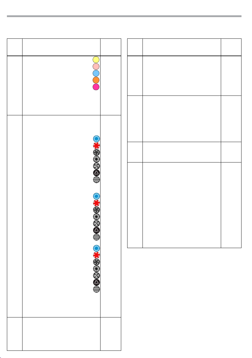
6
COLOR
Indexed
Position 1 (open)
Position 2 (red)
Position 3 (blue)
Position 4 (green)
Position 5 (yellow)
Position 6 (pink)
Position 7 (sky blue)
Position 8 (orange)
Position 9 (magenta)
Indexed with Backout
Position 1 (open)
Position 2 (red)
Position 3 (blue)
Position 4 (green)
Position 5 (yellow)
Position 6 (pink)
Position 7 (sky blue)
Position 8 (orange)
Position 9 (magenta)
Indexed with Bounce
Position 1 (open)
Position 2 (red)
Position 3 (blue)
Position 4 (green)
Position 5 (yellow)
Position 6 (pink)
Position 7 (sky blue)
Position 8 (orange)
Position 9 (magenta)
000 - 005
006 - 011
012 - 017
018 - 023
024 - 029
030 - 035
036 - 041
042 - 047
048 - 053
054 - 059
060 - 065
066 - 071
072 - 077
078 - 083
084 - 089
090 - 095
096 - 101
102 - 106
107 - 119
120 - 132
133 - 145
146 - 158
159 - 171
172 - 184
185 - 197
198 - 210
211 - 223
MODE FUNCTION DMX
Value
11 Ch
6
Forward Wheel Spin
Stop to fast
Reverse Wheel Spin
Stop to fast
224 - 239
240 - 255
7
ROT GOBO
Indexed
Position 1 (open)
Position 2
Position 3
Position 4
Position 5
Position 6
Position 7
Position 8
Indexed with Backout
Position 1 (open)
Position 2
Position 3
Position 4
Position 5
Position 6
Position 7
Position 8
Indexed with Shake
Position 2
Position 3
Position 4
Position 5
Position 6
Position 7
Position 8
Forward Wheel Spin
Stop to fast
Reverse Wheel Spin
Stop to fast
000 - 005
006 - 011
012 - 017
018 - 023
024 - 029
030 - 035
036 - 041
042 - 047
048 - 053
054 - 059
060 - 065
066 - 071
072 - 077
078 - 083
084 - 089
090 - 097
098 - 111
112 - 132
133 - 153
154 - 174
175 - 195
196 - 216
217 - 223
224 - 239
240 - 255
8
GOBO ROT
Continuous
Positioning from 0-360°
Forward Animate Rotate
Stop to fastest
Reverse Animate Rotate
Stop to fastest
Forward Spin
Stop to fastest
000 - 191
192 - 207
208 - 223
224 - 239

17
CRYSTAL
MODE FUNCTION DMX
Value
11 Ch
8Reverse Spin
Stop to fastest 240 - 255
9
PRISM & PRISM ROT
Prism
3 facets prism (open)
Prism Rot Spin
Forward Slow to fastest
Stop
Reverse Slow to fastest
000 - 003
004 - 127
128 - 131
132 - 255
10
FOCUS
Continuous
Focus In to Focus Out 000 - 255
11
CONTROL
Normal
Reset All
Pan & Tilt Reset
Color Reset
Gobo Reset
TBD
Other Reset
Display Off
Dispaly On
TBD
Hibernation
TBD
000 - 007
008 - 015
016 - 023
024 - 031
032 - 039
040 - 047
048 - 055
056 - 063
064 - 071
072 - 087
088 - 095
096 - 255
13 CHANNELS - BASIC 16 BIT
MODE FUNCTION DMX
Value
13 Ch
1PAN
0~100% 000 - 255
2PAN FINE
0~100% 000 - 255
3TILT
0~100% 000 - 255
4TILT FINE
0~100% 000 - 255
5MOVEMENT SPEED
Fast to slow 000 - 255
6
SHUTTER
Shutter closed
Strobe effect slow to fast
No function (shutter open)
000 - 031
032 - 223
224 - 255
7DIMMER
0~100% 000 - 255
8
COLOR
Indexed
Position 1 (open)
Position 2 (red)
Position 3 (blue)
Position 4 (green)
Position 5 (yellow)
Position 6 (pink)
Position 7 (sky blue)
Position 8 (orange)
Position 9 (magenta)
Indexed with Backout
Position 1 (open)
Position 2 (red)
Position 3 (blue)
Position 4 (green)
Position 5 (yellow)
Position 6 (pink)
Position 7 (sky blue)
Position 8 (orange)
Position 9 (magenta)
Indexed with Bounce
Position 1 (open)
Position 2 (red)
Position 3 (blue)
Position 4 (green)
000 - 005
006 - 011
012 - 017
018 - 023
024 - 029
030 - 035
036 - 041
042 - 047
048 - 053
054 - 059
060 - 065
066 - 071
072 - 077
078 - 083
084 - 089
090 - 095
096 - 101
102 - 106
107 - 119
120 - 132
133 - 145
146 - 158
CRYSTAL
18
MODE FUNCTION DMX
Value
13 Ch
10
Reverse Animate Rotate
Stop to fastest
Forward Spin
Stop to fastest
Reverse Spin
Stop to fastest
208 - 223
224 - 239
240 - 255
11
PRISM & PRISM ROT
Prism
3 facets prism (open)
Prism Rot Spin
Forward Slow to fastest
Stop
Reverse Slow to fastest
000 - 003
004 - 127
128 - 131
132 - 255
12
FOCUS
Continuous
Focus In to Focus Out 000 - 255
13
CONTROL
Normal
Reset All
Pan & Tilt Reset
Color Reset
Gobo Reset
TBD
Other Reset
Display Off
Dispaly On
TBD
Hibernation
TBD
000 - 007
008 - 015
016 - 023
024 - 031
032 - 039
040 - 047
048 - 055
056 - 063
064 - 071
072 - 087
088 - 095
096 - 255
MODE FUNCTION DMX
Value
13 Ch
8
Position 5 (yellow)
Position 6 (pink)
Position 7 (sky blue)
Position 8 (orange)
Position 9 (magenta)
Forward Wheel Spin
Stop to fast
Reverse Wheel Spin
Stop to fast
159 - 171
172 - 184
185 - 197
198 - 210
211 - 223
224 - 239
240 - 255
9
ROT GOBO
Indexed
Position 1 (open)
Position 2
Position 3
Position 4
Position 5
Position 6
Position 7
Position 8
Indexed with Backout
Position 1 (open)
Position 2
Position 3
Position 4
Position 5
Position 6
Position 7
Position 8
Indexed with Shake
Position 2
Position 3
Position 4
Position 5
Position 6
Position 7
Position 8
Forward Wheel Spin
Stop to fast
Reverse Wheel Spin
Stop to fast
000 - 005
006 - 011
012 - 017
018 - 023
024 - 029
030 - 035
036 - 041
042 - 047
048 - 053
054 - 059
060 - 065
066 - 071
072 - 077
078 - 083
084 - 089
090 - 097
098 - 111
112 - 132
133 - 153
154 - 174
175 - 195
196 - 216
217 - 223
224 - 239
240 - 255
10
GOBO ROT
Continuous
Positioning from 0-360°
Forward Animate Rotate
Stop to fastest
000 - 191
192 - 207
Table of contents
Languages:
Other Tribe Dj Equipment manuals

Tribe
Tribe LUMIPAR12UH3P User manual

Tribe
Tribe FLATPAR3H User manual

Tribe
Tribe JETSPOT4Z User manual

Tribe
Tribe LUMIPAR12UAW User manual

Tribe
Tribe LUMIPIX9UHE User manual

Tribe
Tribe PIXROLL10UTRI User manual

Tribe
Tribe BATGOBOIR User manual

Tribe
Tribe JETBEAM1 User manual

Tribe
Tribe FLATPAR3Q User manual

Tribe
Tribe SUNRISE2 User manual


