Tribe PIXROLL10UTRI User manual
Manuale Utente
User Manual
EN IT
PIXROLL10UTRI
LINEAR MOTORIZED PROJECTOR

PIXROLL10UTRI
2
All rights reserved by Music & Lights S.r.l. No part of this instruction manual may be
reproduced in any form or by any means for any commercial use.
In order to improve the quality of products, Music&Lights S.r.l. reserves the right to modify the
characteristics stated in this instruction manual at any time and without prior notice.
All revisions and updates are available in the ‘manuals’ section on site www.musiclights.it
REV.002-12/18

1
PIXROLL10UTRI
Packing content • PIXROLL10UTRI
• Mount bracket (OS10UTRI, optional)
• Power cable
• User manual
TABLE OF CONTENTS Safety
General instructions
Warnings and installation precautions
1 Introduction
1. 1 Description
1. 2 Technical specications
1. 3 Operating elements and connections
2 Installation
2. 1 Mounting
3 Functions and settings
3. 1 Operation
3. 2 Basic
3. 3 Menu structure
3. 8 DMX conguration
3. 9 DMX addressing
3. 6 Preset color
3. 11 Connection of the DMX line
3. 12 Construction of the DMX termination
3. 13 DMX control
3. 4 Automatic
3. 5 Music mode
3. 7 Custom static color
3. 10 Other functions
4 Maintenance
4. 1 Maintenance and cleaning the unit
4. 2 Fuse replacement
4. 3 Troubleshooting
2
2
3
3
5
6
7
7
8
9
9
9
10
10
11
16
16
16
16
17
17
18
PIXROLL10UTRI
2
WARNING! Before carrying out any operations with the unit, carefully read this instruction
manual and keep it with cure for future reference. It contains important information about
the installation, usage and maintenance of the unit.
SAFETY
General instruction
• The products referred to in this manual conform to the European Community Directives and are there-
fore marked with .
• The unit is supplied with hazardous network voltage (230V~). Leave servicing to skilled personnel only.
Never make any modications on the unit not described in this instruction manual, otherwise you will
risk an electric shock.
• Connection must be made to a power supply system tted with ecient earthing (Class I appliance ac-
cording to standard EN 60598-1). It is, moreover, recommended to protect the supply lines of the units
from indirect contact and/or shorting to earth by using appropriately sized residual current devices.
• The connection to the main network of electric distribution must be carried out by a qualied electrical
installer. Check that the main frequency and voltage correspond to those for which the unit is designed
as given on the electrical data label.
• This unit is not for home use, only professional applications.
• Never use the xture under the following conditions:
- in places subject to vibrations or bumps;
- in places with a temperature of over 45°C.
• Make certain that no inammable liquids, water or metal objects enter the xture.
• Do not dismantle or modify the xture.
• All work must always be carried out by qualied technical personnel. Contact the nearest sales point for
an inspection or contact the manufacturer directly.
• If the unit is to be put out of operation denitively, take it to a local recycling
plant for a disposal which is not harmful to the environment.
Warnings and installation precautions
• The unit for indoor use only. To prevent or reduce the risk of electrical shock or re, do not expose the
unit to rain or moisture.
• If this device will be operated in any way dierent to the one described in this manual, it may suer
damage and the guarantee becomes void. Furthermore, any other operation may lead to dangers like
short circuit, burns, electric shock, etc.
• Before starting any maintenance work or cleaning the projector, cut o power from the main supply.
• Always additionally secure the projector with the safety rope.When carrying out any work, always com-
ply scrupulously with all the regulations (particularly regarding safety) currently in force in the country
in which the xture’s being used.
• Install the xture in a well ventilated place.
• The minimum distance between the xture and surrounding walls must be more than 50 cm and the
air vents at the housing must not be covered in any case.
• Do not touch the product’s housing when operating because it may be very hot.
• Keep any inammable material at a safe distance from the xture.
• Shields, lenses or ultraviolet screens shall be changed if they have become damaged to such an extent
that their eectiveness is impaired.
• The lamp (LED) shall be changed if it has become damaged or thermally deformed.
• Never look directly at the light beam. Please note that fast changes in lighting, e. g. ashing light, may
trigger epileptic seizures in photosensitive persons or persons with epilepsy.

3
PIXROLL10UTRI
- 1 - INTRODUCTION
1.1 DESCRIPTION
PIXROLL10UTRI is a motorised linear LED luminaire designed to be bright and add movements on the
stage.The light source is composed of 10x7.2W RGB/FC LED that can be controlled in the pixel2pixel mode
with 250° motorised tilt inclination through DMX. The motorisation of the tilt axis allows the addition of
numerous options to this light, such as the creation of partitions, barriers or mobile virtual doors.
FEATURES:
• 10x7.2W RGB/FC high-eciency LED
• Pixel control of every individual LED
• Motorised tilt axis with rotation to 250°
• Flicker-free operations
1.2 TECHNICAL SPECIFICATIONS
LIGHT SOURCE
• Source:10x7.2W RGB LEDs
• Luminous Flux: 2150lm
• Lux: 2541lux @3m
• Source Life Expectancy: >50.000 h
OPTICS
• Beam Angle: 15°
• Field Angle: 25°
COLOR SYSTEM
• Color Mixing: RGB/FC
• CTC: CTC control through independent DMX channel
• Color Wheel: Virtual color wheel with presets
DYNAMIC EFFECTS
• Pixel Patterns: Preprogrammed dynamic and static patterns
• Special Features: Motorized Tilt 0-250°
BODY
• Tilt Angle: 0-250°
• Body: Aluminium structure with hi-resistance polycarbonate cover
• Body Color: Black
CONTROL
• Protocols: DMX512
• DMX channels:5,6,8,10,17,32,36 channel
• Pixel control: pixel2pixel control
• W-DMX: optional, proprietary protocol compatible with WIFIBOX, WDBOX
• Display: LED display user interface
• IR: infrared sensor controlled by remote
• Master/Slave: for synchronized operation of more units linked in a chain
PIXROLL10UTRI
4
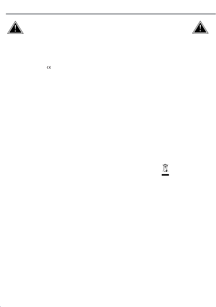
785
123
67
Fig.1
ELECTRONICS
• Dimmer: linear 0~100% electronic dimmer
• Dimmer curves:4 dierent dimming curves available
• Strobe / shutter:1-30 Hz, electronic
• Operating temperature: -10° ~ +40°
• Flicker: icker free operation
ELECTRICAL
• Power Supply: 100-240V – 50/60Hz
• Power Consumption (at 230V): 82.8W
• Power Consumption (at 120V): 85W
• Output (at 230V): 6 units on a single power line
PHYSICAL
• Cooling: forced air with low noise fan
• Sospension and xing: hanging bracket suitable for safe hanging and positioning
• Data: USB port for USB WIFI transmitter (optional)
• Signal connection: XLR 3p IN/OUT connectors
• Power connection: IEC IN/OUT connectors
• IP rating:20
• Dimensions (WxHxD):785x123x67 mm
• Weight:4.3 kg
5
PIXROLL10UTRI
8
4
567
2
1
3
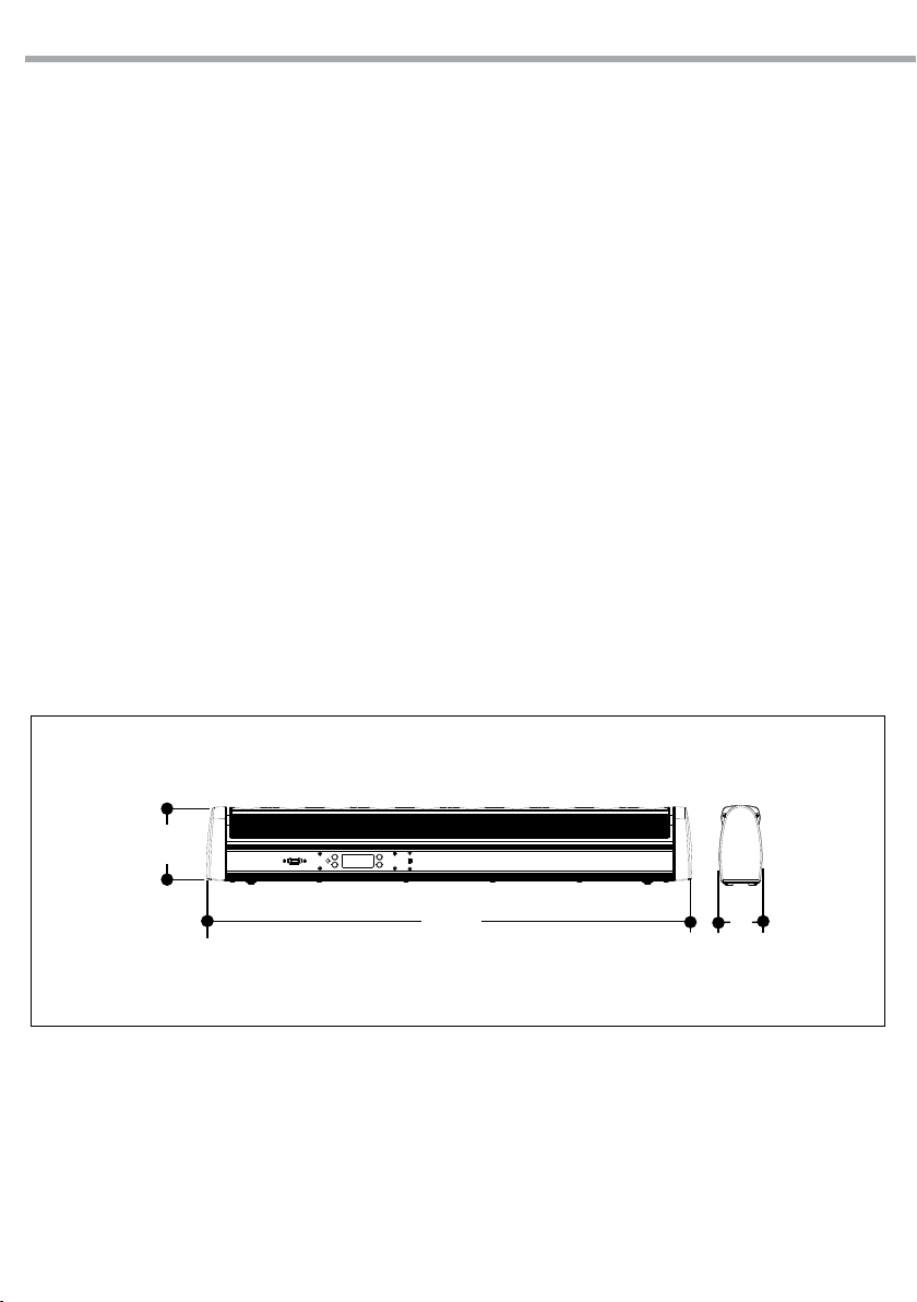
Fig.2
Rear panel
1.3 OPERATING ELEMENTS AND CONNECTIONS
1. LED BAR
2. CONTROL PANEL with display and 4 button
used to access the control panel functions and
manage them.
3. AUDIO SENSITIVITY REGULATOR in sound mode
4. POWER IN mains plug for connection to a socket
(100-240V 50/60Hz) via the supplied mains
cable. The support for the mains fuse is located
near the mains plug. Only replace a blown fuse
by one of the same type.
5. GND POINT Used to Ground the Devices
6. POWER OUT power output for connection of
multiple units in series.
7. DMX IN (3-pole XLR):
1 = ground, 2 = DMX -, 3 = DMX +
8. DMX OUT (3-pole XLR):
1= ground, 2 = DMX -, 3 = DMX +.

PIXROLL10UTRI
6
- 2 - INSTALLATION
CLAMP
SAFETY
CABLE
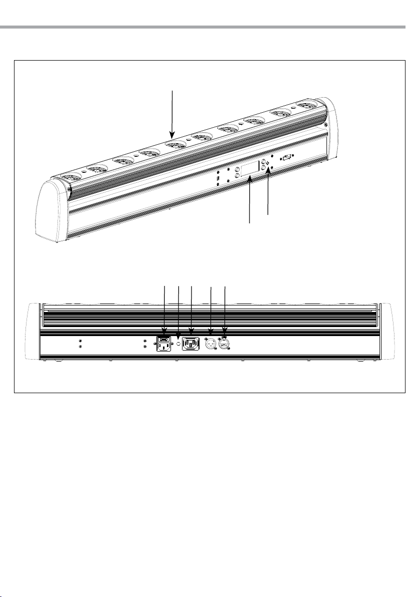
2.1 MOUNTING
PIXROLL10UTRI may be set up on a solid and even surface. The unit can also be mounted upside down, to
a cross arm. For xing, stable mounting clips are required. The mounting place must be of sucient stabil-
ity and be able to support a weight of 10 times of the unit’s weight.
When carrying out any installation, always comply scrupulously with all the regulations (particularly re-
garding safety) currently in force in the country in which the xture’s being used.
• Install the projector at a suitable location by means of the mounting bracket.
• Always additionally secure the projector with the safety rope from falling down. For this purpose, fas-
ten the safety rope at a suitable position so that the maximum fall of the projector will be 20 cm.
Fig.3
7
PIXROLL10UTRI
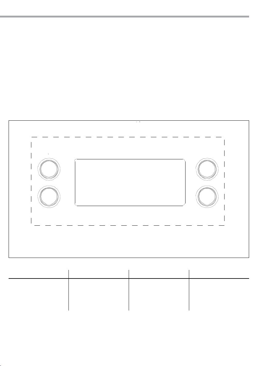
MENU UP DOWN ENTER
Used to scroll through the
current operating mode, as
well as back out of the current
menu option
Used to select an increasing
value
Used to select a decreasing
value
Used to activate a selection
and store it to memory
- 3 - FUNCTIONS AND SETTINGS
3.1 OPERATION
Connect the supplied main cable to a socket (100-240 VAC-50/60 Hz). Then the unit is ready for operation
and can be operated via a DMX controller or it independently performs its show program in succession.
To switch o, disconnect the mains plug from the socket. For a more convenient operation it is recom-
mended to connect the unit to a socket which can be switched on and o via a light switch.
3.2 BASIC
Access control panel functions using the four panel buttons located directly underneath the LED Display
(g.4).
Fig.4
MENU’
ENTER
UP
DOWN

PIXROLL10UTRI
8
3.3 MENU STRUCTURE
MAIN FUNCTION SUB-SELECTION DESCRIPTION
1 5 CH
<d001-d512> Choose DMX address
2 6 CH
3 8 CH
4 10 CH
5 17 CH
6 32 CH
7 36 CH
8 C-- <C1-C18> Preset color
9T-- <T0-T100> 000 - 050 Vertical position
051 - 100 Motor auto speed (Slow to Fast)
10 P-- <P1-P14> LED Auto program P14
Random auto program P1-P13
11 S-- <S1-S100> LED Auto program speed
12 Snd Sound control mode
13 Sens <u0-u100> Sound Sensitivity control
14 U--
<r0-r255>
Custom color setting and Vertical position<g0-g255>
<b0-b255>
15 Set <OFF-ON> Encoder switch
16 DIM
OFF Dimming curve o
DIM 1 Dimming curve: dim1
DIM 2 Dimming curve: dim2
DIM 3 Dimming curve: dim3
17 OFFS 000 - 255 Oset (calibration mode)

9
PIXROLL10UTRI
3.4 DMX CONFIGURATION
Il PIXROLL10UTRI is equipped with dierent DMX conguration.
• Press the button MENU to select the DMX conguration: [5 CH], [6-CH], [8-CH], [10-CH], [17-CH], [32-CH], [36 CH].
• Press the button ENTER to save the setting.
• Using UP/DOWN button, select the desired value [001 - 512].
• Press the button ENTER to conrm.
The tables on page 13 indicate the operating mode and DMX value. The PIXROLL10UTRI is equipped with
3-pole XLR connections.
3.5 DMX ADDRESSING
To able to operate the PIXROLL10UTRI with a light controller, adjust the DMX start address for the rst a
DMX channel. If e. g. address 33 on the controller is provided for controlling the function of the rst DMX
channel, adjust the start address 33 on the PIXROLL10UTRI. The other functions of the light eect panel
are then automatically assigned to the following addresses.
3.6 PRESET COLOR
This xture has preprogrammed, static looks that may be triggered without a controller.
• Press the button MENU so many times until shows [C--], and press the button ENTER to conrm.
• Select the desired preset color [C1 - C18] through the buttons UP/DOWN.
• Press ENTER button to conrm.

PIXROLL10UTRI
10
3.7 CONNECTION OF THE DMX LINE
DMX connection employs standard XLR connectors. Use shielded pair-twisted cables with 120Ω imped-
ance and low capacity.
The following diagram shows the connection mode:
ATTENTION
The screened parts of the cable (sleeve) must never be connected to the system’s earth, as this would
cause faulty xture and controller operation.
Over long runs can be necessary to insert a DMX level matching amplier.
For those connections the use of balanced microphone cable is not recommended because it cannot
transmit control DMX data reliably.
• Connect the controller DMX input to the DMX output of the rst unit.
• Connect the DMX output to the DMX input of the following unit. Connect again the output to the input
of the following unit until all the units are connected in chain.
• When the signal cable has to run longer distance is recommended to insert a DMX termination on the
last unit.
3.8 CONSTRUCTION OF THE DMX TERMINATION
The termination avoids the risk of DMX 512 signals being reected back along the cable when they reach-
es the end of the line: under certain conditions and with certain cable lengths, this could cause them to
cancel the original signals.
The termination is prepared by soldering a 120Ω 1/4 W resistor with pins 2 and 3 pin male XLR connector,
as shown in gure.
DMX - OUTPUT
XLR socket
DMX - INPUT
XLR plug
Pin1 : GND - Shield
Pin2 : - Negative
Pin3 : + Positive
Pin4 : N/C
Pin5 : N/C
Fig.6
Example:
3 pin XLR connector
Fig.7

11
PIXROLL10UTRI
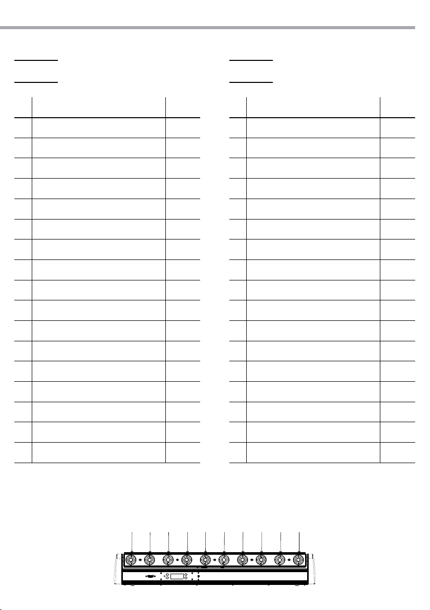
3.9 DMX CONTROL
CH5
CH Function in Ch 5 mode Value
1RED 0 - 100% 000 - 255
2GREEN 0 - 100% 000 - 255
3BLUE 0 - 100% 000 - 255
4TILT 0 - 250° 000 - 255
5TILT SPEED Fast - Slow 000 - 255
CH6
CH Function in Ch 6 mode Value
1RED 0 - 100% 000 - 255
2GREEN 0 - 100% 000 - 255
3BLUE 0 - 100% 000 - 255
4DIMMER 0 - 100% 000 - 255
5TILT 0 - 250° 000 - 255
6TILT SPEED Fast - Slow 000 - 255
CH8
6
7
8
9
10 54321
CH8
CH Function in Ch 8 mode Value
1RED (1-5) 0 - 100% 000 - 255
2GREEN (1-5) 0 - 100% 000 - 255
3BLUE (1-5) 0 - 100% 000 - 255
4RED (6-10) 0 - 100% 000 - 255
5GREEN (6-10) 0 - 100% 000 - 255
6BLUE (6-10) 0 - 100% 000 - 255
7TILT 0 - 250° 000 - 255
8TILT SPEED Fast - Slow 000 - 255

PIXROLL10UTRI
12
CH10
CH Function in Ch 10 mode Value
1RED 0 - 100% 000 - 255
2GREEN 0 - 100% 000 - 255
3BLUE 0 - 100% 000 - 255
4
COLOR MACROS
No function
Color Macros
000 - 015
016 - 255
5
STROBE
No function
Strobe (slow to fast)
000 - 015
016 - 255
SPEED
When CH6 is 32 - 223
Chase speed (slow to fast)
000 - 255
SOUND SENSITIVITY
Sound sensitivity OFF
Control the sound sensitivity
000 - 010
011 - 255
6
AUTO CHASE
No function
Chase 1
Chase 2
Chase 3
Chase 4
Chase 5
Chase 6
Chase 7
Chase 8
Chase 9
Chase 10
Chase 11
Chase 12
Chase 13
Chase 14 (Random Chase 1-13)
Sound Active
000 - 031
032 - 045
046 - 059
060 - 072
073 - 086
087 - 100
101 - 113
114 - 127
128 - 141
142 - 154
155 - 168
169 - 182
183 - 195
196 - 209
210 - 223
224 - 255
6
7
8
9
10 54321
CH Function in Ch 10 mode Value
7DIMMER 0 - 100% 000 - 255
8TILT 0 - 250° 000 - 255
9TILT SPEED Fast - Slow 000 - 255
10
DIMMER MODE
Menu setting Dimmer mode
Dimmer mode O
Dimmer mode 1
Dimmer mode 2
Dimmer mode 3
000 - 051
052 - 101
102 - 152
153 - 203
204 - 255
13
PIXROLL10UTRI
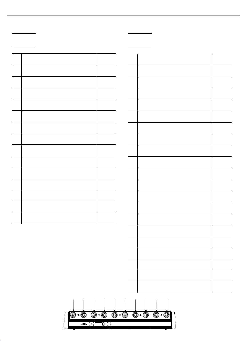
CH17 CH32
CH Function in Ch 17 mode Value
1RED 1 0 - 100% 000 - 255
2GREEN 1 0 - 100% 000 - 255
3BLUE 1 0 - 100% 000 - 255
4RED 2 0 - 100% 000 - 255
5GREEN 2 0 - 100% 000 - 255
6BLUE 2 0 - 100% 000 - 255
7RED 3 0 - 100% 000 - 255
8GREEN 3 0 - 100% 000 - 255
9BLUE 3 0 - 100% 000 - 255
10 RED 4 0 - 100% 000 - 255
11 GREEN 4 0 - 100% 000 - 255
12 BLUE 4 0 - 100 000 - 255
13 RED 5 0 - 100% 000 - 255
14 GREEN 5 0 - 100% 000 - 255
15 BLUE 5 0 - 100 000 - 255
16 TILT 0 - 250° 000 - 255
17 TILT SPEED Fast - Slow 000 - 255
CH Function in Ch 32 mode Value
1RED 1 0 - 100% 000 - 255
2GREEN 1 0 - 100% 000 - 255
3BLUE 1 0 - 100% 000 - 255
4RED 2 0 - 100% 000 - 255
5GREEN 2 0 - 100% 000 - 255
6BLUE 2 0 - 100% 000 - 255
7RED 3 0 - 100% 000 - 255
8GREEN 3 0 - 100% 000 - 255
9BLUE 3 0 - 100% 000 - 255
10 RED 4 0 - 100% 000 - 255
11 GREEN 4 0 - 100% 000 - 255
12 BLUE 4 0 - 100% 000 - 255
13 RED 5 0 - 100% 000 - 255
14 GREEN 5 0 - 100% 000 - 255
15 BLUE 5 0 - 100% 000 - 255
16 RED 6 0 - 100% 000 - 255
17 GREEN 6 0 - 100% 000 - 255
6
7
8
9
10 54321
PIXROLL10UTRI
14
6
7
8
9
10 54321
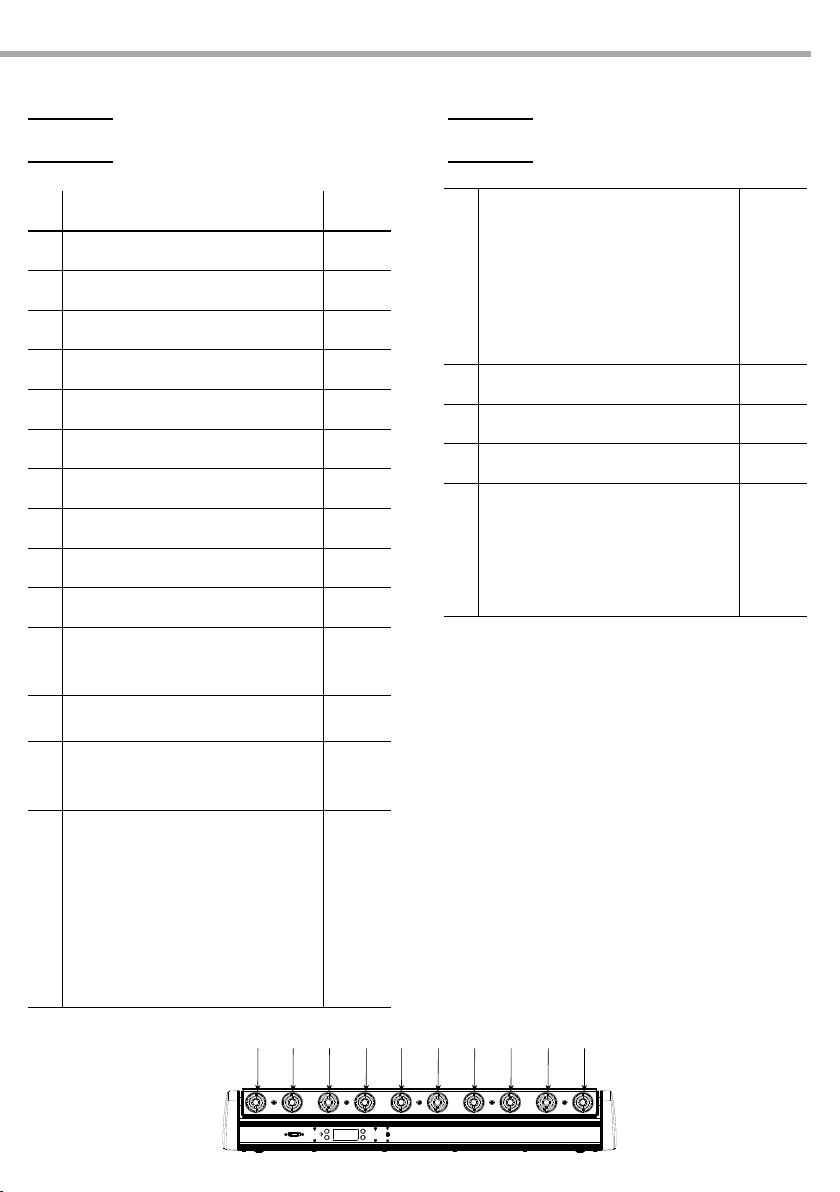
CH36
CH Function in Ch 36 mode Value
1RED 1 0 - 100% 000 - 255
2GREEN 1 0 - 100% 000 - 255
3BLUE 1 0 - 100% 000 - 255
4RED 2 0 - 100% 000 - 255
5GREEN 2 0 - 100% 000 - 255
6BLUE 2 0 - 100% 000 - 255
7RED 3 0 - 100% 000 - 255
8GREEN 3 0 - 100% 000 - 255
9BLUE 3 0 - 100% 000 - 255
10 RED 4 0 - 100% 000 - 255
11 GREEN 4 0 - 100% 000 - 255
12 BLUE 4 0 - 100% 000 - 255
13 RED 5 0 - 100% 000 - 255
14 GREEN 5 0 - 100% 000 - 255
15 BLUE 5 0 - 100% 000 - 255
16 RED 6 0 - 100% 000 - 255
17 GREEN 6 0 - 100% 000 - 255
18 BLUE 6 0 - 100% 000 - 255
19 RED 7 0 - 100% 000 - 255
20 GREEN 7 0 - 100% 000 - 255
18 BLUE 6 0 - 100% 000 - 255
19 RED 7 0 - 100% 000 - 255
20 GREEN 7 0 - 100% 000 - 255
21 BLUE 7 0 - 100% 000 - 255
22 RED 8 0 - 100% 000 - 255
23 GREEN 8 0 - 100% 000 - 255
24 BLUE 8 0 - 100% 000 - 255
25 RED 9 0 - 100% 000 - 255
26 GREEN 9 0 - 100% 000 - 255
27 BLUE 9 0 - 100% 000 - 255
28 RED 10 0 - 100% 000 - 255
39 GREEN 10 0 - 100% 000 - 255
30 BLUE 10 0 - 100% 000 - 255
31 TILT 0 - 250° 000 - 255
32 TILT SPEED Fast - Slow 000 - 255
CH32
15
PIXROLL10UTRI
CH36
CH Function in Ch 38 mode Value
21 BLUE 7 0 - 100% 000 - 255
22 RED 8 0 - 100% 000 - 255
23 GREEN 8 0 - 100% 000 - 255
24 BLUE 8 0 - 100% 000 - 255
25 RED 9 0 - 100% 000 - 255
26 GREEN 9 0 - 100% 000 - 255
27 BLUE 9 0 - 100% 000 - 255
28 RED 10 0 - 100% 000 - 255
29 GREEN 10 0 - 100% 000 - 255
30 BLUE 10 0 - 100% 000 - 255
31
STROBE
No function
Strobe (slow to fast)
000 - 015
016 - 255
SPEED
Chase speed (slow to fast) 000 - 255
SOUND SENSITIVITY
Sound sensitivity OFF
Control the sound sensitivity
000 - 010
011 - 255
32
AUTO CHASE
No function
Chase 1
Chase 2
Chase 3
Chase 4
Chase 5
Chase 6
Chase 7
000 - 031
032 - 045
046 - 059
060 - 072
073 - 086
087 -100
101 - 113
114 - 127
6
7
8
9
10 54321
CH36
Chase 8
Chase 9
Chase 10
Chase 11
Chase 12
Chase 13
Chase 14 (Random Chase 1-13)
Sound Active
128 - 141
142 - 154
155 - 168
169 - 182
183 - 195
196 - 209
210 - 223
224 - 255
33 DIMMER 0 - 100% 000 - 255
34 TILT 0 - 250° 000 - 255
35 TILT SPEED Fast - Slow 000 - 255
36
DIMMER MODE
Menu setting Dimmer mode
Dimmer mode O
Dimmer mode 1
Dimmer mode 2
Dimmer mode 3
000 - 051
052 - 101
102 - 152
153 - 203
204 - 255

PIXROLL10UTRI
16
3.10 AUTOMATIC
This xture has preprogrammed chases that may be triggered without a controller. Access these chases
via the control panel on the back of the xture.
• Press the button MENU so many times until shows [P--], and press the button ENTER.
• Select the program [P1 - P14] through the buttons UP/DOWN. Press the button ENTER to conrm. The
unit will operate in auto mode
• For the auto programs speed, press the button MENU until [S--] appears on the display. Use the button
UP/DOWN to select the desired value [S1-S100] (slow-fast).
• For the tilt adjustments, press the button MENU until [t--] appears on the display. Use the button UP/
DOWN to select the desired value [t1- t100].
NOTE - You can set the value for the Vertical position (000 - 050) or for Motor auto speed (051 - 100).
3.11 MUSIC MODE
In music mode, via its integrated microphone, the unit can be controlled by music with a clear rhythm in
the bass range. If the music control should not work optimally, increase the volume or reduce the distance
between the sound source and the light eect unit.
• Press the button MENU so many times until the display shows [SNd], then press the button ENTER.
• Use the microphone sensitivity adjustment knob to adjust the xture to react to the beat of the music.
3.12 CUSTOM STATIC COLOR
This xture has the ability to accept custom static color settings. Access this via the control panel.
• Press the button MENU so many times until shows [U--], and press the button ENTER to conrm.
• Select with the button ENTER the desired color [r - g - b].
• Using UP/DOWN button, select the desired color value [000 - 255]. By selecting 000, the color will remain o.
• Continue until the desired mix is obtained.
• Press ENTER button to continue to the tilt setting [t] .
• Using UP/DOWN button, select the desired value [000 - 255].
• Press ENTER button to conrm.
3.13 OTHERS FUNCTIONS
It is possible to change the parameter value in the following way:
Dimmer
Enter [DIM] to select dimmer mode and dimmer speed. When dimmer is set to [OFF], the dimmer is linear.
DIM1/2/3 are speed modes of the linear dimmer; [DIM1] is the faster, while [DIM3] is the slowest.
Offset
To set the corrective values (oset mode) for the tilt:
• Press the button MENU so many times until shows [OFFS], and press the button ENTER to conrm.
• Using UP/DOWN button, select the desired value [001 -255].
• Press the button ENTER to save the setting.

17
PIXROLL10UTRI
Fuse
Fig.8
- 4 - MAINTENANCE
4.1 MAINTENANCE AND CLEANING THE UNIT
• Make sure the area below the installation place is free from unwanted persons during setup.
• Switch o the unit, unplug the main cable and wait until the unit has cooled down.
• All screws used for installing the device and any of its parts should be tightly fastened and should not
be corroded.
• Housings, xations and installation spots (ceiling, trusses, suspensions) should be totally free from any
deformation.
• The main cables must be in impeccable condition and should be replaced immediately even when a
small problem is detected.
• It is recommended to clean the front at regular intervals, from impurities caused by dust, smoke, or
other particles to ensure that the light is radiated at maximum brightness. For cleaning, disconnect the
main plug from the socket. Use a soft, clean cloth moistened with a mild detergent. Then carefully wipe
the part dry. For cleaning other housing parts use only a soft, clean cloth. Never use a liquid, it might
penetrate the unit and cause damage to it.
Warning: we strongly recommend internal cleaning to be carried out by qualied personnel!
4.2 FUSE REPLACEMENT
1. Remove the safety cap by a screwdriver.
2. Replace the blown fuse with a fuse of the exact same type and rating (T2A).
3. Install the safety cap, and reconnect power.

PIXROLL10UTRI
18
Problems Possible causes Checks and remedies
Fixture does not light up
• No mains supply
• Dimmer fader set to 0
• All color faders set to 0
• Faulty LED
• Faulty LED board
• Check the power supply voltage
• Increase the value of the dimmer channels
• Increase the value of the color channels
• Replace the LED board
• Replace the LED board
General low light intensity • Dirty lens assembly
• Misaligned lens assembly
• Clean the xture regularly
• Install lens assembly properly
Fixture does not power up
• No power
• Loose or damaged power cord
• Faulty internal power supply
• Check for power on power outlet
• Check power cord
• Replace internal power supply
Fixture does not respond to DMX
• Wrong DMX addressing
• Damaged DMX cables
• Bouncing signals
• Check control panel and unit addressing
• Check DMX cables
• Install terminator as suggested
Contact an authorized service center in case of technical problems or not reported in the table can not be
resolved by the procedure given in the table.
4.3 TROUBLESHOOTING
Table of contents
Languages:
Other Tribe Dj Equipment manuals

Tribe
Tribe PROLIGHTS SMARTBATTENQ User manual

Tribe
Tribe Crystal User manual

Tribe
Tribe JETSPOT4Z User manual

Tribe
Tribe SUNRISE2 User manual

Tribe
Tribe FLATPAR3H User manual

Tribe
Tribe JETSPOT1 User manual

Tribe
Tribe FLATPAR3Q User manual

Tribe
Tribe LUMIPAR 12UQ PRO User manual

Tribe
Tribe MINIVERSAPAR User manual

Tribe
Tribe LUMIPAR12UAW User manual


Popular Dj Equipment manuals by other brands


Magicfx
Magicfx MFX1201 user manual

IMG STAGE LINE
IMG STAGE LINE PAR-16M/CR instruction manual

Rocket Fish
Rocket Fish RF-GSL010A Guía De Instalación Rápida

WalimeXPro
WalimeXPro LED Niova 150-F Pro 150W Bi Color manual

SilverStar
SilverStar SHOWPRO LEDFRE102 user manual

SilverStar
SilverStar YG-LED833 user manual