Tribe LUMIPIX9UHE User manual
USER MANUAL
MANUALE UTENTE
LUMIPIX9UHE
EN - IT
LINEAR LED BATTEN

All rights reserved by Music & Lights S.r.l. No part of this instruction manual may be
reproduced in any form or by any means for any commercial use.
In order to improve the quality of products, Music&Lights S.r.l. reserves the right to modify the
characteristics stated in this instruction manual at any time and without prior notice.
All revisions and updates are available in the ‘manuals’ section on site www.musiclights.it
REV.003-05/17

1
LUMIPIX9UHE
Packing content • LUMIPIX9UHE
• Mount bracket (2pc.)
• Power cable
• User manual
TABLE OF CONTENTS Safety
General instructions
Warnings and installation precautions
General information
1 Introduction
1. 1 Description
1. 2 Technical specications
1. 3 Operating elements and connections
2 Installation
2. 1 Mounting
3 Functions and settings
3. 1 Operation
3. 2 Basic
3. 3 Menu structure
3. 4 Auto Show
3. 5 Static color
3. 6 Sound mode
3. 7 Manual color
3. 8 Master/Slave mode
3. 9 Linking
3. 10 DMX mode
3. 11 DMX addressing
3. 12 Connection of the DMX line
3. 13 Construction of the DMX termination
3. 14 DMX control
3. 15 Dimmer
3. 16 Operation through the IRC Controller
4 Maintenance
4. 1 Maintenance and cleaning the unit
4. 2 Fuse replacement
4. 3 Trouble shooting
Warranty
2
2
3
4
4
6
7
8
8
9
10
10
10
11
11
11
11
11
13
13
14
17
17
19
19
19
LUMIPIX9UHE
2
SAFETY
General instruction
• The products referred to in this manual conform to the European Community Directives and are there-
fore marked with .
• The unit is supplied with hazardous network voltage (230V~). Leave servicing to skilled personnel only.
Never make any modications on the unit not described in this instruction manual, otherwise you will
risk an electric shock.
• Connection must be made to a power supply system tted with ecient earthing (Class I appliance ac-
cording to standard EN 60598-1). It is, moreover, recommended to protect the supply lines of the units
from indirect contact and/or shorting to earth by using appropriately sized residual current devices.
• The connection to the main network of electric distribution must be carried out by a qualied electrical
installer. Check that the main frequency and voltage correspond to those for which the unit is designed
as given on the electrical data label.
• This unit is not for home use, only professional applications.
• Never use the xture under the following conditions:
- in places subject to vibrations or bumps;
- in places with a temperature of over 45 °C.
• Make certain that no inammable liquids, water or metal objects enter the xture.
• Do not dismantle or modify the xture.
• All work must always be carried out by qualied technical personnel. Contact the nearest sales point for
an inspection or contact the manufacturer directly.
• If the unit is to be put out of operation denitively, take it to a local recycling
plant for a disposal which is not harmful to the environment.
Warnings and installation precautions
• If this device will be operated in any way dierent to the one described in this manual, it may suer
damage and the guarantee becomes void. Furthermore, any other operation may lead to dangers like
short circuit, burns, electric shock, etc.
• Before starting any maintenance work or cleaning the projector, cut o power from the main supply.
• Always additionally secure the projector with the safety rope.When carrying out any work, always com-
ply scrupulously with all the regulations (particularly regarding safety) currently in force in the country
in which the xture’s being used.
• Install the xture in a well ventilated place.
• Keep any inammable material at a safe distance from the xture.
• Shields, lenses or ultraviolet screens shall be changed if they have become damaged to such an extent
that their eectiveness is impaired.
• The lamp (LED) shall be changed if it has become damaged or thermally deformed.
• Never look directly at the light beam. Please note that fast changes in lighting, e. g. ashing light, may
trigger epileptic seizures in photosensitive persons or persons with epilepsy.
• Do not touch the product’s housing when operating because it may be very hot.
WARNING! Before carrying out any operations with the unit, carefully read this instruction
manual and keep it with cure for future reference. It contains important information about
the installation, usage and maintenance of the unit.

3
LUMIPIX9UHE
- 1 - INTRODUCTION
1.1 DESCRIPTION
LUMIPIX9UHE is a 1m linear LED batten using an innovative optic system combined with a new light
source which performs a colour mixing of 6 primary colours - RGBWA. The light source is composed of
9x8W high-eciency RGBWAP full colour LED oering a more advanced chromatic synthesis than pro-
jectors of the previous generation, with full control of saturation and colour temperature on the whole
spectrum. LUMIPIX9UHE oers a 3 section control of the LED plate to generate a wide range of dynamic
eects and light-yokes.
1.2 TECHNICAL SPECIFICATIONS
LIGHT SOURCE
• Source: 9x8W RGBWAP LEDs
• Luminous ux: (15°) 2068lm
• Lux: 1080lux @3m
• Source life expectancy: >50.000 h
OPTICS
• Beam angle: 23°
• Field angle: 40°
• Lens diameter: 42mm
• Additional optics: 25° and 45° (optional)
COLOUR SYSTEM
• Colour mixing: RGBWAP/FC
• Colour wheel: virtual colour wheel with presets
• Macros: several pre-build pixel macros with adjustable speed
DYNAMIC EFFECTS
• Static colour mode: selection of static colour
• Manual colour mode: manual adjustment of colour
• Auto mode: built-in programs with execution speed adjustment
• Sound mode: music activation through internal microphone and sensitivity control
BODY
• Body: sturdy die-cast aluminium body conceived for long-time durability
• Body colour: black
CONTROL
• Protocols: DMX512
• DMX channels: 6/9/11/18/23channel
• Pixel control: 1/3 section control
• Display: LED display user interface
• Firmware upgrade: yes, via USB-DMX interface (UPBOX1) not included
• IR: infrared sensor controlled by remote
• Master/Slave: for synchronized operation of more units linked in a chain
ELECTRONICS
• Dimmer: linear 0~100% electronic dimmer
• Dimmer curves: 4 dierent dimming curves available
• Strobe / shutter: 1-25 Hz, electronic
• Operating temperature: -20° ~ +45°
• Flicker: icker free operation
ELECTRICAL
• Power supply: 100-240V – 50/60Hz
LUMIPIX9UHE
4
• Power consumption (at 230V): 78,5W
• Power consumption (at 120V): 79W
• Output (at 230V): 15 units on a single power line
• Output (at 120V): 9 units on a single power line
PHYSICAL
• Cooling: natural cooling of the peculiar chassis and to absence of fans
• Sospension and xing: double hanging bracket suitable for safe hanging and for oor positioning
• Data: USB port for USB WIFI transmitter (optional)
• Signal connection: XLR 3p IN/OUT connectors
• Power connection: IEC IN/OUT connectors
• IP rating: 30
• Dimensions (WxHxD): 1000x55x168mm
• Weight: 3.23kg
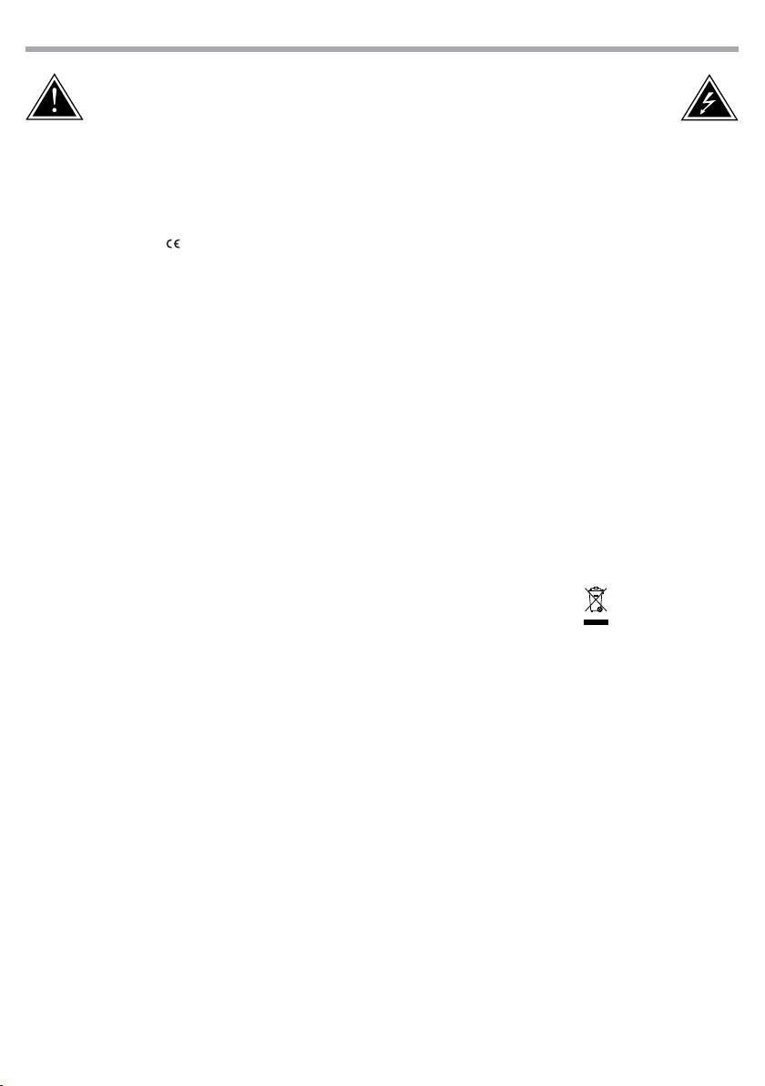
Fig.1Photometric data
Technical drawing
1000
56
168
I
lluminan
ce at a Distance
24°
1.0m
0m
3.0m
5.0m
7.0m
10.0m
0.37m
1.11m
1.85m
2.60m
Lux Center Beam Angle: 24° Beam Width
9719lx
1080lx
388,8lx
198,3lx
3.71m97,19lx
5
LUMIPIX9UHE
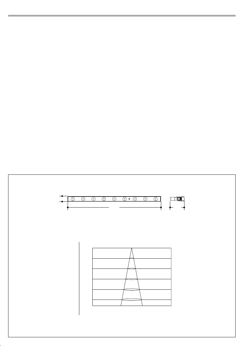
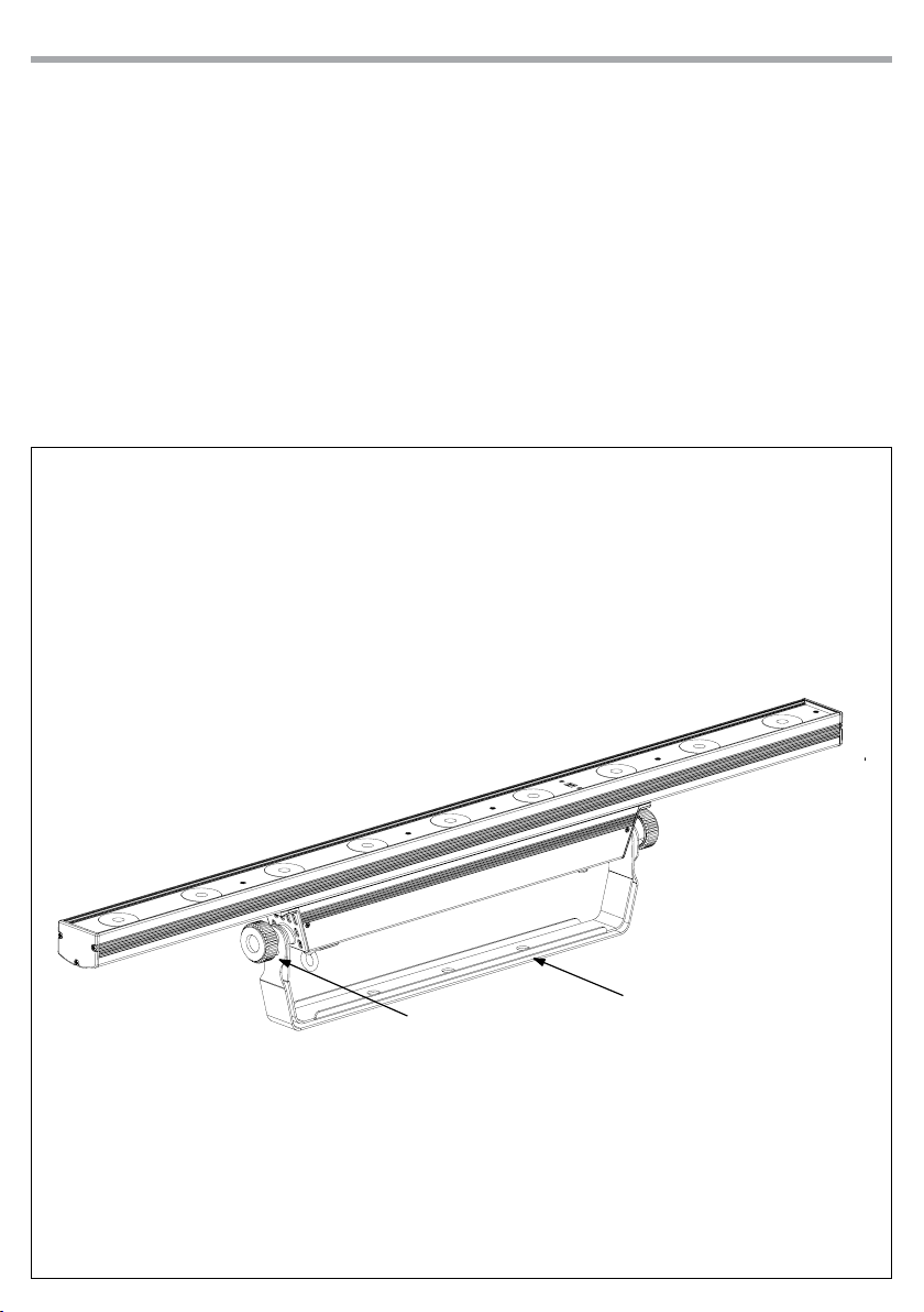
1.3 OPERATING ELEMENTS AND CONNECTIONS
Fig.2
1. MOUNTING BRACKET
2. LOCKING KNOB for the mounting bracket
3. SAFETY RING to attach safety cable
4. GND POINT grounding the xture to the earth
5. POWER IN mains plug for connection to a
socket (100-240V 50/60Hz) via the supplied
mains cable. The support for the mains fuse
is located near the mains plug. Only replace a
blown fuse by one of the same type (T2A/250V)
6. POWER OUT: connect to supply power to the
next unit.
Rear panel
7. MICROPHONE to control the show by the
external audio signal
8. CONTROL PANEL with display and 4 button
used to access the control panel functions
and manage them
9. DMX IN (3-pole XLR):
1 = ground, 2 = DMX -, 3 = DMX +
10. DMX OUT (3-pole XLR):
1= ground, 2 = DMX -, 3 = DMX +
11. Universal Serial Bus (USB)
358 10
9
47
611
1
2
LUMIPIX9UHE
6
- 2 - INSTALLATION
2.1 MOUNTING
LUMIPIX9UHE may be set up on a solid and even surface. The unit can also be mounted upside down to a
cross arm. For xing, stable mounting clips are required. The mounting place must be of sucient stability
and be able to support a weight of 10 times of the unit’s weight.
When carrying out any installation, always comply scrupulously with all the regulations (particularly re-
garding safety) currently in force in the country in which the xture’s being used.
• Install the projector at a suitable location by means of the mounting bracket (1).
• Always additionally secure the projector with the safety rope from falling down. For this purpose, fas-
ten the safety rope at a suitable position so that the maximum fall of the projector will be 20 cm.
• Adjust the projector and use the knob (2) to slightly release or tighten the locking mechanism of the
bracket if is necessary.
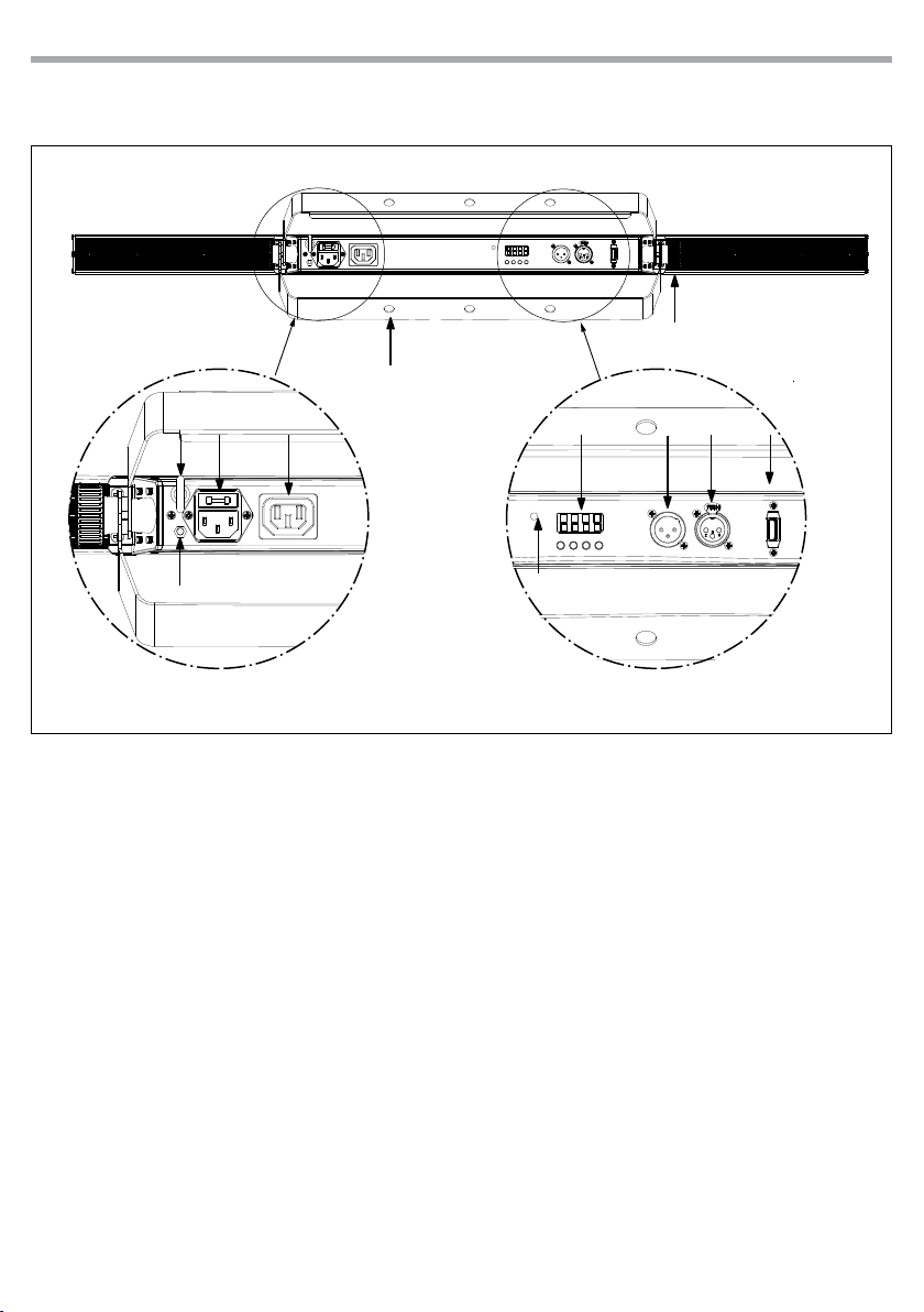
Fig.3
1
2

7
LUMIPIX9UHE
- 3 - FUNCTIONS AND SETTINGS
3.1 OPERATION
Connect the supplied main cable to a socket (100-240V 50/60Hz). Then the unit is ready for operation
and can be operated via a DMX controller or it independently performs its show program in succession.
To switch o, disconnect the mains plug from the socket. For a more convenient operation it is recom-
mended to connect the unit to a socket which can be switched on and o via a light switch.
3.2 BASIC
The LUMIPIX9UHE has a LED display and 4 buttons for access to the functions of the control panel (g.4).
MENU UP DOWN ENTER
Used to access the menu or
to return a previous menu
option
Button to select the values
in ascending order of the
function
Button to select the values
in descending order of the
function
Used to select and store the
current menu or conrm the
current function value or
option within a menu
Fig.4 - Functions of the buttons
MENU UP DOWN ENTER

LUMIPIX9UHE
8
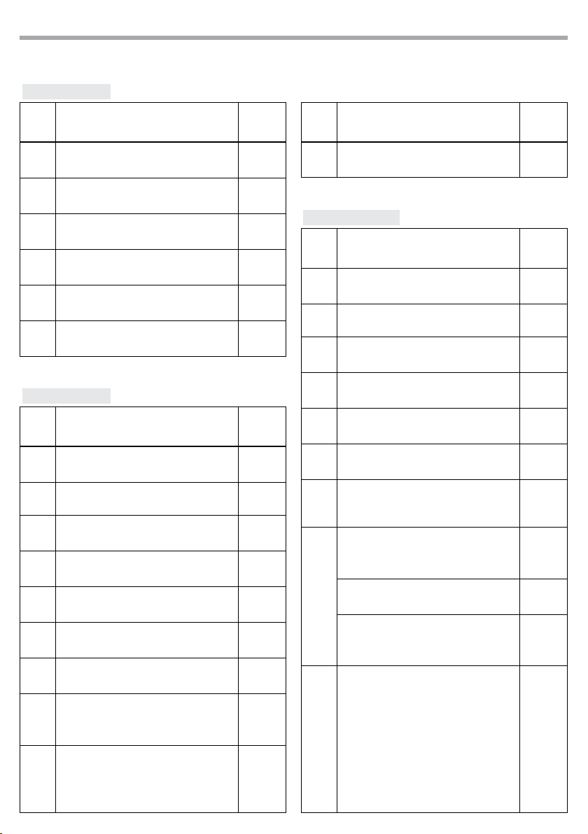
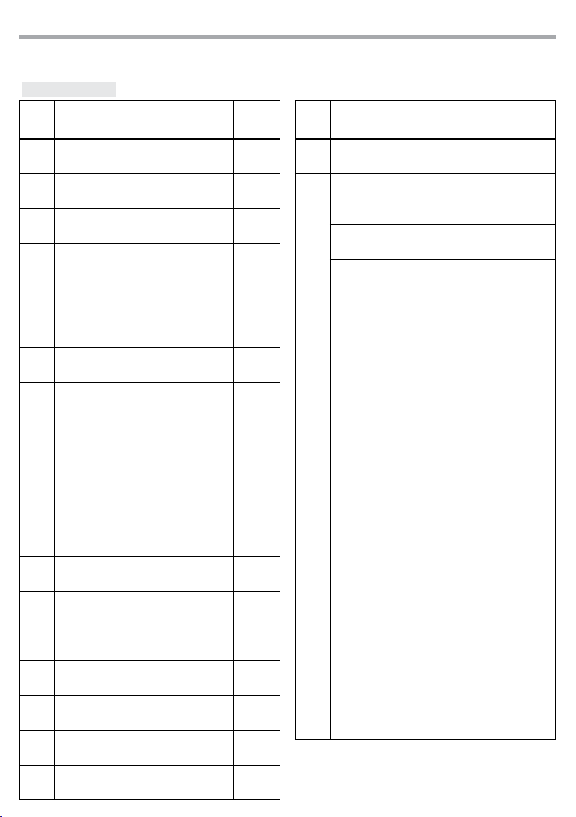
3.3 MENU STRUCTURE
MENU Remark
16 Channel ðValue (001-512) Default: 11 CH, d 1
29 Channel ðValue (001-512) Default: 11 CH, d 1
311 Channel ðValue (001-512) Default: 11 CH, d 1
418 Channel ðValue (001-512) Default: 11 CH, d 1
523 Channel ðValue (001-512) Default:11 CH, d 1
6C - - ð C 1 Default: C 63
C 2
C 3
C 4
... ...
C 62
C 63
7P - - ðP 1 Default: P1
P 2
P 3
... ...
P 12
P 13
P 14
8S - - ðValue (001-100) Default: S100
9Snd ð
10 SenS ðValue (001-100) Default:80
11 U - - ðValue r (000 -255) Default: RGBAWP=255
Value g(000 -255)
Value b(000 -255)
Value A(000 -255)
Value W(000-255)
Value P(000 -255)

9
LUMIPIX9UHE
3.4 AUTO SHOW
This xture has a built-in automatic program. To access this, please see the below instructions:
• Press the button MENU so many times until shows P--, then press the button ENTER.
• Using UP/DOWN button, select one of the programs P1 - P14.
• Press the button ENTER to conrm.
• Press the button MENU until S-- appears on the display.
• Use the button UP/DOWN to select the auto programs speed S1 - S100 (slow-fast).
• Press the button ENTER save the setting.
• Press the MENU button to go back or to meet the waiting time to exit the setup menu.
3.5 STATIC COLOR
This xture has the ability to accept custom static color settings. Access these chases via the control panel
on the back of the xture.
• Press the button MENU so many times until shows C--, then press the button ENTER.
• Using UP/DOWN button, select one of the programs C1 - C63.
• Press the button ENTER to conrm.
• Press the MENU button to go back or to meet the waiting time to exit the setup menu.
3.6 SOUND MODE
In music mode, the LUMIPIX9UHE can be controlled by music with a clear rhythm in the bass range. If the
music control should not work optimally, increase the volume or reduce the distance of the sound source.
• Press the button MENU so many times until the display shows Snd.
• Press the button ENTER to conrm.
• You can set the microphone sensitivity pressing the button MENU so many times until the display show
Sens.
• Using the button UP/DOWN, select the desired value sensitivity (slow-fast) u0 - u100.
• Press the button ENTER to conrm.
3.7 MANUAL COLOR
This mode allows to combine the colors red, green, blue amber white and purple (r, g, b, A, W, P).
• Press the button MENU so many times until the display shows [U--], then press the button ENTER.
• Select the color r, g, b, A, W, P through the buttons UP/DOWN.
12 dIM ðOFF Default: OFF
dIM1
dIM2
dIM3
13 SET ðOn Default: ON
OFF
14 TEMP ð60

LUMIPIX9UHE
10
• Press the button ENTER to conrm.
• Using UP/DOWN button, select the desired color value 000 - 255.
• Press ENTER button to continue to the next color.
• Continue until the desired mix is obtained.
• Press the MENU button to go back or to meet the waiting time to exit the setup menu.
3.8 MASTER/SLAVE MODE
This mode will allow you to link up the units together without a controller. Choose a unit to function as the
Master. The unit must be the rst unit in line; other units will work as slave.
• Use standard DMX cables to daisy chain your units together via the DMX connector on the rear of the
units. For longer cable runs we suggest a terminator at the last xture (see page 13).
• Use any one of the standalone modes for the master unit.
• Set the slaves to the same DMX modes.
3.9 LINKING
1. Connect the DMX OUT of the master unit via 3-pole XLR cable to the DMX IN of the rst slave unit.
2. Connect the DMX OUT of the rst slave unit to the DMX IN of the second slave unit, etc. until all units
are connected in a chain.
3.10 DMX MODE
• Press the button MENU so many times until shows, 6CH, 9 CH, 11 CH, 18 CH, 23CH and press the button
ENTER to conrm.
• Press the button UP/DOWN to select the desired DMX address d1 - d512. Press and hold to scroll quickly.
Press ENTER button to store.
The tables on page 14 indicate the operating mode and DMX value. The LUMIPIX9UHE is equipped with
3 pole XLR connections.
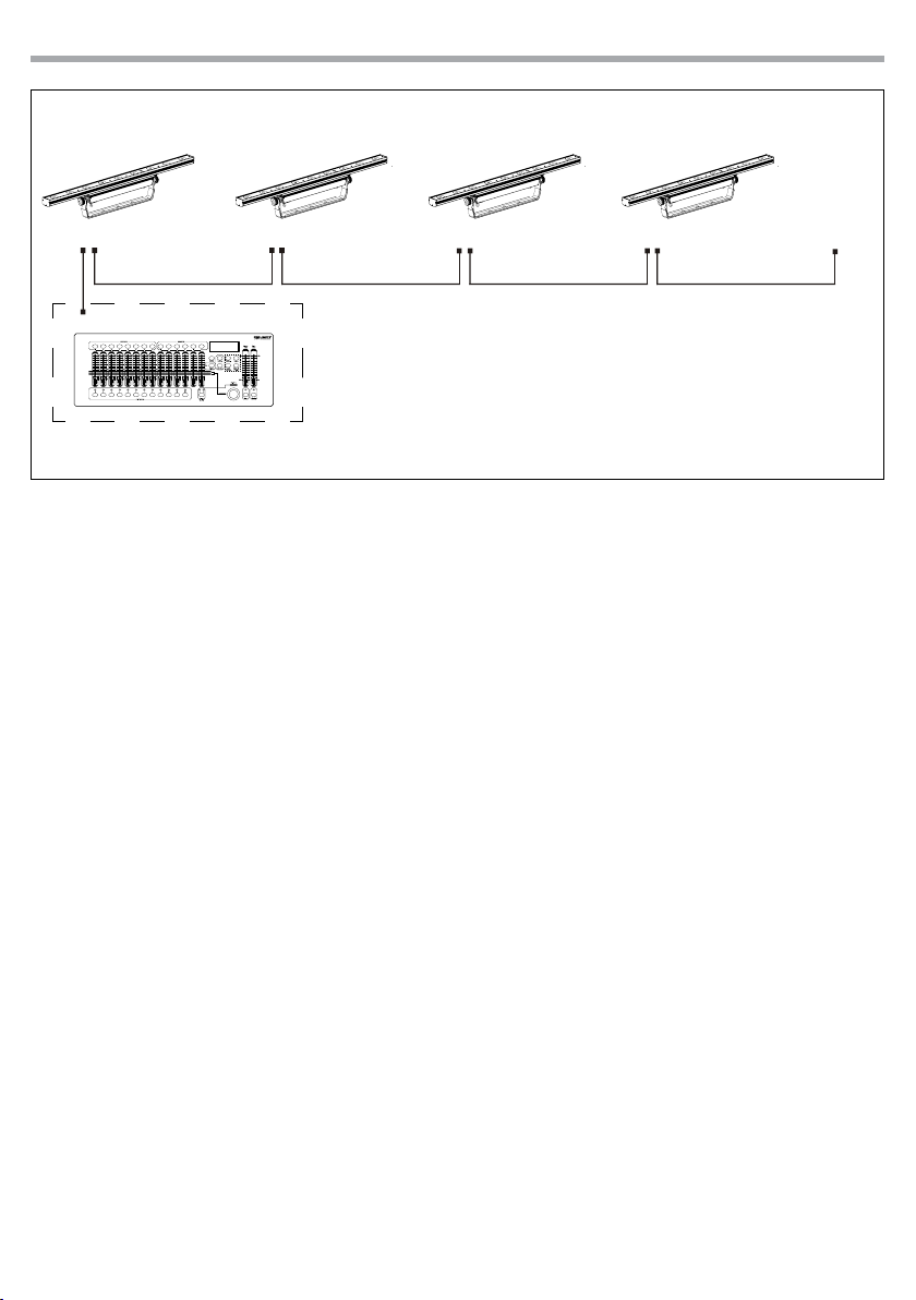
3.11 DMX ADDRESSING
To able to operate the LUMIPIX9UHE with a light controller, adjust the DMX start address for the rst a
DMX channel. If e. g. address 33 on the controller is provided for controlling the function of the rst DMX
channel, adjust the start address 33 on the LUMIPIX9UHE. The other functions of the light eect panel are
then automatically assigned to the following addresses.
An example with the start address 33 is shown below:
Number of
DMX channels
Start address
(example)
DMX Address
occupied
Next possible start
address for unit No. 1
Next possible start
address for unit No. 2
Next possible start
address for unit No. 3
6 33 33-38 39 45 51
9 33 33-41 42 51 60
11 33 33-43 44 55 66
18 33 33-52 51 69 87
23 33 33-43 56 79 102
11
LUMIPIX9UHE
DMX Address: 60DMX Address: 42DMX Address: 33 DMX Address: 51
Fig.5 - Example 9 DMX channels conguration
. . . . . . . . . . . .
DMX512 Controller

LUMIPIX9UHE
12
Fig.6
Fig.7
3.12 CONNECTION OF THE DMX LINE
DMX connection employs standard XLR connectors. Use shielded pair-twisted cables with 120Ω imped-
ance and low capacity.
The following diagram shows the connection mode:
ATTENTION
The screened parts of the cable (sleeve) must never be connected to the system’s earth, as this would
cause faulty xture and controller operation.
Over long runs can be necessary to insert a DMX level matching amplier.
For those connections the use of balanced microphone cable is not recommended because it cannot
transmit control DMX data reliably.
• Connect the controller DMX input to the DMX output of the rst unit.
• Connect the DMX output to the DMX input of the following unit. Connect again the output to the input
of the following unit until all the units are connected in chain.
• When the signal cable has to run longer distance is recommended to insert a DMX termination on the
last unit.
3.13 CONSTRUCTION OF THE DMX TERMINATION
The termination avoids the risk of DMX 512 signals being reected back along the cable when they reach-
es the end of the line: under certain conditions and with certain cable lengths, this could cause them to
cancel the original signals.
The termination is prepared by soldering a 120Ω 1/4 W resistor between pins 2 and 3 of the 3-pin male XLR
connector, as shown in gure.
DMX - OUTPUT
XLR socket
DMX - INPUT
XLR plug
Pin1 : GND - Shield
Pin2 : - Negative
Pin3 : + Positive
Example:
3 pin XLR connector
13
LUMIPIX9UHE
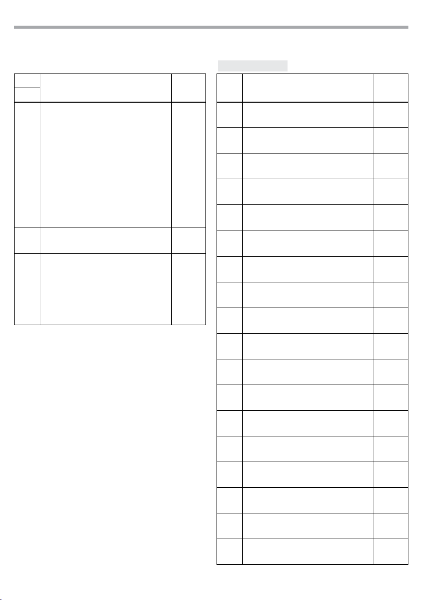
3.14 DMX CONTROL
6 CHANNELS
MODE FUNCTION DMX
Value
6 Ch
1RED 1
0~100% 000 - 255
2GREEN 1
0~100% 000 - 255
3BLUE 1
0~100% 000 - 255
4Amber
0~100% 000 - 255
5White
0~100% 000 - 255
6Purple
0~100% 000 - 255
9 CHANNELS
MODE FUNCTION DMX
Value
9 Ch
1RED
0~100% 000 - 255
2GREEN
0~100% 000 - 255
3BLUE
0~100% 000 - 255
4Amber
0~100% 000 - 255
5White
0~100% 000 - 255
6Purple
0~100% 000 - 255
7Dimmer
0~100% 000 - 255
8
Strobe
No Function
Strobe slow to fast
000 - 255
016 - 255
9
Dimmer Speed Mode
Preset dimmer speed from display menu
Dimmer speed mode o
Dimmer speed mode1 (fast speed)
000 - 051
052 - 101
102 - 152
MODE FUNCTION DMX
Value
9 Ch
9Dimmer speed mode2 (middle speed)
Dimmer speed mode3 (slow speed)
153 - 203
204 - 255
11 CHANNELS
MODE FUNCTION DMX
Value
11 Ch
1RED
0~100% 000 - 255
2GREEN
0~100% 000 - 255
3BLUE
0~100% 000 - 255
4Amber
0~100% 000 - 255
5White
0~100% 000 - 255
6Purple
0~100% 000 - 255
7
Color Macros
No Function
Color Macro
000-015
016-255
8
Strobe
No Function
Strobe slow to fast
000 - 015
016 - 255
RGB/Auto Speed
Speed slow to fast 000 - 255
Sound Sensitivity
Sound sensitivity OFF
Control the sound sensitivity
000 - 010
011 - 255
9
RGB/Auto Program
No Function
Pulse eect 0%-100%
Pulse eect 100%-0%
Pulse eect 100%-0%-100%
Auto program 2
Auto program 3
Auto program 4
Auto program 5
000 - 031
032 - 063
064 - 095
096 - 114
115 - 122
123 - 130
131 - 138
139 - 146
LUMIPIX9UHE
14
MODE FUNCTION DMX
Value
11 Ch
9
Auto program 6
Auto program 7
Auto program 8
Auto program 9
Auto program 10
Auto program 11
Auto program 12
Auto program 13
Auto program 14
Auto program 1
Sound program
147 - 154
155 - 162
163 - 170
171 - 178
179 - 186
187 - 194
195 - 202
203 - 210
211 - 218
219 - 226
227 - 255
10 Dimmer
0~100% 000 - 255
11
Dimmer Mode
Preset dimmer speed from display menu
Dimmer speed mode o
Dimmer speed mode1 (fast speed)
Dimmer speed mode2 (middle speed)
Dimmer speed mode3 (slow speed)
000 - 051
052 - 101
102 - 152
153 - 203
204 - 255
18 CHANNELS
MODE FUNCTION DMX
Value
18 Ch
1RED 1
0~100% 000 - 255
2GREEN 1
0~100% 000 - 255
3BLUE 1
0~100% 000 - 255
4Amber1
0~100% 000 - 255
5White1
0~100% 000 - 255
6Purple1
0~100% 000 - 255
7RED 2
0~100% 000 - 255
8GREEN 2
0~100% 000 - 255
9BLUE 2
0~100% 000 - 255
10 Amber2
0~100% 000 - 255
11 White2
0~100% 000 - 255
12 Purple2
0~100% 000 - 255
13 RED 3
0~100% 000 - 255
14 GREEN 3
0~100% 000 - 255
15 BLUE 3
0~100% 000 - 255
16 Amber3
0~100% 000 - 255
17 White3
0~100% 000 - 255
18 Purple3
0~100% 000 - 255
15
LUMIPIX9UHE
23 CHANNELS
MODE FUNCTION DMX
Value
23 Ch
1RED 1
0~100% 000 - 255
2GREEN 1
0~100% 000 - 255
3BLUE 1
0~100% 000 - 255
4Amber1
0~100% 000 - 255
5White1
0~100% 000 - 255
6Purple1
0~100% 000 - 255
7RED 2
0~100% 000 - 255
8GREEN 2
0~100% 000 - 255
9BLUE 2
0~100% 000 - 255
10 Amber2
0~100% 000 - 255
11 White2
0~100% 000 - 255
12 Purple2
0~100% 000 - 255
13 RED 3
0~100% 000 - 255
14 GREEN 3
0~100% 000 - 255
15 BLUE 3
0~100% 000 - 255
16 Amber3
0~100% 000 - 255
17 White3
0~100% 000 - 255
18 Purple3
0~100% 000 - 255
19 Color Macros
No Function 000 - 014
MODE FUNCTION DMX
Value
23 Ch
19 Color Macro 015 - 255
20
Strobe
No Function
Strobe slow to fast
000 - 015
016 - 255
RGB/Auto Speed
Speed slow to fast 000 - 255
Sound Sensitivity
Sound sensitivity OFF
Control the sound sensitivity
000 - 010
011 - 255
21
RGB/Auto Program
No Function
Pulse eect 0%-100%
Pulse eect 100%-0%
Pulse eect 100%-0%-100%
Auto program 2
Auto program 3
Auto program 4
Auto program 5
Auto program 6
Auto program 7
Auto program 8
Auto program 9
Auto program 10
Auto program 11
Auto program 12
Auto program 13
Auto program 14
Auto program 1
Sound program
000 - 031
032 - 063
064 - 095
096 - 114
115 - 122
123 - 130
131 - 138
139 - 146
147 - 154
155 - 162
163 - 170
171 - 178
179 - 186
187 - 194
195 - 202
203 - 210
211 - 218
219 - 226
227 - 255
22 Dimmer
0~100% 000 - 255
23
Dimmer Mode
Preset dimmer speed from display menu
Dimmer speed mode o
Dimmer speed mode1 (fast speed)
Dimmer speed mode2 (middle speed)
Dimmer speed mode3 (slow speed)
000 - 051
052 - 101
102 - 152
153 - 203
204 - 255
LUMIPIX9UHE
16
Manual Color Control
To choose a specic color with the controller:
1. Press MANUAL on the controller.
2. Press any number between 0-9 to choose your color.
To manually control the RGB percentage:
3. Press MANUAL on the controller.
4. Press R, G, B, A, W, P to choose your color.
5. Press + or – to increase or decrease the percentage of each color.
Miscellaneous Operation
To adjust the strobe rate of the program:
1. Press STROBE on the controller.
2. Press + or – to increase or decrease the strobe rate.
3. Press STROBE again to turn o the strobe.
To change the switching eect of the program:
• Press FADE/SNAP on the controller.
3.15 DIMMER
• Enter in Dimmer mode to select specic dimming curve, press the button MENU so many times until
shows dIM, and press the button ENTER to conrm.
• Press the button UP/DOWN to select OFF - dIM1 - dIM2 - dIM3.
• Press ENTER button to store.
• Press the MENU button to go back or to meet the waiting time to exit the setup menu.
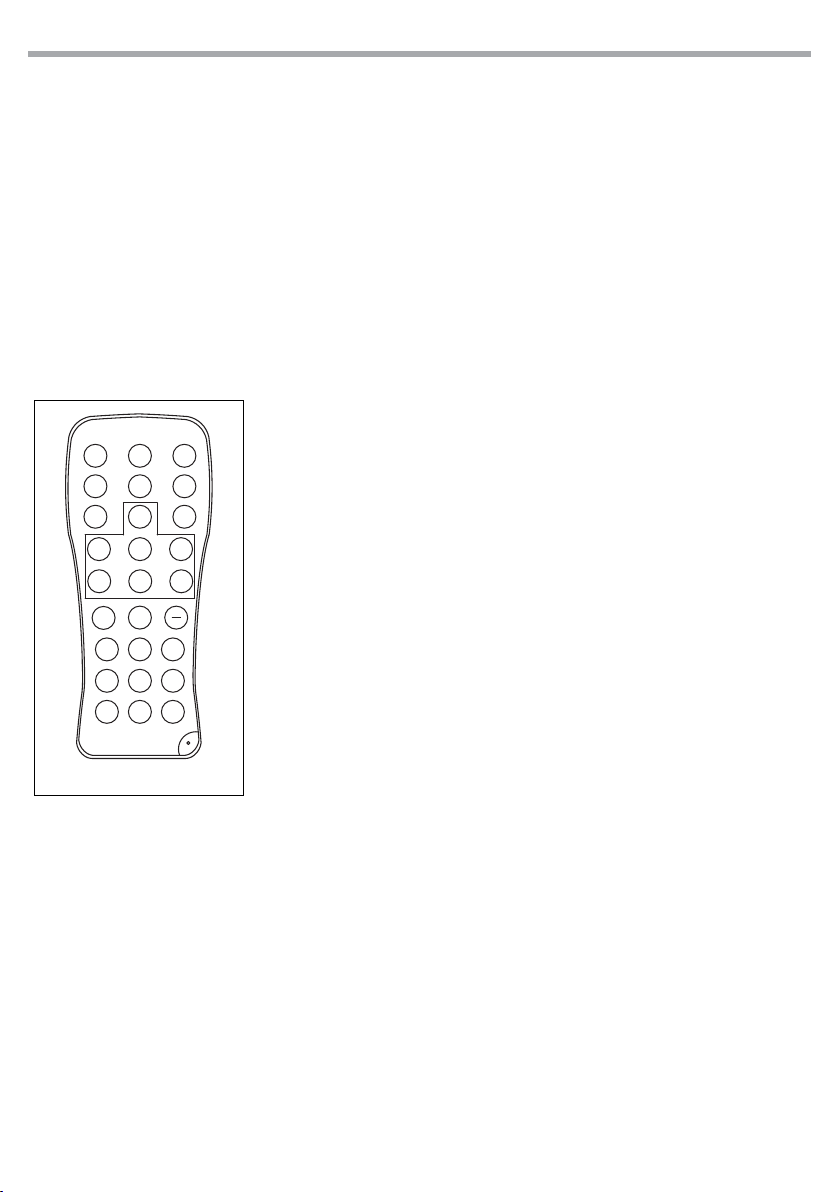
3.16 OPERATION THROUGH THE IRC CONTROLLER
To control the LUMIPIX9UHE with the infrared remote control:
• Press the button MENU repeatedly until SET, then press button ENTER to conrm.
• Using UP/DOWN button to select On or OFF to enable or disable the infrared remote control.
• Press the button ENTER to conrm the chose.
NOTE - Make sure to point the controller directly at the receiver on the product.
Automatic Mode
Automatic Mode will enable you to run the automatic programs on the
product.
To turn on Automatic Mode:
1. Press AUTO on the controller.
2. Press + or – to choose between the dierent auto programs.
To adjust the speed of the automatic program:
3. Press SPEED on the controller.
4. Press %.
5. Press + or – to either increase or decrease the speed of the program.
Sound Active Mode
Sound Active Mode will enable the product to respond to the music.
To turn on Sound Active mode:
1. Press SOUND on the controller.
To adjust sound sensitivity in Sound Active mode:
1. Press SENSITIVITY on the controller.
2. Press %.
3. Press + or – to either increase or decrease sound sensitivity.
Fig.8
IRC REMOTE
BLACK
OUT AUTO
STROBE SPEED
SOUND
SENSI-
TIVITY
%MANUAL FADE
RG B
+0
123
456
7 8 9
AUV W

17
LUMIPIX9UHE
• Fade will slowly switch the eect. Snap will rapidly switch the eect.
To black out the lights:
• Press BLACK OUT on the controller.
• This will turn o all the lights until the button is pressed again.
NOTE - The controller will not respond to any inputs when Black Out is activated. If the remote does not
respond when a button is pressed, try pressing BLACK OUT. You may have inadvertently activated BLACK
OUT.

LUMIPIX9UHE
18
- 4 - MAINTENANCE
4.1 MAINTENANCE AND CLEANING THE UNIT
• Make sure the area below the installation place is free from unwanted persons during setup.
• Switch o the unit, unplug the main cable and wait until the unit has cooled down.
• All screws used for installing the device and any of its parts should be tightly fastened and should not
be corroded.
• Housings, xations and installation spots (ceiling, trusses, suspensions) should be totally free from any
deformation.
• The main cables must be in impeccable condition and should be replaced immediately even when a
small problem is detected.
• It is recommended to clean the front at regular intervals, from impurities caused by dust, smoke, or
other particles to ensure that the light is radiated at maximum brightness. For cleaning, disconnect the
main plug from the socket. Use a soft, clean cloth moistened with a mild detergent. Then carefully wipe
the part dry. For cleaning other housing parts use only a soft, clean cloth. Never use a liquid, it might
penetrate the unit and cause damage to it.
4.2 FUSE REPLACEMENT
1. Disconnect this product from the power outlet.
2. Remove the safety cap by a screwdriver.
3. Replace the blown fuse with a fuse of the exact same type and rating (T2A/250V).
4. Install the safety cap, and reconnect power.
4.3 TROUBLESHOOTING
Fig.9
Problems Possible causes Checks and remedies
Fixture does not light up
• No mains supply
• Dimmer fader set to 0
• All color faders set to 0
• Faulty LED
• Faulty LED board
• Check the power supply voltage
• Increase the value of the dimmer channels
• Increase the value of the color channels
• Replace the LED board
• Replace the LED board
General low light intensity • Dirty lens assembly
• Misaligned lens assembly
• Clean the xture regularly
• Install lens assembly properly
Fixture does not power up
• No power
• Loose or damaged power cord
• Faulty internal power supply
• Check for power on power outlet
• Check power cord
• Replace internal power supply
Fixture does not respond to DMX
• Wrong DMX addressing
• Damaged DMX cables
• Bouncing signals
• Check control panel and unit addressing
• Check DMX cables
• Install terminator as suggested
Contact an authorized service center in case of technical problems or not reported in the table can not be
resolved by the procedure given in the table.
This manual suits for next models
1
Table of contents
Languages:
Other Tribe Dj Equipment manuals

Tribe
Tribe MINIVERSAPAR User manual

Tribe
Tribe JETBEAM1 User manual

Tribe
Tribe SUNRISE2 User manual

Tribe
Tribe FLATPAR3Q User manual

Tribe
Tribe LUMIPAR12UAW User manual

Tribe
Tribe PIXROLL10UTRI User manual

Tribe
Tribe LUMIPAR 12UQ PRO User manual

Tribe
Tribe JETSPOT1 User manual

Tribe
Tribe LUMIPAR12UH3P User manual

Tribe
Tribe PROLIGHTS SMARTBATTENQ User manual


