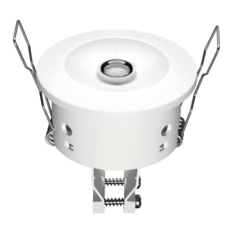
Tridonic DALI XC G3 CWM 30 DA2 User manual

DALI XC G3 CWM 30 DA2
article number/Artikelnummer: 28002877
02/19-xxx-0 We reserve the right to make technical changes without prior notice.
Wiring diagram / Verdrahtungsdiagramm / Schéma de branchement / Schema elettrico / Diagrama de cableado / Kopplingsschema
0.2 – 1.5 mm²
8.5 – 9.5 mm
solid/fine-stranded
eindrähtig/feindrähtig
monobrin/fil fin
a filo unico/a fili sottili
monofilar/hilo fino
entrådig/fintrådig
DA
DA
T4
T3
T2
T1
COM
max. 50 cm
Leitungslänge an Eingängen T1 – T4 und COM
Line length at inputs T1–T4 and COM
Longueur de ligne aux entrées T1 – T4 et COM
Lunghezza della linea alle entrate T1-T4 e COM
Longitud de la línea en las entradas T1 – T4 y COM
47.7
14.6
28.2
28.2
MSensor
DALI
PS
Multi-Master-
Application-Controller
L
N
LED Driver LED Driver
DALI XC
DALI XC
9.5 – 22.5 V
DA
DA
DALI XC G3
CWM 30 DA2
DA
DA
T4
T3
T2
T1
COM
DALI XC G3
CWM 30 DA2 Ledningslängd vid ingångar T1 – T4 och COM
Dimensional drawing / Maßzeichnung / Schéma coté / Disegno dimensionale /
Dibujo dimensional / Måttritning
DALI Input controller with 4 independent inputs for floating contacts.
Technical Data
Supply via DALI
Supply voltage19.5 – 22.5 V
Current consumption max. 10 mA
Input 4 momentary switches or relais
Ambient temperature ta 0 ... +60 °C
tc 65 °C
Storage temperature -25 ... +60 °C
Turn on time �6 s
Humidity 20 ... 90 % (non-condensing)
Type of protection IP20
Mounting Mounting box 60 x 61 mm (øx D)
Casing material Lexan 923
Casing colour Light grey, similar to RAL 7035
Dimensions L x W x H 47.7 x 28.2 x 14.6 mm
1Uin acc. IEC 62386-101.
UK
DALI Eingangs-Controller mit 4 unabhängigen Eingängen für potenzialfreie
Kontakte.
Technische Daten
Versorgung über DALI
Versorgungsspannung19,5–22,5 V
Stromverbrauch max. 10 mA
Eingang 4 Taster oder Relais
Umgebungstemperatur ta 0 ... +60 °C
tc 65 °C
Lagertemperatur -25 ... +60 °C
Einschaltzeit �6 s
Luftfeuchtigkeit 20 ... 90 % (nicht kondensierend)
Schutzart IP20
Montage Unterputzdose 60 × 61 mm (ø × T)
Gehäusematerial Lexan 923
Gehäusefarbe Hellgrau, ähnlich RAL 7035
Abmessungen L × B × H 47,7 × 28,2 × 14,6 mm
1Uin gem. IEC 62386-101.
Sicherheitshinweise
• Die Installation dieses Gerätes darf nur durch ausgewiesenes
Fachpersonal erfolgen.
• Vor dem Arbeiten am Gerät muss die Stromversorgung ausgeschaltet werden.
• Die geltenden Sicherheits- und Unfallverhütungsvorschriften sind zu beachten.
Einsatzbereich
Das Gerät darf nur
• für den bestimmungsgemäßen Einsatz verwendet werden.
• fest in trockener und sauberer Umgebung installiert werden.
• so installiert werden, dass ein Zugriff nur mit Werkzeug möglich ist.
D
Installation
• Das Gerät kann in die Unterputzdose für den Taster eingesetzt werden.
• Das Gerät darf nicht an das Stromnetz angeschlossen werden.
Die Stromversorgung erfolgt direkt über die DALI-Signalleitung.
• Die Taster werden direkt am Gerät angeschlossen (potenzialfreie Kontakte) und
dürfen nicht an das Stromnetz angeschlossen werden.
• DALI-Signale sind nicht SELV. Daher gelten dieselben Vorgehensweisen wie bei
der Netzspannung.
• Es darf nur ein Taster je Geräteausgang angeschlossen werden.
• Es können mehrere Geräte in einem DALI-Netzwerk verwendet werden.
Installation
• Device can be inserted into the mounting box for the momentary switch.
• Device must not be connected to the mains. It is supplied directly via the DALI
signal line.
• The momentary switches are connected directly to the device (potential free
contacts) and must not be connected to the mains.
• DALI signals are not SELV. Therefore the same procedures should be applied as
working with mains voltage.
• Only one momentary switch each device output.
• Multiple devices can be used on the same DALI network.
INSTALLATION
Safety instructions
• Installation of this device may only be carried out by specialist staff who have
provided proof of their skills.
• The power supply must be switched off before handling the device.
• The relevant safety and accident prevention regulations must be observed.
Areas of application
The device may only
• be used for the applications specified.
• be used for safe installation in dry, clean environment.
• be installed in such a way that access is only possible using a tool.

DALI XC G3 CWM 30 DA2
article number/Artikelnummer: 28002877
02/19-xxx-0 We reserve the right to make technical changes without prior notice.
Avvertenze di sicurezza
• L‘installazione di questo apparecchio può avvenire solo a cura di
personale specializzato istruito.
• Prima dei lavori all‘apparecchio deve essere spenta l‘alimentazione elettrica.
• Devono essere rispettate le norme di sicurezza e antinfortunistiche vigenti.
Campo d‘impiego
L‘apparecchio può solo
• essere impiegato per l‘impiego secondo le disposizioni.
• essere installato in modo fisso in un ambiente asciutto e pulito.
• essere installato in modo che sia possibile accedervi solo con degli strumenti.
I
Indicaciones de seguridad
• La instalación de este dispositivo sólo puede llevarse a cabo
por personal cualificado.
• Antes de trabajar en el dispositivo, la fuente de alimentación debe estar apagada.
• Se deben respetar las normas de seguridad y de prevención de accidentes vigentes.
Ámbito de aplicación
El aparato sólo podrá
• ser utilizado para el uso previsto.
• instalarse en ambiente seco y limpio.
• ser instalado de manera que el acceso solo sea posible con una herramienta.
ESP
Säkerhetsanvisningar
• Installation av denna enhet får endast utföras av utbildad och kompetent personal.
• Innan arbeten genomförs på enheten måste strömmen kopplas från.
• Gällande direktiv för säkerhet och förebyggande av olycksfall ska följas.
Användningsområde
Enheten får endast
• användas för de angivna användningsområdena.
• användas för säker installation i en torr, ren miljö.
• installeras så att den endast kan nås med hjälp av ett verktyg.
S
Domaine d‘application
L‘appareil doit uniquement
• être utilisé pour une utilisation conforme.
• être installé de façon fixe dans un environnement sec et propre.
• être installé de façon à ce qu‘un accès soit possible uniquement avec des outils.
Consignes de sécurité
• L‘installation de cet appareil doit uniquement être effectué par des membres
du personnel qualifiés.
• Avant d‘effectuer des travaux sur l‘appareil, l‘alimentation électrique doit être désactivée.
• Les dispositions de sécurité et de prévention des accidents applicables doivent être respec-
tées.
F
Unité de contrôle d‘entrée DALI avec 4 entrées indépendantes pour des
contacts libres de potentiel.
Caractéristiques
Alimentation par DALI
Tension d’alimentation19,5 – 22,5 V
Consommation électrique max. 10 mA
Entrée 4 boutons-poussoir ou relais
Température ambiante ta 0 ... +60 °C
tc 65 °C
Température de stockage -25 ... +60 °C
Temps d’allumage �6 s
Humidité 20 ... 90 % (sans condensation)
Type de protection IP20
Montage Boîtier d’encastrement 60 x 61 mm (ø x p)
Matériau du boîtier Lexan 923
Couleur du boîtier Gris clair, similaire à RAL 7035
Dimensions L x l x h 47,7 x 28,2 x 14,6 mm
1Uin acc. IEC 62386-101.
Controlador de entrada DALI con 4 entradas independientes para contactos
flotantes.
Datos técnicos
Alimentación DALI
Tensión nominal de alimentación19,5 – 22,5 V
Consumo de corriente Máx. 10 mA
Entrada 4 interruptores o relés
Temperatura ambiente ta 0 ... +60 °C
tc 65 °C
Temperatura de almacenamiento –25 ... +60 °C
Tiempo de activación �6 s
Humedad 20 ... 90 % (sin condensación)
Tipo de protección IP20
Montaje Caja de montaje 60 x 61 mm (ø x Pr)
Material de carcasa Lexan 923
Color de carcasa Gris claro, similar a RAL 7035
Dimensiones larg. x an. x al. 47,7 x 28,2 x 14,6 mm
1Uin según IEC 62386-101.
Controller d‘ingresso DALI con 4 ingressi indipendenti per contatti liberi da
potenziale.
Dati tecnici
Alimentazione tramite DALI
Tensione di alimentazione19,5 – 22,5 V
Corrente assorbita max. 10 mA
Ingresso 4 pulsanti o relè
Temperatura ambiente ta 0 ... +60 °C
tc 65 °C
Temperatura di stoccaggio -25 ... +60 °C
Tempo di accensione �6 s
Umidità 20 ... 90% (senza formazione di condensa)
Tipo di protezione IP20
Montaggio Scatola di montaggio 60 x 61 mm (ø x P)
Materiale custodia Lexan 923
Colore custodia Grigio chiaro, equivalente a RAL 7035
Dimensioni L x P x A 47,7 x 28,2 x 14,6 mm
1Uin a norma IEC 62386-101.
DALI-ingångsstyrenhet med 4 oberoende ingångar för flytande kontakter.
Tekniska data
Försörjning via DALI
Matningsspänning19,5–22,5 V
Strömförbrukning max. 10 mA
Ingång 4 tryckknappar eller reläer
Omgivningstemperatur ta 0 ... +60 °C
tc 65 °C
Förvaringstemperatur –25 ... +60 °C
Tillslagstid �6 s
Luftfuktighet 20 ... 90 % (icke-kondenserande)
Typ av skydd IP20
Montering Monteringsbox 60 x 61 mm (ø x D)
Höljets material Lexan 923
Höljets färg Ljusgrå, liknande RAL 7035
Mått L x B x H 47,7 x 28,2 x 14,6 mm
1Uin enligt IEC 62386-101.
INSTALLATION
Installationsanvisningar
• Enheten kan sättas in i monteringsboxen för tryckknappen.
• Enheten får inte vara ansluten till elnätet.
Den försörjs direkt via DALI-signalledningen.
• Tryckknapparna ansluts direkt till enheten (potentialfria kontakter) och får inte
anslutas till elnätet.
• DALI-signaler är inte SELV. Därför bör samma förfaranden tillämpas som vid
arbete med nätspänning.
• Endast en tryckknapp för varje enhetsutgång.
• Flera enheter kan användas på samma DALI-nätverk.
Instructions pour l’installation
• L’appareil peut être inséré dans le boîtier d’encastrement pour le bouton-
poussoir.
• L’appareil ne doit pas être branché au secteur. Il est alimenté directement via la
ligne de signal DALI.
• Les boutons-poussoir sont reliés directement à l’appareil (contacts libres de
potentiel) et ne doivent pas être branchés au secteur.
• Les signaux DALI ne correspondent pas à une TBTS. Les mêmes procédures
doivent donc être appliquées que lors d‘une utilisation sous tension secteur.
• Un seul bouton-poussoir par sortie de l’appareil.
• Plusieurs appareils peuvent être utilisés sur le même réseau DALI.
Installazione
• L‘apparecchio può essere inserito nella scatola di montaggio del pulsante.
• L‘apparecchio non deve essere collegato alla rete elettrica poiché è alimentato
direttamente dalla linea di segnale DALI.
• I pulsanti sono collegati direttamente all‘apparecchio (contatti a potenziale zero)
e non devono essere collegati alla rete elettrica.
• I segnali DALI sono diversi da SELV. Pertanto è necessario applicare le stesse
procedure utilizzate per la tensione di rete.
• Un solo pulsante per ciascuna uscita apparecchio.
• È possibile utilizzare più apparecchi sulla stessa rete DALI.
Instalación
• El dispositivo puede insertarse en la caja de montaje del interruptor.
• El dispositivo no debe conectarse a la red eléctrica. Su alimentación se
proporciona directamente mediante la línea de señal DALI.
• Los interruptores están conectados directamente al dispositivo (contactos libres
de potencia) y no deben conectarse a la red eléctrica.
• Las señales DALI no son SELV. Por ello, deben aplicarse los mismos procesos al
trabajar con tensión de red.
• Solo un interruptor por cada salida de dispositivo.
• Pueden usarse varios dispositivos en la misma red DALI.
Other Tridonic Controllers manuals
Popular Controllers manuals by other brands
Siemens
Siemens SIMATIC S7-200 System manual
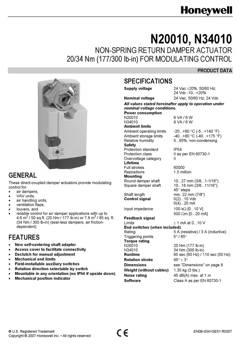
Honeywell
Honeywell N20010 manual
Compit
Compit SOLARCOMP 951 Installation and operating instructions
Rain Bird
Rain Bird WPX user manual
Endress+Hauser
Endress+Hauser Liquiline CM44 series installation instructions
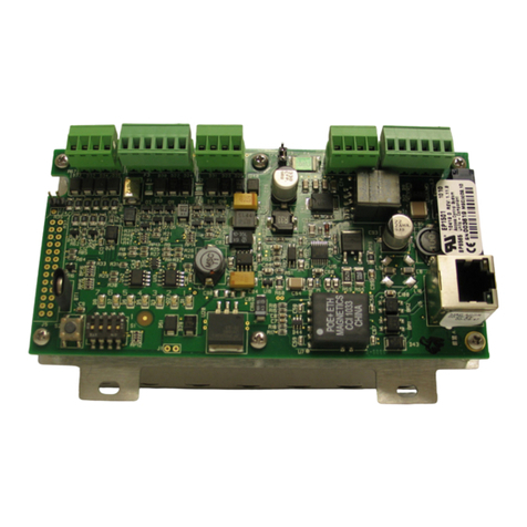
Honeywell
Honeywell PW6K1ICE Installation and configuration guide
