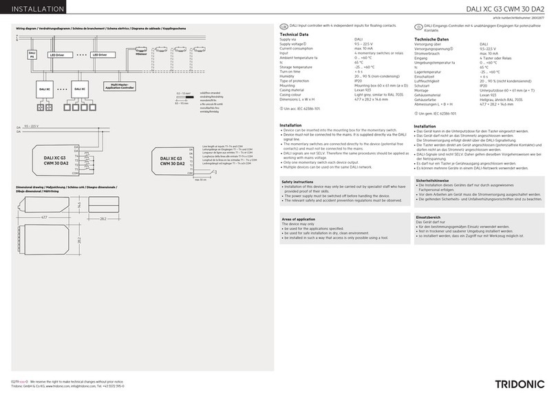
Tridonic luxCONTROL DaLI Msensor 5DPI 14 User manual

V052019
Ce produit doit être installé par une personne qualifiée.
S’assurer de la compatibilité des produits suivant son environnement.
La mise en œuvre de l’appareil doit se faire selon les règles de l’art. Nous déclinons toutes responsabilités et nous nous réservons le droit d'annuler la garantie du luminaire en
cas d’installation non conforme, ne respectant pas les préconisations, ou modifiant les caractéristiques de l'appareil. Conserver ce document pour toute utilité future.
EVA CENTRIC
Tension d'alimentation: 220-240V +/- 6%
Fréquence: 50/60Hz
CRI80 / CRI90 / TNW
NW: 4000k; CW: 5000K: WW: 3000K
EN60598-1 EN60598-2-1 EN 62471-RG0
EN61000-3-2 EN61000-3-3 EN55015 EN61547
NOTICE D'UTILISATION
Ce symbole indique que ce produit ne doit pas être mis au rebut avec les déchets ménagers classiques selon la législation européenne 2012/19/EU. Pour limiter les
risques pour l’environnement et la santé entraînés par le rejet non contrôlé des déchets et afin de promouvoir une réutilisation de ces matériaux, les produits
doivent être recyclés. Pour cela, utilisez les réseaux de collectes de votre région ou prenez contact avec votre revendeur.
Luminaire ne pouvant être recouvert
d’un matériau isolant thermique
Fixation du luminaire
Les modules LED ne sont pas remplaçables. En cas de défaillance le produit doit être changé sous réserve d'acceptation du fabricant.
Version 5P
1) Insérer câble d'alimentation électrique par le
trou prévu à cet effet puis effectuer les
branchements sur le connecteur rapide.
Pour le branchement électrique utiliser un câble
d'alimentation conforme 60227IEC 52/EN50525
0-75-1.5mm²
2) Vérifier branchements et refermer la languette.
Branchement réseau: Raccorder la phase et le neutre
sur le bornier.
Faux plafond
1) Accrocher le filin de sécurité sur
un support solide.
2) Effectuer les branchements
électriques. (ci-dessous)
3) Poser les encastrés sur
les porteurs du faux plafond
Languette de connexion
Version 3P
AVANT DE COMMENCER LES BRANCHEMENTS COUPER L'ALIMENTATION ELECTRIQUE
Le luminaire doit être installéà une hauteur supérieure de 2.35m du sol;
Pour utilisation en intérieur uniquement;
8 RUE JOHANNES BRAHMS
63200 RIOM FRANCE
Branchements électriques
Entretien et fin de vie
Maintenance du luminaire:
1) Couper l'alimentation électrique
2) Avec un tissu antistatique sec, dépoussiérer le diffuseur et l'enveloppe sans ouvrir
le produit. Ceci peut garantir un meilleur rendement et réduire la consommation du
luminaire.
Fin de vie:
1) Couper l'alimentation électrique.
2) Enlever le(s) luminaire(s) de son support de fixation
3) Rapprochez-vous de votre mairie pour localiser les centres de collectes
www.electraworld.fr

V012019
8 RUE JOHANNES BRAHMS
63200 RIOM FRANCE
INTERFACE DETECTION NON FOURNIE
Vérifier l'installation avant la mise en marche du système.
Un mauvais branchement sur le bornier d'alimentation endommagera le
ballast et les interfaces et annulera de ce fait la garantie du produit.
Fonction CORRIDOR : diminution de la lumière graduellement jusqu'à 10%
du flux lumineux.
Fonction PREAVIS : diminution de la lumière graduellement jusqu'à 10% du
flux lumineux et extinction du luminaire après 15 mins.
Spécifications modifiables via logiciel masterconfigurator.
DRIVER INTELLIGENT - TNW
NOTICE D'UTILISATION
Remarque importantes :
Tous les luminaires à gradations numérique équipés de driver "LCAI/LCA" sont livrés sur le mode fonction corridor, jamais éteint.
Fonction poussoir: Pour activer la fonction "bouton poussoir" appuyer à 5 reprises en l’espace de 3 secondes sur le bouton poussoir.
Fonction corridor: Pour re-activer le mode corridor/préavis appliquer une tension de 230V pendant 5 minutes sur la charge D1/D2 du bornier de
connexion.
Master configurator: Logiciel de programmation de scénarios DALI ou DSI permettant la configuration des ballasts/Driver via les interfaces DALI PS1
et DALI USB - téléchargement du logiciel sur www.tridonic.fr
VERIFIER LA COMPATIBILITE DES INTERFACES
Interface compatible
Schéma de montage DRIVER LCAI / LCA
Driver : compatible interface Dali, DSI, fonction
Corridor/préavis, poussoir, et détecteur présence/DSI/
DALI. Compatible langage KNX, LON et TCP/IP.
Support R2M sur demande (TRIDONIC)
Programmations de scénarios et réglages des Driver avec le
logiciel MASTER CONFIGURATOR via les interfaces DALI PS1
et DALI USB.
Fonction préavis / corridor - Driver LCAI
Interface détecteur déporté*
www.electraworld.fr

V012019
DRIVER INTELLIGENT - TNW
NOTICE D'UTILISATION
Interface détecteur déporté*
Détecteur déporté - à commander séparément.
Nombre d'élève max - Voir spécifications du
détecteur
Interface bouton poussoir*
Interface DALI/DSI*
*Interface non fourni
*Interface non fourni
*Interface non fourni
Interface détecteur BASIC DIM ILD
Fonction poussoir - à commander séparement.
Nombre d'élève max - Voir application
Interface Dali - à commander séparement.
Nombre d'élève max - Voir interface DALI/Aculateur.
Interface DSI - à commander séparement
Nombre d'élève max - Voir interface DSI
Alimenter le reseau DALI avec PS - nous consulter
DALI BEGA-SR2400TL+ DALI PS TNW-SR2400PS2
DALI BEGA-SR2300G2300TSDIM + DALI PS TNW-SR2400PS2

V122018
DRIVER INTELLIGENT - TNW
NOTICE D'UTILISATION
Interface détecteur BASIC DIM ILD
CENTRIC
• Interface DALI:
Gestions et scénarios programmables via interface DALI
Possibilité de commander le système via logiciel masterconfigurator et interfaces de
commande type écran de contrôle:
DALI x/e-touchPANEL 28000005 + DALIUSB & DALI PS1 (gestion de scénarios)
DALI TOUCHPANEL02 28000022 + DALIUSB & DALI PS1 (Sélection de 3 température
de couleur)
DALI TNW-SR2422K4CCTAC + DALI PS TNW-SR2400PS2
DALI TNW-SR2300G4CCTC + DALI PS TNW-SR2400PS2
• Interface Poussoir
Gestion simplifié via 2 boutons poussoirs :
Poussoir #1 Luminosité, variation intensité lumineuse,
Poussoir #2 CCT, variation température couleur avec 7 modes de
couleur prédéfinis. De 3000K à 6000K, borne CS.
ACCESSOIRES DE PROGRAMMATIONS:
Télécommande: Ref: « Tel GUYANE »
Commande simplifié BASIC "PROGILD"
Commande "PROGGUYANE"
Master configurator "DALIPS1" +
"DALIUSB"
Dimmable de 100% à 10% sans influence sur la température de couleur & l’IRC du module
LED.
Variation de température de couleur de 3000K à 6000K.
Système TRIDONIC LLE PREMIUM, commandés par interfaces DALI ou poussoirs.
INC2XLEDBEGM avec Détecteur « basic DIM ILD » TRIDONIC intégré au luminaire - fonction présenceet
de luminosité.
Luminaire maître équipé de 2 sorties permettant de gérer un décalage d’éclairement négatif entre le
canal 1 et canal 2. (consommation veille < 0.3W).
Référence Luminaire élève "INC2XLEDBEGA"
Luminaire maître livre avec 3 borniers 1x5P + 2x3P
Bornier 5P : Alimentation 220-240V & connexion au canal 1 (Relier les charges DA-2 et DA+3 aux
luminaires du canal 1).
Bornier 3P : Connexion canal 2 (Relier les charges DA-2 et DA+3 aux luminaires du canal 2).
Bornier 3P: Bouton poussoir (en option) - Alimenter le poussoir sur le bornier (NE PAS RELIER LA TERRE)
Luminaire Pilot

luxCONTROL
DALI MSensor 5DPI 14
Product Manual

c2 / 48
...

Table of Contents
c3 / 48
Table of Contents
1 Validity . . . . . . . . . . . . . . . . . . . . . . . . . . . . . . . . . . . . . . . . . . . . . . . . . . . . . . . . . . . . . . . . . . . . . . . . . . 5
1.1 Copyright . . . . . . . . . . . . . . . . . . . . . . . . . . . . . . . . . . . . . . . . . . . . . . . . . . . . . . . . . . . . . . . . . . . . . . . . . . . . . 5
1.2 Imprint . . . . . . . . . . . . . . . . . . . . . . . . . . . . . . . . . . . . . . . . . . . . . . . . . . . . . . . . . . . . . . . . . . . . . . . . . . . . . . . 5
2 Safety instructions . . . . . . . . . . . . . . . . . . . . . . . . . . . . . . . . . . . . . . . . . . . . . . . . . . . . . . . . . . . . . . . . 6
2.1 Intended use . . . . . . . . . . . . . . . . . . . . . . . . . . . . . . . . . . . . . . . . . . . . . . . . . . . . . . . . . . . . . . . . . . . . . . . . . . 6
2.2 Dangers associated with the operation of the system . . . . . . . . . . . . . . . . . . . . . . . . . . . . . . . . . . . . . . . . . . . 6
3 Description . . . . . . . . . . . . . . . . . . . . . . . . . . . . . . . . . . . . . . . . . . . . . . . . . . . . . . . . . . . . . . . . . . . . . . 8
4 Installation . . . . . . . . . . . . . . . . . . . . . . . . . . . . . . . . . . . . . . . . . . . . . . . . . . . . . . . . . . . . . . . . . . . . . . 10
5 Commissioning and settings . . . . . . . . . . . . . . . . . . . . . . . . . . . . . . . . . . . . . . . . . . . . . . . . . . . . . . 11
5.1 Group assignment by using masterCONFIGURATOR . . . . . . . . . . . . . . . . . . . . . . . . . . . . . . . . . . . . . . . . . 11
5.2 Replacing a faulty DALI MSensor V2.0 . . . . . . . . . . . . . . . . . . . . . . . . . . . . . . . . . . . . . . . . . . . . . . . . . . . . . 11
5.3 Replacing a faulty DALI MSensor (V1.7 or earlier) . . . . . . . . . . . . . . . . . . . . . . . . . . . . . . . . . . . . . . . . . . . . 11
6 Functions . . . . . . . . . . . . . . . . . . . . . . . . . . . . . . . . . . . . . . . . . . . . . . . . . . . . . . . . . . . . . . . . . . . . . . 12
6.1 Constant light control . . . . . . . . . . . . . . . . . . . . . . . . . . . . . . . . . . . . . . . . . . . . . . . . . . . . . . . . . . . . . . . . . . . 12
6.2 Presence control . . . . . . . . . . . . . . . . . . . . . . . . . . . . . . . . . . . . . . . . . . . . . . . . . . . . . . . . . . . . . . . . . . . . . . 18
6.3 Remote control . . . . . . . . . . . . . . . . . . . . . . . . . . . . . . . . . . . . . . . . . . . . . . . . . . . . . . . . . . . . . . . . . . . . . . . . 24
6.4 Status information . . . . . . . . . . . . . . . . . . . . . . . . . . . . . . . . . . . . . . . . . . . . . . . . . . . . . . . . . . . . . . . . . . . . . 29
7 Special DALI settings . . . . . . . . . . . . . . . . . . . . . . . . . . . . . . . . . . . . . . . . . . . . . . . . . . . . . . . . . . . . 31
7.1 DALI concept . . . . . . . . . . . . . . . . . . . . . . . . . . . . . . . . . . . . . . . . . . . . . . . . . . . . . . . . . . . . . . . . . . . . . . . . . 31
7.2 Reaction to DALI commands . . . . . . . . . . . . . . . . . . . . . . . . . . . . . . . . . . . . . . . . . . . . . . . . . . . . . . . . . . . . . 31
7.3 Implementation of DALI commands in other comfortDIM controllers . . . . . . . . . . . . . . . . . . . . . . . . . . . . . . 34
8 Enhanced functionality . . . . . . . . . . . . . . . . . . . . . . . . . . . . . . . . . . . . . . . . . . . . . . . . . . . . . . . . . . 36
8.1 Indirect master mode . . . . . . . . . . . . . . . . . . . . . . . . . . . . . . . . . . . . . . . . . . . . . . . . . . . . . . . . . . . . . . . . . . . 36
8.2 Slave mode . . . . . . . . . . . . . . . . . . . . . . . . . . . . . . . . . . . . . . . . . . . . . . . . . . . . . . . . . . . . . . . . . . . . . . . . . . 36
9 Practical examples . . . . . . . . . . . . . . . . . . . . . . . . . . . . . . . . . . . . . . . . . . . . . . . . . . . . . . . . . . . . . . 37
9.1 Individual office rooms . . . . . . . . . . . . . . . . . . . . . . . . . . . . . . . . . . . . . . . . . . . . . . . . . . . . . . . . . . . . . . . . . . 37
9.2 Corridor . . . . . . . . . . . . . . . . . . . . . . . . . . . . . . . . . . . . . . . . . . . . . . . . . . . . . . . . . . . . . . . . . . . . . . . . . . . . . 39
9.3 Presence synchronisation for corridor with office rooms . . . . . . . . . . . . . . . . . . . . . . . . . . . . . . . . . . . . . . . . 40
10 Compliance . . . . . . . . . . . . . . . . . . . . . . . . . . . . . . . . . . . . . . . . . . . . . . . . . . . . . . . . . . . . . . . . . . . 41
10.1 CE conformity . . . . . . . . . . . . . . . . . . . . . . . . . . . . . . . . . . . . . . . . . . . . . . . . . . . . . . . . . . . . . . . . . . . . . . . 41
10.2 EMC standards . . . . . . . . . . . . . . . . . . . . . . . . . . . . . . . . . . . . . . . . . . . . . . . . . . . . . . . . . . . . . . . . . . . . . . 41
11 Reference list . . . . . . . . . . . . . . . . . . . . . . . . . . . . . . . . . . . . . . . . . . . . . . . . . . . . . . . . . . . . . . . . . 42
11.1 Related documents . . . . . . . . . . . . . . . . . . . . . . . . . . . . . . . . . . . . . . . . . . . . . . . . . . . . . . . . . . . . . . . . . . . 42
11.2 Downloads . . . . . . . . . . . . . . . . . . . . . . . . . . . . . . . . . . . . . . . . . . . . . . . . . . . . . . . . . . . . . . . . . . . . . . . . . . 42

Table of Contents
c4 / 48
...
11.2 Downloads . . . . . . . . . . . . . . . . . . . . . . . . . . . . . . . . . . . . . . . . . . . . . . . . . . . . . . . . . . . . . . . . . . . . . . . . . 42
11.3 Additional information . . . . . . . . . . . . . . . . . . . . . . . . . . . . . . . . . . . . . . . . . . . . . . . . . . . . . . . . . . . . . . . . . 42
12 Appendix . . . . . . . . . . . . . . . . . . . . . . . . . . . . . . . . . . . . . . . . . . . . . . . . . . . . . . . . . . . . . . . . . . . . . 43
12.1 Commands for broadcast and luminaire groups . . . . . . . . . . . . . . . . . . . . . . . . . . . . . . . . . . . . . . . . . . . . . 43
12.2 Commands to DALI address . . . . . . . . . . . . . . . . . . . . . . . . . . . . . . . . . . . . . . . . . . . . . . . . . . . . . . . . . . . . 45

Product manual DALI MSensor 5DPI 14 | 06-2017 | 1.1 | en
Scope of documentation
c5 / 48
1. Validity
These operating instructions are valid for the DALI MSensor 5DPI_14.
TRIDONIC GmbH & Co KG is constantly striving to develop all its products. This means that there may be changes
in form, equipment and technology.
Claims cannot therefore be made on the basis of information, diagrams or descriptions in these instructions.
The latest version of these operating instructions is available on the Tridonic homepage at
http://www.tridonic.com/com/en/operating-instructions.asp
1.1. Copyright
This documentation may not be changed, expanded, copied or passed to third parties without the prior written
agreement of TRIDONIC GmbH & Co KG.
We are always open to comments, corrections and requests. Please send them to .[email protected]
1.2. Imprint
Tridonic GmbH & Co KG
Färbergasse 15
6851 Dornbirn
Austria
T +43 5572 395-0
F +43 5572 20176
www.tridonic.com
...
INOTICE
The DALI MSensor 5DPI_14 behaves differently to previous versions (V2.0 and earlier). The DALI MSensor is
therefore only backward compatible to a limited extent.
Please pay attention to notes in the individual chapters!_
The DALI MSensor 5DPI_14 is configured in the masterCONFIGURATOR software (V2.12 or later). Using older
versions of the software to configure the DALI MSensor 5DPI_14 will result in incorrect operation.
Please make sure you are using an up-to-date version of the masterCONFIGURATOR software._

Product manual DALI MSensor 5DPI 14 | 06-2017 | 1.1 | en
Safety instructions
c6 / 48
2. Safety instructions
The instructions in this section have been compiled to ensure that operators and users of the DALI MSensor
5DPI_14 from Tridonic are able to detect potential risks in good time and take the necessary preventative
measures.
The operator must ensure that all users fully understand these instructions and adhere to them. This device may
only be installed and configured by suitably qualified personnel.
2.1. Intended use
2.1.1. Proper use
Multi-sensor for DALI system. The device may only be used for this intended purpose.
2.1.2. Improper use
Outdoor use. Extensions and modifications to the product.
2.2. Dangers associated with the operation of the system
½WARNING!
Improper use could result in injury, malfunction or damage to property.
It must be ensured that the operator informs every user of existing hazards.
½DANGER!
Danger of electrocution
Disconnect the power to the entire lighting system before working on the lighting system!
½CAUTION!
Risk of damage caused by condensation
Prior to commissioning the system, wait until the control device is at room temperature and completely dry!
½CAUTION!
Risk of damage caused by humidity
Only use the control device in dry rooms and protect it against humidity!

Product manual DALI MSensor 5DPI 14 | 06-2017 | 1.1 | en
Safety instructions
c7 / 48
...
½CAUTION!
Electromagnetic compatibility (EMC)
Although the Tridonic control device meets the stringent requirements of the appropriate directives and standards
on electromagnetic compatibility, it could potentially interfere with other devices under certain circumstances!

Product manual DALI MSensor 5DPI 14 | 06-2017 | 1.1 | en
Description
c8 / 48
3. Description
The DALI MSensor is a digital controller in the comfortDIM product range that can be used to control the control
gear of a DALI group collectively. The sensor combines three functions in one control device:
The DALI MSensor supports three modes for use in combination with a higher-level DALI master controller:
The DALI MSensor is is available in four different housing designs:
Fitted in luminaire Recessed into ceiling
Constant light control_
Presence-based control_
Remote control_
Direct master mode_
Indirect master mode_
Slave mode_
INOTICE
The following chapters deal with Direct master mode in detail and are only valid for this mode.
In chapter "Enhanced functionality" the other two modes are dealt with briefly.

Product manual DALI MSensor 5DPI 14 | 06-2017 | 1.1 | en
Description
c9 / 48
The DALI MSensor is designed for the following principal applications:
Individual offices_
Open-plan offices_

Product manual DALI MSensor 5DPI 14 | 06-2017 | 1.1 | en
Installation
c10 / 48
The DALI MSensor either controls all the units on the DALI circuit or a DALI group. The DALI MSensor is
Multi-master compatible, i.e. it can be used in conjunction with other DALI controllers in the comfortDIM product
range. This allows the DALI MSensor to be addressed and grouped in the same way as DALI control gear and
makes it easy to configure the system.The DALI MSensor is configured in the masterCONFIGURATOR software
(V2.12 or later).
4. Installation
The DALI MSensor is connected directly to the DALI circuit and does not require its own power supply. It can be
connected to the DALI circuit without bothering about polarity. Power is supplied via the DALI circuit. The sensor
draws 6 mA.
...
Open-plan offices_
Training/presentation rooms_
Corridors, passageways and garages_
INOTICE
A maximum of 12 DALI MSensors 02 can be operated on a single DALI circuit. If more sensors are connected,
the increased data traffic this causes has an adverse affect on the light control function.

Product manual DALI MSensor 5DPI 14 | 06-2017 | 1.1 | en
Commissioning and Adaptions
c11 / 48
5. Commissioning and settings
The DALI MSensor either controls all the devices on the DALI circuit or a DALI group. To enlarge the presence
detection area, it is possible to assign the same destination to several DALI MSensors . To achieve this, simply
assign the sensors to the same DALI group.
The DALI MSensor is configured in the masterCONFIGURATOR software (V2.12 or later). The DALI MSensor can
be assigned to a specific effective range. In addition, the parameters of the individual functions can be individually
adjusted.
5.1. Group assignment by using masterCONFIGURATOR
The effective range of the DALI MSensor can be set in the masterCONFIGURATOR software (V2.12 or later).
5.2. Replacing a faulty DALI MSensor V2.0
It is possible to replace a faulty DALI MSensor V2.0
5.3. Replacing a faulty DALI MSensor (V1.7 or earlier)
It is only possible to replace a faulty DALI MSensor (V1.7 or earlier) by a DALI MSensor if specific preconditions are
met:
Further adaptation is required in the case other applications:
INOTICE
Luminaires must not belong to more than one DALI group! Otherwise the sensors will not interpret commands
sent to the luminaire correctly.
Unlike other DALI controllers, a DALI address is assigned to the DALI MSensor during addressing. This reduces
the total number of available DALI addresses. This must be taken into account when designing the DALI circuit!
Extending an existing DALI circuit
The DALI MSensor can be used in an existing DALI circuit together with MSensor 02, when a system is extended.
It is not possible to operate a DALI MSensor and a DALI MSensor (V1.7 or earlier) in the same DALI group.
Because of the modified grouping concept, there is no synchronisation of constant light control and presence
detection between the two equipment generations.
Make sure that the MSensor 5DPI_14 controls the same group like the MSensor 2.0_
Make sure that there is no other DALI MSensor (V1.7 or earlier) in the DALI group in question!_
Make sure that the faulty DALI MSensor (V1.7 or earlier) is not influenced by other DALI controllers (e.g. by
the fact that a DALI GC activates daylight-based control via the sensor group).
_
If you have any queries, please contact Tridonic Technical Support._

Product manual DALI MSensor 5DPI 14 | 06-2017 | 1.1 | en
Functions
c12 / 48
6. Functions
The DALI MSensor has the following functions and user interfaces:
6.1. Constant light control
6.1.1. Description
Constant light control makes it possible to match the lighting in a room to the naturally available ambient light. To do
this, the ambient light sensor monitors the illuminance in the room, compares it to the previously set brightness
setpoint and dims the light until the received illuminance matches the desired setpoint. If several DALI MSensors
are used in the same luminaire group, the light is dimmed until the light value is no longer less than the setpoint at
every sensor.
Where ambient light values are high, this can result in ambient light-based bright-out and bright-in. If the measured
illuminance exceeds a specified threshold value for a period of time that is longer than the specified delay time, the
luminaire group is switched off by the DALI MSensor. This also applies in cases where motion is detected in the
room. The luminaire group is switched on again as soon as the measured illuminance falls below the brightness
setpoint.
The Constant light control function ensures that the illuminance in the room remains constant and changes due to
variable amounts of ambient light in the room are compensated for. This produces greater comfort, illumination is
always properly adjusted, and it also saves energy.
Detection area of the ambient light sensor
The detection area of the sensor is sized so that a relatively large area, rather than just an individual location on the
task area, is covered and assessed. This ensures that objects being moved around cannot cause incorrect
measurements.
Constant light control by means of ambient light sensor_
Presence-based control by means of PIR motion sensor or presence detector_
Remote control via an infrared input for different IR remote controls_

Product manual DALI MSensor 5DPI 14 | 06-2017 | 1.1 | en
Constant light control
c13 / 48
The diameter of the detection area depends on the detection angle of the sensor and the height at which it is
mounted.
Calculating the diameter:
x1 = tan(αx1) × h
x2 = tanα(x2) × h
y = tan(αy) × h
Typical example values of detection area:
Height h (m) ø x1 (m) ø x2 (m) ø y (m)
1.7 1.3 0.7 1.0
2.0 1.6 0.8 1.2
2.3 1.8 0.9 1.3

Product manual DALI MSensor 5DPI 14 | 06-2017 | 1.1 | en
Constant light control
c14 / 48
2.5 2.0 1.0 1.4
2.7 2.1 1.1 1.6
3.0 2.3 1.2 1.7
3.5 2.7 1.4 2.0
4.0 3.1 1.6 2.3
6.1.2. Operating modes
The ambient light sensor has three operating modes. Constant light control can be activated or deactivated.
Constant light control can also be deactivated temporarily.
Operating mode Description
"enabled" Light control of the luminaire group is activated by triggering the DALI MSensor.
"disabled" The light control of the DALI MSensor is permanently deactivated. A fixed setpoint in the
luminaire group is invoked by triggering the DALI MSensor.
"temporarily disabled" Light control can be temporarily deactivated by a manual intervention on another DALI
controller. Doing so temporarily switches off light control. The luminaires remain adjusted
to the corresponding setpoint. Light control is reactivated at the next switch-on or by an
activation command.
6.1.3. Commissioning
Setting operating modes
The individual operating modes can be set by using the masterCONFIGURATOR software (V2.12 or later) (see
).Reference list
Setting the brightness setpoint
The brightness setpoint is set by using one of the supported IR remote controls or masterCONFIGURATOR.

Product manual DALI MSensor 5DPI 14 | 06-2017 | 1.1 | en
Constant light control
c15 / 48
Procedure with IR SMART Controller / REMOTECONTROL IR6
For the names of the buttons with letters, see the figure showing the IR SMART Controller.
Procedure with DALI-RC
For the names of the buttons with letters, see the figure showing the DALI RC.
Procedure with masterCONFIGURATOR
Setting the ambient light-based bright-out and bright-in
This function can be activated or deactivated. The individual parameters can be adjusted. All settings can be made
by using the masterCONFIGURATOR software (V2.12 or later) (see Reference list).
INOTICE
The factory settings of the ambient light sensor are appropriate for normal conditions in a typical office room.
Factors such as the room height, type of furniture and nature of the floor can make it necessary to make
adjustments.
Check that ambient light control adjusts the lighting to desired levels._
In case of incorrect operation or unsatisfactory results: adjust the brightness setpoint._
INOTICE
A suitable brightness setpoint is typically defined by using a lux meter to make a localised brightness
measurement. The results obtained may vary depending where the measurement is made and what the external
lighting conditions are.
Check ambient light control at various locations within the measuring area and under varying external
lighting conditions.
_
Make sure that the selected brightness setpoint takes into account varying conditions._
Set the desired brightness by pressing the Up/Down button (F and G)_
Save the new brightness setpoint by pressing the SET button >3seconds. (C)
→ DALI MSensor briefly dims the luminaire group up and down
_
Set the desired brightness by pressing the +/- button (J)_
Save the new brightness setpoint by pressing the AUTOMATIC button (K) for >3seconds.
→ DALI MSensor briefly dims the luminaire group up and down
_
Directly enter the brightness setpoint_

Product manual DALI MSensor 5DPI 14 | 06-2017 | 1.1 | en
Constant light control
c16 / 48
6.1.4. Tricks and hints
Position the ambient light sensor correctly
Ambient light control is based on measuring reflected artificial light and daylight. This light must be detected
correctly and completely. Prevent measurements being falsified by other light sources. Positioning the ambient light
sensor correctly is crucial:
1. In order to be able to control ambient lighting properly, the sensor must be able to detect the light from the
controlled luminaires completely.
2. If the sensor is directly exposed to other light sources, this falsifies the results obtained and the reflected artificial
light and daylight can no longer be detected correctly.
Position the sensor so that the sensor's detection area lies within the area that is lit by the controlled
luminaires.
_
Position the sensor so that it is not directly exposed to other artificial light sources (e.g. free-standing
luminaires in the room).
_
Position the sensor so that it is not directly exposed to sunlight:_
Make sure that the detection area of the sensor lies within the room._
Table of contents
Other Tridonic Controllers manuals
