Trikdis W485 User manual

www.trikdis.com UAB Trikdis Draugystės str. 17, LT-51229 Kaunas, Lithuania +370 37 408 040 inf[email protected]
Wi-Fi module W485
Installation manual with T16 transmitter
and SP231 security control panel
May, 2019

www.trikdis.com 2 May, 2019
Wi
-
Fi
module
W
485
Contents
SAFETY PRECAUTIONS ........................................................................................................................ 3
1 DESCRIPTION .................................................................................................................................. 4
1.1 SPECIFICATIONS ...................................................................................................................................... 4
1.2 WI-FI MODULE W485 ELEMENTS .............................................................................................................. 5
1.3 PURPOSE OF TERMINALS .......................................................................................................................... 5
1.4 LED INDICATION OF OPERATION ................................................................................................................ 5
2 SCHEMATICS FOR CONNECTING THE WI-FI MODULE W485 .............................................................. 6
3 SETTING PARAMETERS .................................................................................................................... 6
4 ADDING THE WIFI MODULE W485 TO PROTEGUS APP .................................................................... 10

www.trikdis.com 3 May, 2019
Wi
-
Fi
module
W
485
Safety precautions
The Wi-Fi module should be installed and maintained only by qualified personnel.
Please read this manual carefully prior to installation in order to avoid mistakes that can lead to malfunction
or even damage to the equipment.
Always disconnect the power supply before making any electrical connections.
Any modifications, modernization or repairs not authorized by the manufacturer shall render the warranty
void.
Please adhere to your local waste sorting regulations and do not dispose of this equipment or its
components with household waste.

www.trikdis.com 4 May, 2019
Wi
-
Fi
module
W
485
1 Description
This installation manual describes how to connect and configure the W485 to operate with the T16
transmitter and SP231 security control panel.
The Wi-Fi module W485 is compatible with the Trikdis radio transmitter T16 and control panel SP231. The
W485 sends messages wirelessly via Wi-Fi internet router to the CMS (central monitoring station). It is not
possible to control the T16 transmitter or SP231 control panel using the W485.
The W485 Wi-Fi module can also be connected along with G16 and G16T communicators. Configuration is
described in the G16 and G16T communicators‘ manuals.
It is recommended to change the W485‘s Access point and Login passwords.
Features
Connection
Connection type: Wi-Fi.
Settings and installation
Quick and easy installation.
Remote configuration using an internet browser.
Communication
One primary connection channel and one secondary
connection channel.
Alternative sending of event logs to Protegus app, which
allows the user to monitor the security system remotely.
The Wi-Fi module W485 uses Contact ID codes to transmit
event messages via Wi-Fi.
1.1 Specifications
Parameter Description
Power supply voltage 9-28 V DC
Current consumption 50 mA (stand-by)
Up to 150 mA (transmitting)
Compatible equipment Trikdis radio transmitter T16; Trikdis control panel SP231; cellular
communicator G16 and G16T (firmware 1.32); cellular gate controller
GV17 (firmware 1.06)
Connection to CMS TCP/IP or UDP/IP via Wi-Fi
Event transmission protocol TRK_TCP or TRK_UDP
Event sending In Contact ID codes
Encryption key 6 symbol encryption key
Wi-Fi frequency 2,4 GHz
Wi-Fi protocol 802.11 b/g/n

www.trikdis.com 5 May, 2019
Wi
-
Fi
module
W
485
Parameter Description
Security mode WPA, WPA2, WPA mixed
Network configuration type DHCP or manual network configuration (using phone or laptop)
Operating environment Temperature from –10 °C to +50 °C, relative air humidity – up to 80 %
at +20 °C
Dimensions 88 x 62 x 26 mm
Weight 80 g
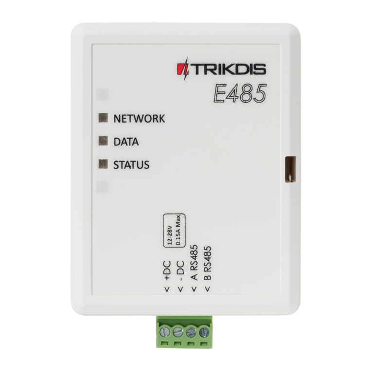
1.2 Wi-Fi module W485 elements
1. Indicator lights.
2. Frontal case opening slot.
3. Terminal for external connections.
1.3 Purpose of terminals
Terminal Description
+DC Power supply terminal (9-28 V DC positive terminal)
-DC Power supply terminal (9-28 V DC negative terminal)
A RS485 Terminal A of RS485 bus
B RS485 Terminal B of RS485 bus
1.4 LED indication of operation
Indicator Light status Description
NETWORK Green solid Connected to Wi-Fi network
Yellow blinking Shows signal strength from 0 to 10
DATA Green solid Message is being sent
Yellow solid Unable to send message
STATUS Green solid No operational problems
1 blink Unable to connect to Wi-Fi network
2 blinks Poor Wi-Fi signal strength

www.trikdis.com 6 May, 2019
Wi
-
Fi
module
W
485
Indicator Light status Description
3 blinks Not connected via at least one of the channels
If none of the LED indicators are active, check the power supply and connections.
2 Schematics for connecting the Wi-Fi module W485
3 Setting parameters
Connect the W485 module to a Wi-Fi network. To do
this, use a phone or a laptop. Open the Wi-Fi access to
the internet window. Choose the network W485_xxx.
In order to connect to the W485_xxx network, you
need to enter the password (default password -
12345678) and click CONNECT.
1. Open a browser and enter the IP address
192.168.12.1. In the window that opens, enter the
password (default password – 123456). Click
LOGIN.

www.trikdis.com 7 May, 2019
Wi
-
Fi
module
W
485
2. If the box Use DHCP is ticked in the Network
settings window, the Wi-Fi module will
automatically read the network parameters
(Gateway, Net mask, Static IP) and the module
will be assigned an IP address.
Set the necessary settings and click Save.
3. Choose a Wi-Fi network in the WIFI settings
window.
4. Enter the Wi-Fi network password.
6.Click the Join button.

www.trikdis.com 8 May, 2019
Wi
-
Fi
module
W
485
If the network is not on the Available network and
signal strengths list or if it is hidden, you must:
4. Enter the Wi-Fi network password.
5. Enter the network name in the Use custom SSID
field and tick the box.
6. Click the Join button.
7. A window will open. You must wait for the module
to connect and then click Back.
The connection will be configured and the Wi-Fi
module will be assigned an IP address.

www.trikdis.com 9 May, 2019
Wi
-
Fi
module
W
485
„General settings“ window
Account ID – enter device number.
Account ID from master – if the box is ticked,
messages will be sent with the number of the main
device (the one that the Wi-Fi module is connected
to).
Test period – period for sending TEST connectivity
check messages.
Time sync. – choose which server (receiver’s or
Protegus) to use for time synchronization.
Transparent - remove the check box to make the
module W485 work with T16 and SP231.
Internal events – settings for sending internal
events.
Set the necessary settings and click Save.

www.trikdis.com 10 May, 2019
Wi
-
Fi
module
W
485
“Reporting” window
General settings:
Backup reporting after – specify the number of
unsuccessful attempts to send a message using the
primary channel before switching to the backup
channel.
Return to primary after – specify the time period
after which the device will attempt to regain
connection via the primary channel.
Primary channel:
Mode – specify the protocol (TCP or UDP) for
sending messages.
Host – enter the receiver’s IP address.
Port – enter the receiver’s network port number.
Encryption key – enter the encryption key.
Ping interval – enter the time period in between
PING signals.
Backup channel:
Set the parameters for the backup channel. This will
ensure that if connectivity via the primary channel
is lost, events will be sent via the backup channel.
Configure the backup channel using the setting field
descriptions above.
Protegus:
Enable Protegus: - enable Protegus service the,
W485 will send notifications to Protegus app.
Set the necessary settings and click Save.
“Access settings” window
Login pass – set the password for connecting with
the Wi-Fi module.
Set the necessary settings and click Save.
4 Adding the Wi-Fi module W485 to Protegus app
Adding the Wi-Fi module W485, which is connected to the radio transmitter T16, to Protegus. With
Protegus the user will see the status of the system and receive event notifications.
1. Download and launch the Protegus application or use the browser version: www.protegus.eu/login

www.trikdis.com 11 May, 2019
Wi
-
Fi
module
W
485
2. Log in with your user name and password or register and create new account.
Important: When adding the W485 to Protegus check if:
1. Protegus cloud is enabled;
2. Power supply is connected (“POWER” LED illuminates green);
3. Registered to the Wi-Fi network (“NETWORK” LED illuminates green and blinks
yellow).
3. Click Add new system and enter the W485’s “MAC” address. This address can be found on the device
and the packaging sticker. Click Next.
4. In the new window, click Areas in the side menu. In the next window, specify how many alarm system
areas.
5. In the new window, identify what is the number for each of the specified areas in the security system
and press Save.

www.trikdis.com 12 May, 2019
Wi
-
Fi
module
W
485
Table of contents
Other Trikdis Control Unit manuals