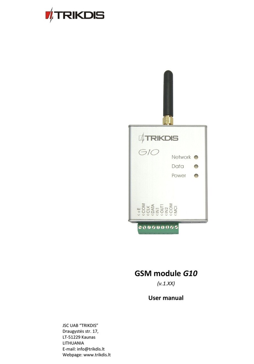
Trikdis G10T User manual

GSM module G10T
(v.2.3X)
Installation manual
TRIKDIS, JSC
Draugystės st. 17,
LT-51229 Kaunas
Lithuania
E-mai : info@trikdis. t
www.trikdis. t

2
Table of Contents
GSM modu e G10T ..................................................................................................................................................................... 3
Operating ................................................................................................................................................................................... 3
Outside view ............................................................................................................................................................................... 3
Modu e insta ation steps ........................................................................................................................................................... 4
Recommendations for programming of security contro pane .................................................................................................. 4
Wiring diagram ........................................................................................................................................................................... 5
Setting of operating parameters ................................................................................................................................................ 5
Updating modu e firmware version ............................................................................................................................................ 9
Setting of configuration remote y............................................................................................................................................... 9
Firmware version upgrading remote y ..................................................................................................................................... 10
Remote PGM output switching ................................................................................................................................................ 10
Technica specification.............................................................................................................................................................. 11
Package contents...................................................................................................................................................................... 11
Safety requirements ................................................................................................................................................................. 11
Liabi ity restrictions .................................................................................................................................................................. 11

3
GSM module G10T
Modu e G10T is designed for transmitting messages of security system to an a arm receiving centre (ARC) through a GSM
connection. Modu e features:
−Receives messages from te ephone ine communicator of security contro pane ;
−Can transmit messages to an ARC through GPRS connection or DTMF via GSM VOICE or with SMS messages;
−Every GPRS, SMS and GSM VOICE channe can be set to be primary and / or backup GSM communication with an ARC,
id est messages are sent through a primary GSM connection channe and if it fai s – through a backup GSM channe ;
−Even if GPRS connection is ost with two servers, information can be sent with SMS messages;
−Messages receivers: software IPcom; hardware (HW) receivers RL10 and RM10 and GM5; a most every te ephone
receiver;
−Domain can be set as an IP address of IP receiver;
−Sent messages correspond with Contact ID protoco codes;
−The modu e can send SMS messages to 4 user mobi e phones;
−Operating parameters and firmware version can be updated remote y;
−Operating parameters are set with the program G10config.
Operating
The modu e G10T is connected to security contro pane contacts for connecting a te ephone and ine. In case of an event,
the security contro pane dia s number 1234. Modu e G10T picks up the phone and receives contro pane message. After
receiving the message, the modu e transmits it to ARC through GSM connection channe set as primary. If the modu e is
unab e to transmit the message through the primary connection channe , the modu e can send it through GSM connection
channe set as backup. Messages are sent through GSM connection according to set IP addresses or te ephone numbers.
If the modu e oses connection with both the primary and the backup IP addresses, the modu e can send information to ARC
with SMS messages.
If G10T oses communication with both primary and backup IP receiver then it wi send Contact ID messages with encrypted
SMS to SMS receiver (modem) at ARC.
The modu e can send messages to specified recipients about the breakage/restoration of externa circuits IN1 and IN2.
Messages can be sent with SMS messages to four mobi e phones. SMS message can contain of user-friend y text which
describes security contro pane event.
Modu e output OUT1 state wi invert when GSM connection with server at ARC fai s/restores or when the modu e receives
an SMS message containing of command to change its output state.
Modu e can periodica y transmit signa s PING for testing communication channe .
Note: if G10T has not had communication with any receiver at ARC, it sends communication troubl signa to a arm contro
pane .
Outside iew
1. Termina b ock
2. SIM card ho der
3. USB socket
4. GSM antenna
5. LED “Network”
6. LED “Data”
7. LED “Power”
Description of terminal block
Contact
D scription
+E
+12V
power supp y c amp
COM
Common c amp
T
IP
For connecting to the TIP c amp of security contro pane
R
ING
For connecting to the RING c amp of security contro pane
IN1
1
st
input c amp
(NC t
ype
)
IN2
2
nd
input c amp (NC type
)
OUT1
PGM
output c amp
(
OC
t
ype
)
COM
Common c amp
MCI
Provided for future use

4
Light indication
LED Op ration D scription
Network presents
status of connection to
GSM network
Green ON Modu e has been connected to GSM network
Ye ow ON Message is being sent
Green f ashing Connecting to GSM network
Ye ow f ashing
Number of ye ow f ashes represent GSM signa
strength
Data presents data
exchange.
Green ON Unsent messages present in modu e memory
Red ON Unab e messages to be sent
Green f ashing Messages are being received from the contro pane
Red f ashing rapid y Modu e configuration is incorrect
Red f ashing SIM card error
Power presents power
supp y status,
functioning of
microcontro er and
programming status
Green f ashing
Power supp y is sufficient, microcontro er is
functioning
Ye ow f ashing Power supp y is not sufficient (
≤11,5 V) but
microcontro er is functioning
Green and ye ow f ashing in turn Programming mode
Module installation steps
St ps Not s
1. Set the operating parameters for the security
contro pane te ephone communicator according
to the se ected mode of connection with ARC.
Fo ow recommendations in chapter Recommendations for
programming of security control panel.
2. Set the operating parameters for the modu e
G10T.
Fo ow information in chapter Setting of operating
parameters.
3. Put SIM card activated in GSM/GPRS network in.
Contact a GSM service provider regarding a SIM card. We do
not recommend using pay as you go (prepaid) SIM cards.
4. Fasten the modu e to the security contro pane
meta casing by using either M3x6 screws or
adhesive fastening tape.
The ocation and dimensions of ho es to be dri ed in the
casing for fastening the modu e and antenna:
5. Screw the GSM antenna on.
6. Connect the modu e to the security contro pane
according to wiring diagram given be ow.
See chapter Wiring diagram.
7. Turn on the system power supp y.
8. Check GSM signa strength according to ight
indication.
Sufficient GSM signa strength is eve 5 (five ye ow f ashes of
indicator Network). If GSM signa strength is not sufficient,
use other antenna type.
9. Check if the modu e sends messages according to
its configuration
The message must be sent and received at the specified IP
address. If messages are sent to a mobi e phone, check if a
SMS messages are received.
Recommendations for programming of security control panel
Use Programming manua of particu ar security contro pane and set operation parameters of te ephone communicator as
fo owing:
1. Enter the te ephone numbers to which the security contro pane wi dia in case of an event. Te ephone number of
G10T is 1234. Set that this number wou d be dia ed with DTMF tones. When contro pane rings by this number, G10T
picks up the phone wi be ready to receive security contro pane ’s Contact ID report.
2. Set that in case of an event, the security contro pane wou d dia messages in Contact ID format with DTMF tones.

5
Wiring diagram
Setting of operating parameters
Modu e G10T operating parameters are set with computer program G10config. The program can be found in website
www.trikdis. t.
1. Connect the modu e G10T with a computer using a USB cab e.
Note: USB drivers must be insta ed in the computer. If the modu e is connected to a computer for the first time, MS
Windows OS shou d open a Found New Hardware Wizard window for insta ing USB drivers. Down oad the USB
driver fi e USB_COM.inf for MS Windows OS from the website www.trikdis. t. In the wizard window se ect the
function Yes, this time only and press the button Ne t. When a new window Please choose your search and
installation option” wi open, press the button Browse and se ect the p ace where the fi e USB_COM.inf was saved.
Fo ow the remaining wizard instructions to finish the USB driver insta ation.
2. Start the program G10config.
3. Se ect the program directory Settings.
In the drop-down ist Port se ect the port to which the
modu e is connected.
Note: specific port to which the device is connected wi
appear on y when the device is proper y connected.
In the drop-down ist Language se ect the desired program
anguage.
1. Press the button Connect/Disconnect [F2/F8].
When the modu e G10T is connected to a computer, modu e
LED Power indicator shou d f ash green and ye ow in turn.
Program G10config status bar shou d indicate connection
status Connected and disp ay the fo owing information
about the connected modu e:
Modu e type
Modu e seria number
Firmware version insta ed in the modu e
4. Press the button Read [F7].
When the window Access code opens, enter th access code
(defau t access code is 1234) and press the button OK.
If you want for the program to remember your access code,
check the box Remember. Then the Access code window wi
not open when connecting to the modu e for the next time.

6
Se ect the program directory Main and set the fo owing parameters:
Object ID G10T transfers messages of security contro pane containing its ID number set in. Here is
the section for setting ID number (0001-FFFF) for G10T in case to identify to which object
be ong messages generated by particu ar G10T. Set 4 symbo va ue;
SIM Card PIN code Section for entering the SIM card PIN code. Leave this fie d by defau t if PIN code request is
disab ed;
User code Section for entering a user code. When connected using a User code, on y those modu e
parameters can be changed, which change were a owed by the administrator;
Admin code Section for entering an administrator code. When connected using an Admin code, a
modu e parameters can be changed and a so access to parameter change can be restricted
for persons connecting with the User code.
Panel type Option INTERFACE DTMF means that the modu e is app ied to receive information coded in
Contact ID format from the te ephone communicator of the security contro pane in DTMF
codes;
IN1 If here were se ected the option 24 zone in the drop-down ist then after braking of input
IN1 externa circuit, the modu e wi transmit a message about this event with a code set in
the tab e Module events.
If here were se ected the option Backup mode then modu e G10T wi start transmitting
messages of security contro pane after breaking input IN1 externa circuit on y;
PGM If the option Remote control SMS is se ected in the drop-down ist, the modu e wi change
its output state after receiving an SMS message containing a contro command (See chapter
Remote output state control). If the option Lost Primary channel is se ected, output state
wi change to the opposite after osing communication through the primary channe . When
the option Lost Secondary channel is se ected, output state wi change to the opposite
after osing communication through the backup channe . If the option Lost Both channels is
se ected, output state wi change to the opposite after osing communication through the
primary and backup channe s;
GPRS PING time Time interva according to which the modu e wi send signa s PING for po ing GPRS
connection;
CSD PING time The function is disab ed;
SMS PING time Time interva according to which the modu e wi send signa s PING for po ing SMS
communication;
Test time Time interva according to which the modu e wi send messages T st.

7
The directory GPRS. Enter the parameters are needed for reporting to an a arm receiving centre (ARC):
Primary reporting Se ect the primary communication channe in the ist, through which the modu e wi transmit
messages to ARC.
If GPRS is se ected, enter the IP address or domain name and the port number of ARC in the
corresponding boxes Server IP1 address or Domain and Port;
If DATA is se ected, enter the te ephone number of ARC Tel.1, to which messages wi be sent
through GSM connection in DTMF tones. The te ephone number shou d be entered with
internationa country code but without the “+” (p us) sign.
If SMS is se ected, enter the te ephone number of ARC Tel.1, to which SMS messages wi be
sent. The te ephone number shou d be entered with internationa country code but without
the “+” (p us) sign.
Backup reporting Drop-down ist for setting the backup communication channe , through which the modu e wi
transmit messages, when connection through the primary communication channe is ost.
If GPRS is se ected, enter the second server IP address or domain name and the port number
of ARC server to the corresponding boxes Server IP2 address or Domain and Port.
If DATA or SMS is se ected, enter the te ephone number of ARC Tel.2, to which messages wi
be sent through GSM connection in DTMF tones or SMS messages. The te ephone number
shou d be entered with internationa country code but without the “+” (p us) sign.
Second backup reporting tel Te ephone number of ARC’s receiver, to which SMS messages wi be sent, when the modu e
has ost GPRS connection with both servers. This option is a owed, when both the primary
and the backup GSM connection channe s are se ected as GPRS. The te ephone number
shou d be entered with internationa country code but without the “+” (p us) sign.
Protocol Drop-down ist for se ecting a protoco for encrypting messages;
Encryption key Section for entering a 6-digit key for encrypting messages sent to ARC. The password must be
same as the password entered in a server program IPcom.
Return to primary after Used if both the primary and backup GSM channe s are se ected for connection with ARC.
Enter in the section the duration of time for sending messages though the backup
communication channe , when connection through the primary channe has fai ed;
Backup reporting after Used if both the primary and backup GSM channe s are se ected for connection with ARC.
Enter in the section the number of attempts to transmit information through the primary
communication channe , after which the modu e wi connect to the backup communication
channe .
Note: Administrator of an a arm receiving centre (ARC) shou d provide the IP addresses, port and te ephone numbers,
encryption protoco , key and other parameters necessary for connecting with ARC.
APN Access point name for connecting to the GSM operator’s network;
User User name for connecting to the GSM network;
Password Password for connecting to the GSM network;
DNS1, DNS2 We recommend eave va ues by the defau t in the sections if you don’t get other.
Note: APN, user name and password shou d be provided by the GSM network administrator, from which you have received
the SIM card.
Module events Modu e events are described in the tab e. After their occurring the modu e transmits
messages with codes given beside. Event code can be changed by doub e-c icking the ce s
Contact ID event code or Contact ID restore code and by entering exact va ues by Contact ID
form in the new y opened window. After entering the va ues press the button OK.

8
Modul v nts Meaning of event “E“ Meaning of event “R“
TIME Interna c ock of the modu e is not set Interna c ock of the modu e is set
TEST Periodica modu e T st message
POWER Power supp y vo tage is ower than 11,5 V Power supp y vo tage has restored to 12,6 V
TAMPER_1 Externa circuit of Input IN1 has broken Externa circuit of Input IN1 has restored
TAMPER_2 Externa circuit of Input IN2 has broken Externa circuit of Input IN2 has restored
If you need to send SMS messages to user of security system, choose the directory Te t SMS reporting and enter the
parameters for SMS messages to be sent:
Telephone Te ephone numbers T1, T2, T3, T4 of the four users to which SMS messages wi be sent. The
te ephone numbers shou d be entered with internationa country code but without the “+”
(p us) sign;
Name Choose by which te . number G10T must send SMS after occurring event of particu ar type.
Alarm/Restore Messages wi be sent when the security system is a armed/restored (events with E/R 1XX
codes);
Open/Close Messages wi be sent about the arming/disarming of the security system (events with E/R
4XX codes);
Troubles Messages wi be sent about the troub es(restores) in system operation (events with E/R 3XX
codes);
Tests System test messages wi be sent (events with E 6XX codes).
SMS encoding Choose in the ist drop-down the preferred encoding for the text in SMS messages;
Send SMS When All is chosen, a messages received from the security contro pane wi be sent to
users. When Described Only is chosen, SMS messages wi be sent on y about the events in
described zones;
Object ID Enter the object name. It wi be inc uded in the message sent to user;
Users Entries in the tab e are associated with user codes, with which the security system is
armed/disarmed. When a user arms/disarms the security system with his code, his name
entered in the tab e wi be inc uded in the SMS message;
Zones Entries in the tab e are associated with events in protected zones. When zone is
a armed/restored, its name entered in the tab e wi be inc uded in the SMS message;
Partitions If the security system is divided into severa individua y protected areas, entries in the tab e
are associated with these areas. If a zone is a armed/restored in an area, the name of the
partition entered in the tab e wi be inc uded in the SMS message;

9
5. Press the button Write [F6] and va ues entered in the program G10config windows wi be up oaded to the modu e
G10T.
6. Press the button Disconnect [F8] and unp ug the USB cab e from the USB socket.
Save [F5] By pressing this button va ues entered to the program G10config can be saved in the
computer. A new fi e with extension .gst wi be created. It can be used ater as a temp ate for
configuring other modu es.
Restore [F11] Button for restoring defau t (factory) operating parameters of the modu e G10T. Press the
button Yes when request window opens.
Updating module firmware ersion
When the manufacturer adds new features to the modu e G10T, firmware of the previous y bought modu e can be updated:
1. Down oad the atest G10T_vx.xxx.prg update fi e from the website www.trikdis. t.
2. Connect the modu e G10T to a computer and start the program G10config. Open directory Firmware update and se ect
the fi e G10T_v2.xxx.prg saved in the computer.
3. Press the button Start [F9]. Wait unti fi e up oading bar Progress is fu , then press the button Disconnect [F8]. Unp ug
the USB cab e.
4. P ug the USB cab e back in. Firmware update process may take 60-90 seconds. Wait unti indicator Data wi stop
f ashing green and press the buttons Connect [F2] and Read [F7]. The new version of the modu e firmware wi be
disp ayed in G10config program status bar.
Setting of configuration remotely
In order to set modu e G10T operating parameters remote y a SMS message with the particu ar syntax must be sent by GSM
number of SIM card put in the modu e G10T. When the modu e G10T receives this SMS message it opens GPRS
communication session with software IPcom.
If during the previous setting modu e operating parameters were being entered
GSM number of authorised person in the ist G10config / S ttings / Wir l ss
programming phon s, the modu e G10T wi open GPRS communication session, if it
receives SMS message with particu ar syntax from authorized person‘s phone.
SMS message text structure (word
space
means space between SMS text symbo s):
CONNECT
space
1234
space
SERVER=100.100.100.100
space
PORT=1000
space
APN=provider
space
USR=name
space
PSW=psw
space
ENCR=enc
Note: entering va ues use capita etters!
Description of syntax:
CONNECT Enter the word “CONNECT” means starting command;
9874 Enter your 4-digit access code to modu e parameter configuration (defau t is
1234);
SERVER=va ue Enter the word “SERVER=” + enter IP address of the IP receiver, from which
modu e operating parameters wi be configured;
PORT=va ue Enter the word “PORT=” + enter port of the receiver, from which modu e
operating parameters wi be configured;
APN=va ue
Enter the word “APN=” + enter the GPRS access point name of network where
SIM card is operating. If GSM service provider doesn’t require any va ue must
be entered, just eave ...
space
APN=
space
... in SMS;
USR=va ue
Enter the word USR= + enter the Us r nam of GPRS access point name of
network where SIM card is operating. If GSM service provider doesn’t require
any va ue must be entered, just eave ...
space
USR=
space
... in SMS;
PSW=va ue
Enter the word “PSW=” + enter the Password of GPRS access point name of
network where SIM card is operating. If GSM service provider doesn’t require
any va ue must be entered, just eave ...
space
PSW=
space
... in SMS;
ENCR=va ue Enter the word “ENCR=” + enter the 6-digit messages decrypting key which is
set in IP receiver (defau t is 123456).

10
Order of actions after the message is sent:
1. Open the window of software IPcom and se ect the object ID, which operating parameters of transmitting modu e
shou d be changed. To se ect, right c ick on the ID number.
2. Open the configuration program G10config. Left c ick on the icon G10config has been appeared beside the se ected
ID number.
3. C ick on the button Connect in the opened program G10config too bar. GPRS connection status “Conn ct d” must
be indicated in the program’s status bar. C ick the button Read [F7] on, o d configuration to be disp ayed.
4. Further actions are identica as when the modu e is connected to a computer with a USB cab e. Just set the
desirab e va ues of modu e operating parameters in the opened program G10config windows.
5. After entering desirab e va ues c ick the button Write [F6] on, the va ues to be set in the modu e G10T. Just c ose
the program G10config and GPRS communication session c oses too.
Firmware ersion upgrading remotely
Connect the modu e G10T with the program G10config remote y (See previous chapter how to connect remote y).
1. Open the program G10config (See previous chapter how to open the configuration program)
2. Press the button Connect.
3. To read the parameters set in the modu e press the button Read.
4. Open the window Firmware and with c icking on the button Browse se ect the atest version of the firmware fi e.
Press the button Start.
5. Wait unti the firmware wi be written into the modu e processor memory. This may take 1-3 minutes, after which
the modu e wi reconnect to the program G10config.
6. Set the modu e operating parameters in the same way as described whi e connected via USB port.
Remote PGM output switching
In order to change the state of output OUT1, send an SMS message to the SIM card number of the modu e. Examp es of SMS
messages are provided in the tab e be ow.
Notes:
−If the ist Wireless programming phones is empty, modu e wi change its output state after receiving an SMS message
from any mobi e phone. If te ephone numbers are entered in the ist, modu e output state can be changed on y from
these phones;
−Output state can be changed when output OUT1 operating mode is set to Remote control SMS;
−SMS messages have to be written in capita etters on y!
SMS m ssag t xt M aning Not
OUTPUT˽1234˽ON Output state is changed to ON Instead of numbers 1234 enter your
Administrator or Us r code
Key “˽“ means space tab. Spaces in
notified p aces must be entered.
OUTPUT˽1234˽OFF Output state is changed to OFF
OUTPUT˽1234˽PULSE=005 Output state is changed to ON for
time period given in seconds
RESET˽1234 Restart modu e

11
Technical specification
Power supp y vo tage DC 12,6 ± 3 V
Used current 60–100 mA (stand-by),
Up to 250 mA (transmitting)
GSM modem frequency 850 / 900 / 1800 MHz
Memory Up to 60 messages
Inputs 2, NC type
Output 1 OC type, commutating up to 30 V vo tage and current up to 1 A
Setting configuration Through the USB port
Operating environment From -10 °C to 50 °C, with re ative air humidity 80% when +20 °C
Dimensions 65 x 79 x 25 mm
Package contents
Modu e G10T 1 pc.
Two-sided adhesive tape (10 cm) 1 pc.
Note:
GSM antenna of desired type is co ected by the additiona request.
Safety requirements
P ease read this manua carefu y before using the security modu e G10T.
Security modu e G10T shou d be insta ed and maintained by qua ified personne , having specific know edge regarding the
functioning of GSM devices and safety requirements.
Modu e G10T shou d be mounted in p aces with restricted access and in safe distance from any sensitive e ectronic
equipment. The device is not resistant to mechanica effects, dampness and hazardous chemica environment.
Liability restrictions
−When buying the Device, the Buyer agrees that the Device is a part of a security system of premises, which sends
messages about security system status. The Device, when insta ed, does not diminish the probabi ity of burg ary, fire,
intrusion or other breach of premises.
−UAB “TRIKDIS” is not responsib e for burg ary, fire or any other breach of Buyer’s and/or User’s premises and is not
iab e for any direct or indirect damages incurred thereof.
−When buying the Device, the Buyer agrees that the Device supp ied by UAB “TRIKDIS” fu y meets his requirements for
intended use.
−UAB “TRIKIDIS” provides no guarantees that the Device sha function as dec ared if the Device is insta ed and used not
according to its origina purpose, user manua and re evant e ectronic and technica conditions.
−UAB “TRIKDIS” is in no way associated with GSM/GPRS/Internet service providers (operators), thus UAB “TRIKDIS” is in
no way responsib e for any defects in Device operation if they have occurred because of the oss of GSM/GPRS/Internet
connection, or because of other defects in the service provider network.
−UAB “TRIKDIS” has no contro and is not responsib e for the prices and marketing of network services provided by the
GSM/GPRS/Internet service providers.
−UAB „TRIKDIS” is not responsib e if GSM/GPRS/Internet services are not provided to the Buyer and/or User of the
Device or were cance ed and any direct or indirect damages were incurred thereof.
−UAB „TRIKDIS” is not responsib e for any direct or indirect damages incurred by the Buyer and/or User of the Device
due to oss of e ectricity.
−UAB „TRIKDIS” is not iab e if Device firmware versions were not updated by the Buyer and/or the User on time.
−User manua of the Device can contain technica inaccuracies, grammatica or typographica errors. UAB “TRIKDIS”
reserves the right to correct, update and/or change information in the insta ation manua .
Other manuals for G10T
1
Table of contents
Other Trikdis Control Unit manuals
