Trikdis E10 User manual

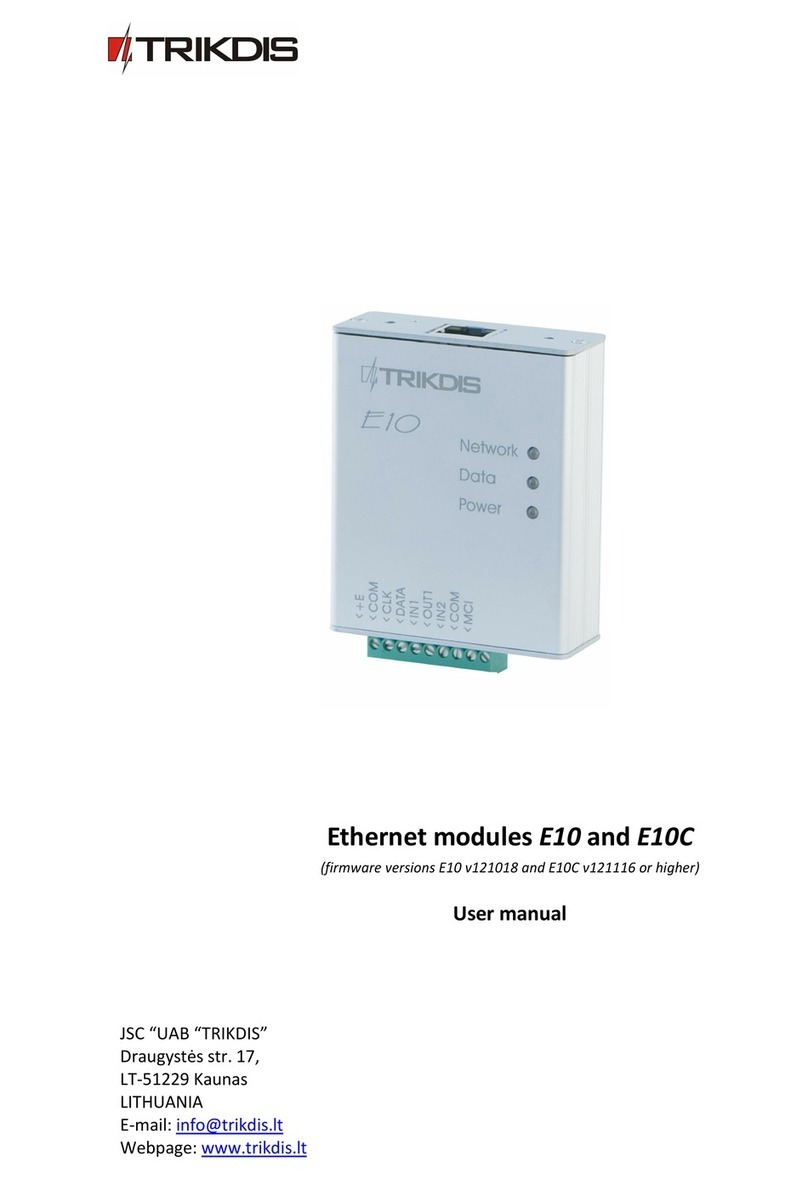
Ethernet module E10
(v.YYMMDD)
User manual
JSC “UAB “TRIKDIS”
Draugystės str. 17,
LT-51229 Kaunas
LITHUANIA
E-mail: info@trikdis.lt
Webpage: www.trikdis.lt

- 2 -
Table of contents
Ethernet module E10.................................................................................................................................................3
Description of device operation ................................................................................................................................3
Module overview.......................................................................................................................................................3
Module installation....................................................................................................................................................4
Setting of operating parameters................................................................................................................................5
Updating module firmware version...........................................................................................................................7
Setting of operating parameters remotely ................................................................................................................7
Technical parameters ................................................................................................................................................8
Package content ........................................................................................................................................................8
Safety requirements
Please read this manual carefully before using the security module E10.
Security module E10 should be installed and maintained by qualified personnel, having specific knowledge regarding the
functioning of GSM devices and safety requirements. The device must be disconnected from external power supply source
before starting device installation.
Module E10 should be mounted in places with restricted access and in safe distance from any sensitive electronic
equipment. The device is not resistant to mechanical effects, dampness and hazardous chemical environment.
Liability restrictions
-When buying the Device, the Buyer agrees that the Device is a part of a security system of premises, which sends
messages about security system status. The Device, when installed, does not diminish the probability of burglary, fire,
intrusion or other breach of premises.
-UAB “TRIKDIS” is not responsible for burglary, fire or any other breach of Buyer’s and/or User’s premises and is not
liable for any direct or indirect damages incurred thereof.
-When buying the Device, the Buyer agrees that the Device supplied by UAB “TRIKDIS” fully meets his requirements for
intended use.
-UAB “TRIKIDIS” provides no guarantees that the Device shall function as declared if the Device is installed and used not
according to its original purpose, user manual and relevant electronic and technical conditions.
-UAB “TRIKDIS” is in no way associated with GSM/GPRS/Internet service providers (operators), thus UAB “TRIKDIS” is in
no way responsible for any defects in Device operation if they have occurred because of the loss of GSM/GPRS/Internet
connection, or because of other defects in the service provider network.
-UAB “TRIKDIS” has no control and is not responsible for the prices and marketing of network services provided by the
GSM/GPRS/Internet service providers.
-UAB „TRIKDIS” is not responsible if GSM/GPRS/Internet services are not provided to the Buyer and/or User of the
Device or were cancelled and any direct or indirect damages were incurred thereof.
-UAB „TRIKDIS” is not responsible for any direct or indirect damages incurred by the Buyer and/or User of the Device
due to loss of electricity.
-UAB „TRIKDIS” is not liable if Device firmware versions were not updated by the Buyer and/or the User on time.
-User manual of the Device can contain technical inaccuracies, grammatical or typographical errors. UAB “TRIKDIS”
reserves the right to correct, update and/or change information in the installation manual.

- 3 -
Ethernet module E10
Ethernet module E10 is designed to transmit messages from security control panel at a secured object to a monitoring
station through Internet connection. The module features:
-Messages are transmitted to one a IP address of monitoring station by TCP/IP or UDP/IP protocol;
-In case of communication failure with the main IP address, it transmit messages to a backup IP address;
-Data transmission contains information in Contact ID codes;
-Setting of operating parameters is implemented with a program Econfig while connected via USB or Internet
connection.
Description of device operation
When connected to a DSC, Caddx, Paradox or Pyronix security control panel data bus, the module receives its messages and
transmits them to a specified IP address of the monitoring station. If a message fails to be transmitted to this IP address, the
module E10 sends it to backup IP address.
The module can transmit messages if external circuits of inputs IN1 and IN2 are broken/restored.
The module can periodically send PING signals to monitor Internet connection.
Module output OUT1 state will change if Internet connection with the monitoring station has failed/restores.
Module overview
1. Holes to fasten the module (2 x M3)
2. Network socket RJ45
3. Switch “Reset“
4. Indicator “Network”
5. Indicator “Data“
6. Indicator “Power”
7. USB socket
8. Terminal block
Terminal block description
Contact
Purpose
+E
+12V power supply clamp
COM
Common clamp
CLK
Synchronizing signal clamp
DATA
Data signal clamp
IN1
1st input clamp (NC type)
OUT1
Output clamp (OC type)
IN2
2nd output clamp (NC type)
COM
Common clamp
MCI
Provided for future use
Light indication
LED
Operation
Description
“Network”displays connection to
the Internet status
Green ON
Module is connected to the Internet
Yellow ON
TCP/IP session is open
“Data”displays data transfer
Green ON
Unsent messages present
Red ON
Messages are unable to be sent
Green flashing
Messages are being received from the control panel
“Power”displays power supply
status and the functioning of the
microprocessor
Green flashing
Power supply is sufficient,
Yellow flashing
Power supply is not sufficient (≤11,5 V),

- 4 -
Module installation
Actions
Notes
1. Set module operating parameters.
Follow information in chapter Setting operating
parameters.
2. Fasten the module to the control panel metal
casing by using M3x6 screws or an adhesive
fastening tape.
The location and dimensions of holes to be drilled in
the casing for fastening the module:
3. Connect the module with other security system
devices according to the schemes given below.
See chapter Wiring diagrams.
4. Connect LAN cable.
Connected network must not restrict module
operation.
5. Turn on the system power supply.
6. Evaluate according to light indication if the
module has connected to the network.
Indicator Network must shine green.
7. Check if the module sends messages according to
its configuration.
The message must be received at the specified IP
address.
Wiring diagrams
Wiring diagram to DSC Power Series control panels:
PC1616, PC1832, PC1864 PC585, PC1565, PC5020.
Wiring diagram to Paradox control panels:
SPECTRA SP5500, SP6000, SP7000, 1727, 1728, 1738,
MAGELLAN MG5000, MG5050,
DIGIPLEX EVO48, EVO192, EVO96, NE96,
ESPRIT E55, 728ULT, 738ULT.
Wiring diagram to Pyronix Matrix Series control panels:
MATRIX 424, MATRIX 832, MATRIX 832+, MATRIX 6,
MATRIX 816.
Wiring diagram to Caddx control panels:
NX-4, NX-6, NX-8.

- 5 -
Setting of operating parameters
Module E10 operating parameters can be set with a computer program Econfig. The program is available in website
www.trikdis.lt.
1. Connect the module E10 with a computer USB port using a USB cable. Computer must have got the USB driver installed.
USB driver installation: If the module is connected to a computer for the first time, MS Windows OS should open the
window Found New Hardware Wizard for installing USB drivers. Download the USB driver file USB_COM.inf for MS
Windows OS from the website www.trikdis.lt. In the wizard window select the function Yes, this time only and press
the button Next. When the window Please choose your search and installation options opens, press the button
Browse and select the place where the file USB_COM.inf was saved. Follow the remaining wizard instructions to finish
the USB driver installation.
2. Start the program Econfig;
3. Choose the command Settings in the menu bar and select
the port to which the module is connected in the Serial port
list. Press the button OK.
Note: specific port appears only when the module is connected.
4. Choose the command Devices in the menu bar and select E10;
5. Press the button Read [F7] for the operating parameters set in the module to be read. If Access code request window
opens, enter your personal access code and click its button OK. Set parameters will be displayed in configuration
program’s windows and information about the connected module should be displayed in its status bar.
6. Choose the directory System Settings and set the following parameters:
Admin code
Section for entering an administrator code. When connected using an Administrator code, all
module parameters can be changed and access to parameter change for persons connecting with
the User code can be restricted.
User Code
Section for entering a user code. When connected using a User code, only those module
parameters can be changed, which change ware allowed by the administrator;
Allow user to see and
edit fields
If administrator marked particular fields person who connects using User code will see allowed
information;
Account Number
Section for entering a 4-digit module identification code;
Use internal account
Select this checkbox if messages from the security control panel must contain its identification
number;
Panel Type
Select the security control panel type, which is connected to the module E10. If interface C11, C14
or CZ6 is connected to the module, select the INTERFACE C11, C14, CZ6;

- 6 -
Test time
Periodic test messages will be sent according to a time interval set in this section;
Input
After external circuits of inputs IN1 and IN2 are broken, a message will be sent with an Alarm
Code, and when the circuits are restored –with a Restore Code;
Aand R
By selecting these checkboxes it can be chosen if messages about braking external circuits of
inputs IN1 and IN2 (A) and their restoring (R) should be sent.
Type
Section for selecting the desirable type of external circuits of inputs IN1 and IN2;
Output
Output OUT1 state will change to the opposite if the module will lose its Internet connection with
the server. If in the list PGM Mode is selected to Pulse, the output state will change for the
duration specified in the section Pulse time.
7. Choose the directory Ethernet TCP/IP options and set the following parameters for module connecting with the
monitoring station:
Internal MAC Address
A unique module physical address. It can be changed by selecting the checkbox Use Custom MAC
and entering desired values to the appropriate fields;
DHCP
When this checkbox is selected, module registration in the network will be done automatically. If
automatic registration is unsuccessful, enter Internal IP address, Gateway IP 2 address and subnet
Mask manually. E10 supports DNS service;
Primary Port
Section for entering the port number of IP receiver at monitoring station. If a backup IP receiver
exists, enter its port number in the section Backup Port.
Primary IP
Section for entering the IP address of the monitoring station. If a backup IP address exists, enter its
value in the section Backup IP.
Transport Protocol
List for setting transport protocol TCP/IP or UDP/IP for messages to be transmitted;
Time Return to
Primary IP
This section is used when both primary and backup IP addresses are set. The duration of time
should be entered for how long the module will send messages to the backup IP address when
primary communication is failed;
PING time
The module sends periodic PING signals Internet connection to be managed. Jus enter desirable
time period and mark the checkbox PING enable. We recommend enter value 60-180;
TCP data protocol
List for setting an encryption protocol for messages to be sent to the monitoring station. We
recommend to use the protocol TRK 03;
Password
Section for entering an encryption password for messages sent to the monitoring station. This
password must be identical to the decryption password entered in server program!
IP address, port number, network protocol, message encryption protocol and password and other parameters should be
provided by the administrator of the monitoring station.

- 7 -
In the directory Module Events a list of events is given, upon which happening the module will send messages with codes in
Contact ID format to the monitoring station:
Event
CID code
Description
Message transfer failed
1350FF000
Message transfer error, network problems
Periodical test
1602FF000
Periodic module Test message
Module reset
1308FF000
Module operation has been restarted
Low Battery
1302FF000
Module power supply voltage is lower than 11,5 V
Battery Restore
3302FF000
Module power supply voltage has returned to 12,6 V
8. Press the button Write and values were entered in fields of program Econfig will be transferred to the module E10.
9. The transmitting device is ready to operate. Unplug the USB cable from the USB socket.
Values were entered in Econfig windows can be saved in computer by pressing the button Save. A file with an
extension .tcfg will be created. It can be used later as a template to configure other modules.
Updating module firmware version
When the manufacturer adds new features to the module E10, firmware of the previously bought module can be updated:
1. Download the latest Econfig_xxx. file from the website www.trikdis.lt and install it in a computer.
2. Connect the module E10 to the computer with USB cable. Start the program Econfig and select the folder Firmware
and press the button Browse. In a newly opened window select the file E10.enc and press the button Open.
3. Press the button Start FW Update. Updating process starts by pushing micro switch Reset on the module. After
process finishing push the micro switch Reset one more time on.
4. Press the button Read [F7]. New firmware version will be displayed in the status bar of the program Econfig. Newly
configure the module.
5. Unplug the USB cable.
Note: When module firmware version is updated, module parameters will change to default (factory) settings. Module
parameters must be set again according to the instructions given in the chapter Setting of operating parameters.
Setting of operating parameters remotely
To implement setting of configuration in remote way is possible with program Econfig which is opened in environment of
soft IPcom.
1. Open window of soft IPcom. Select ID number [Object ID] of the module which will be configured and right-mouse click
it on.
2. Click start button of program Econfig which is appear beside the object ID.
3. After opening program Econfig window click the button Read on. If Internet connection with the module is, the
program Econfig will display the state Connected of this connection in its status bar.
4. Operation parameters of the module E10 are configured in the same way as the module is connected with USB cable
(see Setting of operating parameters).
5. If you choose the folder Firmware of the program Econfig you’ll be able to upgrade the module with new firmware
version. Just click the button Browse on. Select the file E10_Remote.enc and click the button Open. Then click the
button Start FW Update on. After completing the Updating process click the button Read [F7]. The firmware version of
the module will be displayed in status bar of program Econfig. Newly configure the module.
6. After entering desirable operating parameters into boxes of program Econfig click the button Write for storing
configuration in memory of the module. After closing the program Econfig, Internet connection session will be
cancelled too.

- 8 -
Technical parameters
Power supply voltage
DC 12,6 ± 3 V
Current consumption
120 mA (stand-by)
Up to 250 mA (transmitting)
Ethernet connection
IEEE802.3, 10 Base-T, RJ45 socket
Data pack content
Contact ID format codes
Memory
Up to 100 messages
Inputs
2, NC/NO/EOL-2,2 kΩ type
Output
1 OC type, commutating voltage up to 30 V and current up to 1 A
Configuration
Through the USB port with program Econfig
Operating environment
From -10 °C to 50 °C, with relative air humidity 80% when +20 °C
Dimensions
65 x 79 x 25 mm
Package content
Module E10
1 pc.
User manual
1 pc.
Two-sided adhesive tape (10 cm)
1 pc.
Fastening bolts M3 x 6
2 pcs.
Other manuals for E10
1
Table of contents
Other Trikdis Control Unit manuals
