Cooper Scantronic 8844 User manual

Installation Guide
8844
GPRS Module

2
Contents
Introduction ..................................................................3
Overview ....................................................................3
Installation....................................................................3
Preparation .................................................................3
Choosing a network account........................................3
Siting the antenna .....................................................3
Checking network signal strength ................................4
Dealing with poor signal strength.................................5
Preparing the 8844 ......................................................5
Fitting to a 7510r.........................................................6
Fitting to an i–on40.................................................... 10
Programming............................................................... 12
Programming Overview............................................... 12
Checking that the Module Works .................................. 13
Registering Your SIM Card........................................... 13
O2......................................................................... 14
T-Mobile................................................................. 14
Orange................................................................... 14
Vodafone................................................................ 15
Top Up Cards ............................................................ 15
Set Up GPRS Hostname, Username, and Password ......... 15
Set Up the IP Address of the ARC................................. 16
Setting up for Downloader........................................... 17
© Cooper Security Ltd. 2009
Every effort has been made to ensure that the contents of this book are correct. However, neither the
authors nor Cooper Security Limited accept any liability for loss or damage caused or alleged to be caused
directly or indirectly by this book. The contents of this book are subject to change without notice.
Printed and published in the U.K.

8844
3
Introduction
Overview
The 8844 is a plug-in module that allows the 7510r and
i-on40 control units to communicate with both fixed and
mobile destinations over the mobile phone network. In
addition the 8844 allows the control unit to communicate with
remote monitoring equipment using TCP/IP protocol.
The module must be fitted within the body of the control unit,
which has sockets for that purpose. This manual provides
brief instructions on fitting the 8844 within the 7510r and the
i–on40.
1
2
1. Antenna input socket. 2. SIM card holder.
Figure 1. 8844 PCB
Installation
Preparation
Before installing the 8844, please consider the type of
network account and the physical location of the unit and its
antenna.
Choosing a network account
Avoid using a pay as you go account. If you must, then be
aware that the 8844 cannot warn you of low credit. Set up
regular top-ups for the account or manage it through the
internet (if the provider gives you that option).
Siting the antenna
Before installing the unit you must decide on a suitable
location for the antenna. Site the antenna so that it can

8844
4
receive a good signal from the phone network. Note that the
supplied antenna lead is 3m long.
Place the antenna:
As high as possible.
As far away from the control unit as possible.
At least 1 metre from any metalwork (pipes, cabinets,
cabling, cement reinforcing bars, metallic coated glass).
Vertically (see Figure 2).
So that the lead runs horizontally from the antenna for at
least 250mm.
250mm
2,000 mm
No metal within
this area.
2,000 mm
Figure 2. Aerial Positioning
Checking network signal strength
There are three ways to check the network signal strength at
your installation:
1. You can use your mobile phone, provided that it is
registered with the same network as the SIM (Subscriber
Identity Module) card that you intend to fit to the 8844. If
your phone reports at least two bars of signal at the site of
the 8844 antenna then the 8844 should be able to work on
that network.
NOTE: When testing the signal strength you must hold your
phone in the exact location of the 8844 antenna.
If you decide that a location has a good signal, then you must
fit the centre rib of the 8844 antenna within 20mm of the
spot occupied by your phone. (The signal wavelength is so
short, that moving 80mm can change the signal strength

8844
5
markedly. This may not matter with a strong signal, but with
a weak signal it could mean that the 8844 will not register.)
2. If your phone does not work on the same network as the
SIM you intend to install in the 8844, then, provided your
phone is not locked, you can put the 8844 SIM in your phone,
and test for network signal strength as described in step 1.
Ensure that you can make a call from the chosen position, it
is not enough to rely on the signal strength indication.
Once you have completed testing you must remember to shut
down your phone in the recommended manner before
extracting the 8844 SIM. If you remove power abruptly (for
example by taking the phone battery out) the SIM card may
not have time to de-register from the network, and some
networks may lock out the SIM for several hours.
Note: Do not lock the SIM card with a PIN (the 8844 will not
let you key in a PIN for the card).
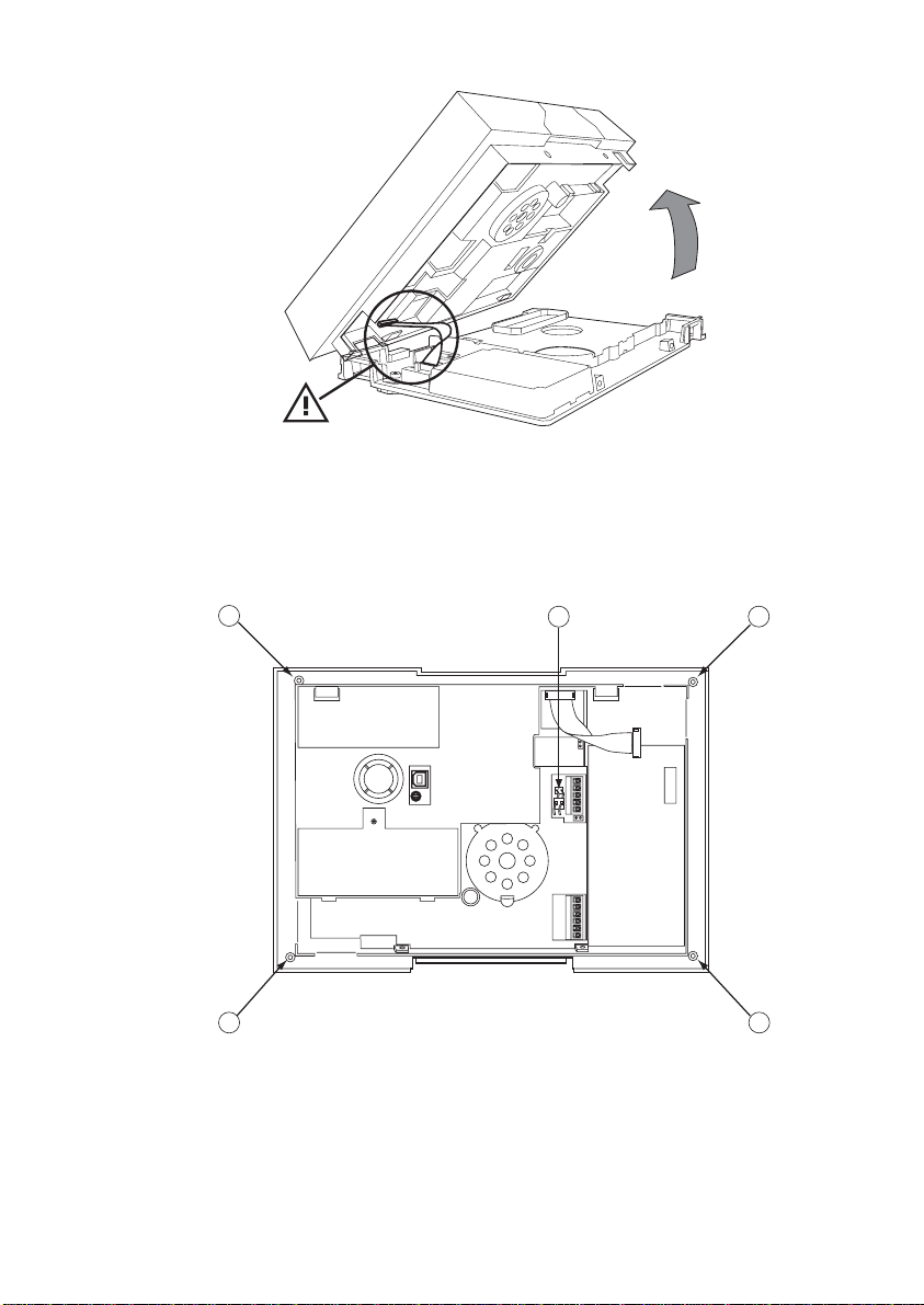
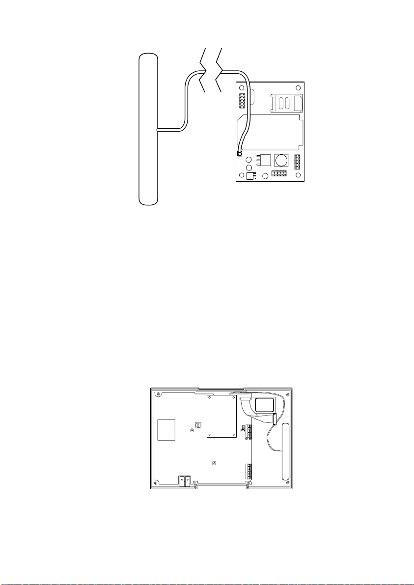
3. Use the control unit. You can temporarily fit the SIM card
and antenna to the 8844 and fit the 8844 module to the
control unit.
You can then register the SIM card (see page 13). However,
you should be aware that unless the SIM is registered, the
control unit will report the strength of the strongest network
signal. This may be an emergency network. (In the UK, all
networks must provide access to any mobile phone for
emergency calls.) Check that the 8844 SIM is registered
before checking the signal strength.
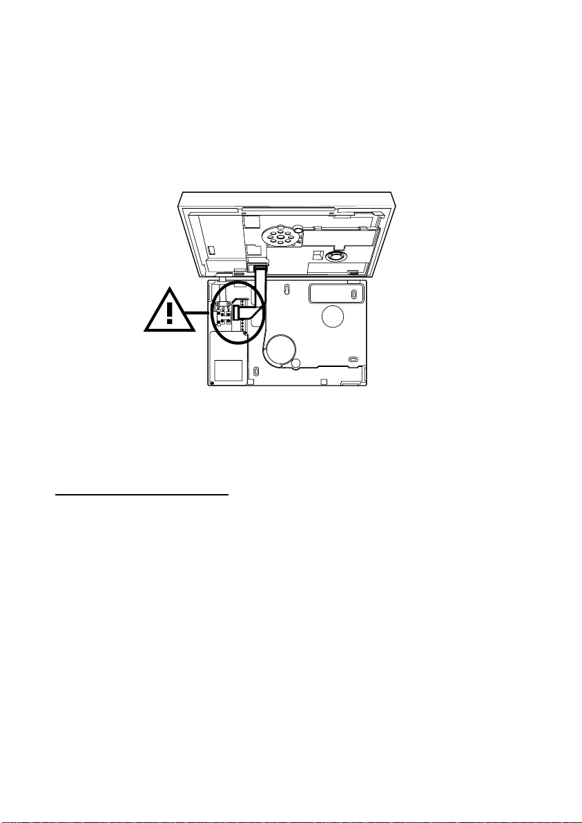
Caution: If you must remove the 8844 module from the
control unit take care not to bend the pins.
Dealing with poor signal strength
If the signal strength is poor, either:
Find a better antenna position.
Change the network SIM card to another provider.
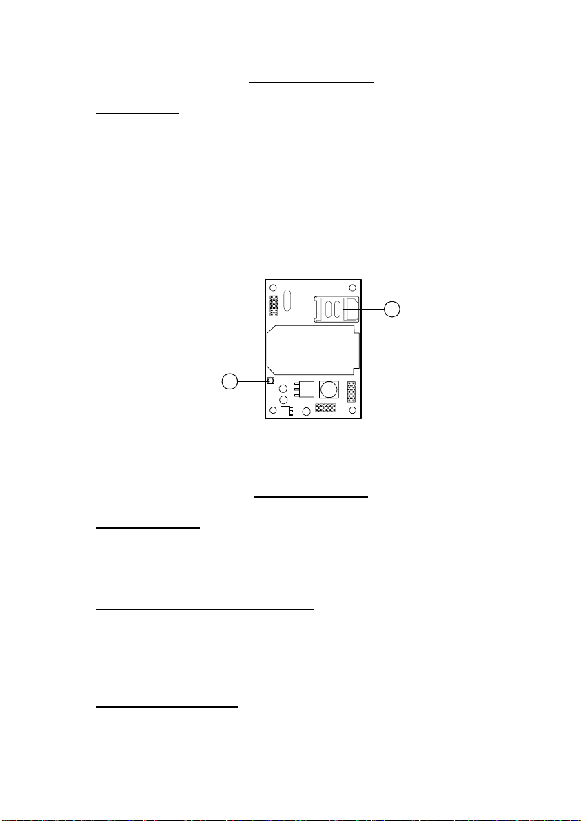
Preparing the 8844
1. Unpack the 8844 and its antenna.
2. Fit the SIM card for the provider you intend to use.
To release the SIM card holder slide the top cover

8844
6
towards the midline of the module, then pivot the cover
upwards.
Place the SIM card into the holder. Make sure the missing
corner on the card lies in the correct corner of the holder.
Close the SIM card cover and slide it back into place.
Make sure the cover clicks home.
Figure 3. Fit SIM Card
Fitting to a 7510r
Caution: If you are adding the 8844 to a control unit that
has already been installed then first make sure that the
system is completely unset and in installer programming
mode. (This is to prevent the control unit raising un-
necessary tamper alarms when you open the case.)
1. Undo the two screws at the bottom of the case.
Figure 4. Screw Locations
2. Ease the case body from the wall plate.
Caution: Disconnect the ribbon cable from the wall plate
before opening the case completely, see Figure 5.

8844
7
Figure 5. Internal Ribbon Cable
3. Undo all four screws holding the body of control unit
together. See 1 in Figure 6.
4. Disconnect the speaker and battery connectors (see 2 in
Figure 6).
1
1
1
1
2
1. Screw positions 2. Battery and Speaker Connectors
Figure 6. Screw Positions

8844
8
5. Partially lift the back of the case up and disconnect the
siren lead before completely removing the back of the
case. Figure 7 shows the layout of the main printed
circuit board (PCB).
2
4
3
110
8
5
7
6
9
1 Sockets for GPRS module 6 Kick Start jumper
2 USB connector 7 Reset codes jumper
3 Siren connector 8 Battery connector
4 Tamper switch 9 Speaker connector
5 Microphone 10 Tag reader
Figure 7. Main Printed Circuit Board.
6. If you are going to fit the antenna outside the case then
feed the plug end of the lead through one of the cable
entries in the wall plate. Next, feed the plug end of the
lead through the hole in the case back where the ribbon
cable exits.
7. Connect the antenna cable to the antenna input socket on
the module (see Figure 8). Ensure that you route the
antenna cable as shown.

8844
9
Figure 8. Connect Antenna Cable
8. Fit the module to the sockets on the control unit PCB (see
Figure 9).
9. Remove the backing paper on the glued side of the
antenna.
EITHER A) If you are fitting the antenna outside the case
place it in position.
OR B) If you are fitting the antenna inside the case then
fix the antenna inside the case as shown in Figure 9.
Note: The adhesive on the antenna is fast acting. You will not
be able to reposition the antenna once you have put it in
place.
Figure 9. Fit 8844 Module
9. Ensure that the antenna cable runs across the top of the
control unit pcb as shown in Figure 9.

8844
10
10. Present the back of the case to the case front and re-
connect the siren, battery and speaker. See Figure 7.
11. Seat the back of the case into the case front, making sure
that you do not crush the 8844 module antenna. Refit all
four screws holding the case together. See Figure 6.
12. Present the case to the wall plate and re-connect the
ribbon cable, see Figure 10.
Figure 10. Connect Ribbon Cable
13. Fit the case to the wall plate and refit the securing screws
(see Figure 4). Make sure that you do not crush the 8844
module antenna lead.
Fitting to an i–on40
Caution: If you are adding the 8844 to a control unit that
has already been installed then first make sure that the
system is completely unset and in installer programming
mode. (This is to prevent the control unit raising un-
necessary tamper alarms when you open the case.)
1. Remove mains power.
2. Open the control unit (see Figure 11 ).

8844
11
1
2
3
Figure 11. Opening the i-on40 Control Unit.
3. Disconnect the battery.
4. Feed the plug end of the aerial lead in from the outside of
the case through one of the cable entry holes. Do not use
the mains cable entry hole.
5. Connect the antenna cable to the antenna input socket on
the module (see Figure 12).
Figure 12. Connect Antenna Cable
6. Fit the 8844 to the plug on module sockets (see Figure 13).
Take care not to unseat the antenna lead connector. Do not
use excessive force when seating the module.

8844
12
Figure 13. Fitting I-8844 Module
7. Remove the backing paper on the glued side of the
antenna. Place the antenna in position.
Note: The adhesive on the antenna is fast acting. You will not
be able to reposition the antenna once you have put it in
place.
8. Re-connect the battery (the control unit will not start).
9. Re-fit the control unit lid.
Programming
Before programming the control unit please make sure that:
a) You have obtained the necessary information from your
GPRS Service Provider and ARC (APN number, username,
password and relevant IP addresses).
b) You have fitted a GPRS module.
Note: When keying in IP addresses, the address comprises
four groups of digits. Each group is three digits long, and
is separated from the next group by a “dot”, for example
“192.168.000.001”. Press “*” to key in the dot.
Programming Overview
1. Enter User mode and check that the module works.
2. Register your SIM card

8844
13
3. Enter Installer Mode and then carry out the following
steps:
a) Set up the GPRS hostname, username and password
assigned to the control unit. (The service provider will
supply the control unit with its own IP address during
connection.)
b) Set up the IP address of the ARC. This is the address
that the unit will report alarm information to.
c) If required, set the IP address and port number
belonging to the Downloader software.
The control unit also allows you to store two alternate
IP addresses for Downloader.
Checking that the Module Works
Apply power to the control unit.
Enter the User programming menu.
On the 7510r select System Config – About Comms.
On the i-on40 select About - Comms - Module: GPRS.
After short delay the display shows:
IMEI number for the module. You should note this number
down as you will need to provide it when you register your
SIM card with certain service providers.
Signal level. If the level is low you may need to reposition
the control unit, or seek another service provider.
GSM Network. A short text string or a multi-digit number
that identifies the network. If a “*” appears at the
beginning of the field then this indicates roaming access.
GSM Number. (This may not appear if you are using
Vodafone as a service provider.) Note this number down so
that you can supply it when registering your SIM card.
Page 15 provides space for you to record the IMEI and GSM
numbers.
Registering Your SIM Card
Once you have fitted the module and its SIM card, you must
register the SIM card with the service provider. To do this you
must make a telephone call from the control unit via the

8844
14
newly installed module (you could also do this from a
landline).
Enter the User programming menu and select Telephone Call –
GSM.
Dial the appropriate telephone number for registering the SIM
card as shown in the instruction leaflets for the card. (See
below.)
Note that the control unit cannot support the text message
response service calls using the * and # keys. You must call
the service provider manually and either register with a
human operator, or navigate an automated answering
service. Once the phone call is established you can use the *
and # keys as you would on a normal phone.
The exact details of registering your SIM card differ for each
provider. The following sections show hints for the main
providers.
O2
Note that 02 print the SIM serial number and the GSM
telephone number on the packing for the SIM card.
To register an 02 SIM dial 248 and follow the instructions
given by the automatic answering service.
T-Mobile
T-Mobile print the GPRS telephone number, PIN number and
PUK (unlock number) on the sheet carrying the SIM card and
top up card.
To register a T-Mobile SIM dial 150 and follow the instructions
given by the automatic answering service.
If you have several mobile phones fix the sticky label
provided showing the GPRS number to the top up card.
Orange
Make sure you have the GPRS module’s IMEI number to
hand. You will also need the SIM card serial number, it is
printed on the SIM card.
You will need to provide a password and four digit code to
identify yourself in the future. Chose them before making the
call and write them down in the booklet.

8844
15
To register an Orange SIM dial 0800 079 0006. A human
operator will reply.
While registering your SIM, the operator will provide you with
your GSM number. Make sure you note this number on the
top up card.
Vodafone
To register a Vodafone SIM dial 2345 and follow the
instructions given by the automatic answering service. During
the instructions you will be given your GSM number. Make
sure that you note this number down on the back of the top
up card.
Top Up Cards
Avoid using a pay as you go account. If you must, then be
aware that the 8844cannot warn you of low credit. Set up
regular top-ups for the account or manage it through the
internet (if the provider gives you that option).
Each of the service providers listed in the previous
instructions supply top up cards with their SIMs. Part of the
registration procedure is to link the top up card with the SIM.
The cards contain just enough credit to allow you to make the
registration call. Once you have finished this process you will
need to supply more credit to the top up card. You should do
this immediately.
While registering, make sure that you write the phone
number of the GPRS module down on the top up card.
The table below provides spaces for you record the relevant
information about your GPRS installation.
IMEI No.
SIM Card Serial No.
GSM No.
Top Up Card No.
Set Up GPRS Hostname, Username, and
Password
Enter Installer Mode.
On the 7510r select IP Network.

8844
16
On the i-on40 select Communications - IP Network - Module:
GPRS.
The display shows the following options:
IP Address Leave blank.
IP Port Number
Leave blank.
Note: When delivered from the factory, the control unit
contains no IP address; it will obtain its own IP address
from the service provider.
GPRS APN (Access Point Name) Key in the text of the
access point name.
GPRS Username
Key in your GPRS user name.
GPRS Password
Key in your GPRS password.
Set Up the IP Address of the ARC
The ARC must have the IRIS receiver software running in
order to receive data from the 8844.
When communicating with the alarm message receiver at the
ARC you can specify two IP addresses. The control unit sends
data to the second ARC IP address if a call to the first ARC IP
address fails (and you have selected Alternate in Reporting,
Alarms, Call Mode.)
In addition, you must store a string of characters that the
receivers use to identify every individual control unit. This
identifier is independent of the ARC account numbers.
To set up the IP address of the ARC:
On the 7510r select Reporting - Alarms - IP Network.
On the i-on40 select Communications - ARC Reporting - IP
Network.
The display shows the following options:
Unit name Select this option and key in a string of up to

8844
17
32 characters. This string must be unique for
each control unit communicating to a receiver.
Polling Eng IP Address
Key in the IP address of the IRIS polling
engine.
ARC IP Address 1
Key in the ARC’s main IP address.
Note that this option also allows you to key in a
unique identifying name for the ARC.
ARC IP Address 2
Key in the ARC’s alternate IP address.
This option also allows you to key in a unique
identifying name for the ARC.
Note: On the i-on40 ARC IP Addresses 1 and 2 both appear
under a single menu item “ARC IP Address”.
Setting up for Downloader
While connected Downloader can inspect and/or change the
control unit’s programming configuration. If you do not wish
to change the configuration you can simply monitor the state
of the control unit and its zones from the PC.
To use Downloader software over an IP connection you must
store two IP addresses that the control unit can “call” in order
to start a Downloading session. The user starts the call by
selecting one of the IP address.
To program the Downloader IP address:
On the 7510r select Downloading - IP Network.
On the i-on40 select: Communications - Downloading - IP
Network.
The options available are:
IP Address 1 Key in the IP Address used by Downloader.
IP Port 1 Key in the port number that Downloader
“listens” to on the remote PC at IP address 1.

8844
18
IP Address 2 Key in an alternate IP Address used by
Downloader.
IP Port 2 Key in the port number used by the alternate IP
address.
Note: On the i-on40 both IP Addresses are under a single
menu and both IP Ports are under a single menu.
To set up the control unit’s own IP address:
On the 7510r select IP Network.
On the i-on40 select: Communications – IP Network (Own).
The options available are:
IP Address This is the control unit’s own IP address.
Sub-Net Mask
If necessary, key in the sub-net mask.
Note: If you leave IP Address and Sub-Net Mask blank then
the control unit will use DHCP (Dynamic Host Control
Protocol) to obtain these values from a DHCP server.
Gateway Address
This is the IP address of the router that
connects the local network, to which the i-on40
is connected, to rest of the Internet (or to a
larger network).If necessary, key in the
gateway IP address.

8844
19
Notes:

8844
20
Cooper Security Ltd.
Security House
Vantage Point Business Village
Mitcheldean
Gloucestershire
GL17 0SZ
www.coopersecurity.co.uk
Product Support (UK) Tel: +44 (0) 1594 541979.
Available between:
08:15-12:30 and 13:00-17:00 Monday to Friday.
Product Support Fax: (01594) 545401
Part Number 11954954 Issue 1
Table of contents
Other Cooper Control Unit manuals

Cooper
Cooper Scantronic 9 5 Series Operating instructions

Cooper
Cooper Z-WAVE RF232 User manual

Cooper
Cooper CEAG Webmodule ZB-S User manual

Cooper
Cooper Scantronic 95 User manual

Cooper
Cooper Scantronic 770r User manual

Cooper
Cooper 9930 User manual

Cooper
Cooper F6-PA-LS User manual

Cooper
Cooper S280-79-10 User manual

Cooper
Cooper Crouse-Hinds IF 1589 Setup guide

Cooper
Cooper Scantronic 65 User manual