TRILETY MCK User manual

Gebrüder TRILETY Ges.m.b.H. MCK-M31 1.02 09/ 2018
* Optional equipment Page
1
INSTRUCTION MANUAL
STREET CLEANER
MCK FOR MULTICAR FUMO/ M31
Specifications
Operating Instructions
Maintenance
List of Spare Parts

Gebrüder TRILETY Ges.m.b.H. MCK-M31 1.02 09/ 2018
* Optional equipment Page
2
TABLE OF CONTENTS
1
SPECIFICATIONS ...............................................................................................4
1.1
TECHNICAL DATA ...............................................................................................................................4
1.2
Technical Description ..............................................................................................................................5
1.3
Construction And Function ....................................................................................................................5
1.4
Base Framework ......................................................................................................................................6
1.5
Hopper ......................................................................................................................................................6
1.6
Water Tank ..............................................................................................................................................6
1.7
Suction Fan Unit ......................................................................................................................................7
1.8
Sweeping and Suction Unit .....................................................................................................................7
1.9
Front Disk Brush (Optional Equipment) ...............................................................................................8
1.10
Hydraulic System ................................................................................................................................9
1.11
Electric System ....................................................................................................................................9
1.12
Spray Water System .........................................................................................................................10
1.13
Operation Principle...........................................................................................................................11
2
OPERATING INSTRUCTIONS ..........................................................................12
2.1
SAFETY TIPS........................................................................................................................................12
2.2
PREPARATION OF THE Multicar CHASSIS ..................................................................................14
2.3
MOUNTING AND DEMOUNTING THE SWEEPER ......................................................................14
2.3.1
Mounting the Sweeper Unit............................................................................................................14
2.3.2
Demounting the Sweeper Unit........................................................................................................16
2.4
Sweeping operation................................................................................................................................18
2.4.1
Filling the spray-water tank............................................................................................................18
2.4.2
Controls Multicar Vehicle ..............................................................................................................19
2.4.3
Control panel MCK sweeper..........................................................................................................21
2.4.4
Information for operating the vehicle:............................................................................................21
2.4.5
Starting the sweeping operation .....................................................................................................22
2.4.6
General information for sweeping ..................................................................................................23
2.4.7
Used Water Drainage .....................................................................................................................24
2.4.8
Concluding the sweeping operation................................................................................................25
2.4.9
Dumping.........................................................................................................................................26
2.4.10
Working with the Hand Suction Hose .......................................................................................29
2.4.11
Using the High Pressure Water Unit..........................................................................................32
2.4.12
Pressure Adjustment ..................................................................................................................34

Gebrüder TRILETY Ges.m.b.H. MCK-M31 1.02 09/ 2018
* Optional equipment Page
3
3
MAINTENANCE .................................................................................................35
3.1
Chassis and engine .................................................................................................................................35
3.2
Hopper ....................................................................................................................................................35
3.2.1
Baffle Plate.....................................................................................................................................35
3.2.2
Filter Screens..................................................................................................................................35
3.2.3
Wastewater filter screen .................................................................................................................36
3.2.4
Air Ducts ........................................................................................................................................36
3.2.5
Safety Bar.......................................................................................................................................36
3.3
Spray water system................................................................................................................................37
3.3.1
Working in Freezing Temperatures................................................................................................37
3.3.2
Water Tank.....................................................................................................................................37
3.3.3
Water Pump....................................................................................................................................37
3.3.4
Water Filter ....................................................................................................................................38
3.4
Suction fan..............................................................................................................................................38
3.4.1
Cleaning .........................................................................................................................................38
3.4.2
Fan Impeller Bearing......................................................................................................................39
3.5
Sweeping and suction unit.....................................................................................................................40
3.5.1
Basic Settings .................................................................................................................................40
3.5.1.1
Suction Hood ........................................................................................................................40
3.5.1.2
Disk Brush ............................................................................................................................41
3.5.2
Adjustments....................................................................................................................................43
3.5.2.1
Suction Hood ........................................................................................................................43
3.5.2.2
Disk Brush ............................................................................................................................43
3.5.2.3
Front Brush* .........................................................................................................................45
3.6
Hydraulic system....................................................................................................................................46
3.6.1
Safety Tips .....................................................................................................................................46
3.6.2
General Information .......................................................................................................................46
3.6.3
Checking the Hydraulic Oil Level ..................................................................................................47
3.6.4
Checking the Hydraulic Oil Temperature.......................................................................................47
3.6.5
Checking the Hydraulic Filter ........................................................................................................47
3.6.6
Bleeding the Hydraulic System ......................................................................................................48
3.7
Troubleshooting .....................................................................................................................................49
3.7.1
Sweeping and Suction Gear............................................................................................................49
3.7.2
Hydraulic System ...........................................................................................................................51
3.8
Maintenance schedule............................................................................................................................52
4
LIST OF SPARE PARTS ...................................................................................56
Gebrüder TRILETY Ges.m.b.H. MCK-M31 1.02 09/ 2018
* Optional equipment Page
4
1 SPECIFICATIONS
1.1 TECHNICAL DATA
Permitted total weight 4,800 kg
Hopper capacity 2,2 m
3
Water tank capacity** 370 l
Sweeping width with standard brush gear (2 brushes) max. 2,000 mm
Sweeping width with additional front brush max. 2,600 mm
Suction fan capacity max. 8,000 m
3
/h
Suction fan speed max. 3,000 rpm
Suction vacuum during sweeping approx. 550 mm WS
Maximum suction vacuum approx. 1,100 mm WS
Sweeping speed approx. 0...15 km/h
Vehicle length without front brush approx. 5,200 mm
Vehicle length with front brush approx. 6,300 mm
Vehicle width 1,600 mm
Vehicle height approx. 2,100 mm
Total weight without optional equipment approx. 3,180 kg
Payload approx.1,620 kg
Noise level at engine speed 1,800 rpm 78.5 dB(A) Mean value
Noise level at the driver’s position, window closed 76.8 dB(A)
Noise level at the driver’s position, window open 77.4 dB(A)
The sweeper unit should be only used to clean the street surface, park places,
underground garages and other solid surfaces and to suck out canal ducts.
The sweeper must not be used for picking up material that are explosive,
inflammable or which may constitute a health hazard!
Any alterations to the construction of the sweeper unit can only preformed after
they have been authorized by the manufacture.

Gebrüder TRILETY Ges.m.b.H. MCK-M31 1.02 09/ 2018
* Optional equipment Page
5
1.2 Technical Description
The sweeper MCK is designed as an exchangeable unit for Multicar chasses and is
partly constructed out of stainless steel (hopper, water tank). The sweeper may be used
for cleaning roads, car parks, large public and industrial areas, etc. All the important
working functions are controlled by the driver in the cab. In addition, a video system to
monitor the rear working area (optional equipment) can be fitted onto the rear of the
vehicle.
Large objects, such as stones, tins, bottles etc., can be picked up through an
automatically working, remote-controlled* bulky debris pick-up flap.
To meet a wide variety of requirements, the exchangeable sweeper unit may be fitted
with a number of optional features:
•Front mounted 3
rd
brush for an increased sweeping width and for sweeping out road
bays and sloping kerbs.
•Rear mounted hand suction hose to empty gully holes or sucking up leaves
•Hopper made entirely of aluminium (Weight saving approx. 300 kg)
•Spotlights for sweeping in the night
•Rotating flashing beacon on the hopper roof
•Rear view camera with monitor in the cab
1.3 Construction And Function
The entire sweeper unit consists out of the following:
Base Framework
Hopper
Fan Unit
Water Tank
Sweeping and Suction unit
Option Front Brush Unit
The entire sweeper unit can be fitted onto the ball joints of the Multicar M26 chassis
using a few easy steps.
The hopper is located at the rear of the sweeper unit.
The suction fan and the fan motor are located at the front of the sweeper unit.
The water tank is built under the suction fan into the frame.
The sweeping and suction unit is mounted onto a swivelling arm at the rear of the
sweeper unit.
A large storage basket is built into the frame under the hopper.
The sweeping and suction functions, including the hopper tipping control, are controlled
through the:
•Multicar hydraulic system
•Electrical system

Gebrüder TRILETY Ges.m.b.H. MCK-M31 1.02 09/ 2018
* Optional equipment Page
6
1.4 Base Framework
The entire sweeper unit is construction onto a robust base framework fabricated out of
rectangular tubes. The base framework can be mounted onto the ball joints of the
vehicle chassis.
Extra holding tubes are fitted into the base framework, to strengthen the construction
and to allow that support legs can be inserted.
The front section of the sweeper unit contains the water tank and the machinery
compartment which is lined with sound absorbing material.
A storage basket is built into the middle part of the base framework.
1.5 Hopper
The hopper is made out of stainless steel (optional Aluminium) and is mounted onto the
base framework using robust bearing blocks.
The hopper capacity is approx. 2,2 m
3
.
Observation flaps has been set into each side of the hopper, so that the fill volume can
be controlled and to allow that bulky objects, which cannot be picked up by the suction
hood, can be manually thrown into the hopper.
A wear-resistant elastic spiral hose, 220 mm in diameter, connects the suction hood to
the hopper.
A rubber-lined baffle plate is installed above the suction air inlet of the hopper. The
sucked air then flows via the filter plates fitted on the upper right and left-hand sides of
the hopper through the air duct into the suction fan and then is dispersed over the
exhaust-air duct.
The contents of the hopper are emptied through a large flap that covers the entire rear
side of the hopper. The flap is closed by hand, the flap is opened kept in the opened
position using gas filled spring cylinders.
The locking mechanism for the closed flap is operated using an electric motor.
The hopper is tipped by using 2 hydraulic cylinders; through the high position of the
bearing blocks a tipping height of approx. 1,450 mm is obtained. The tipped hopper can
be secured using the supplied safety support bar.
1.6 Water Tank
The water tank is made of stainless steel and is mounted at the front end of the base
framework. The tank capacity is approx. 370 l (250 l with low-height models).
The tank is filling system is fitted with a Storz-C-coupling connection and contains an
anti backflow system. The water level can be seen on the water level gauge. A water-
level indicator in the cab* is available as an optional equipment.

Gebrüder TRILETY Ges.m.b.H. MCK-M31 1.02 09/ 2018
* Optional equipment Page
7
1.7 Suction Fan Unit
The suction fan unit is mounted, elastically supported, at the front end of the base
framework.
The suction fan unit is fitted with high-performance suction fan blade which has been
designed to obtain an optional suction efficiency for the sweepings.
The suction fan is driven by a hydraulic axial piston motor which is flange-mounted onto
the suction fan unit. The hydraulic motor is driven by the hydraulic oil supplied by the
hydraulic system of the Multicar chassis.
The exhaust air of the suction fan is so dispersed underneath the sweeper body, that
there is no annoyance from the air flow, even in the immediate vicinity of the sweeper.
1.8 Sweeping and Suction Unit
The sweeping and suction gear is mounted onto a swivelling frame on the rear side of
the base framework and consists of:
•Swivelling arm (allows sweeping and suction unit to be swivelled to the side of the
vehicle when the hopper is emptied)
•Lifting arm (lifts and lowers the sweeping and suction unit)
•Floating arm (automatically adjusts so the sweeping and suction units are parallel to
the road surface even when the road slopes)
•Suction hood with suction hose
•Bulky debris pick-up flap
•2 disk brush units
The suction hood with suction hose is mounted in the middle of the floating arm.
The bulky debris pick-up flap is located in front of the suction hood.
The disk brush units are mounted onto the right and left sides of the floating arm and
their height can be adjusted by hand; the brushes can also be swivelled outwards.
While sweeping, the floating arm is trailed behind the vehicle on two robust large
support wheels (∅250mm). The sweeping and suction unit on the floating arm are
raised from the road surface by a hydraulic cylinder on the lifting arm.
When the hopper is to be emptied, the complete sweeping and suction unit is swivelled
to the side of the vehicle using the swivelling arm.
To reduce the quantity of dust raised while sweeping, all sweeping and suction units are
fitted with a spray water nozzles.
Gebrüder TRILETY Ges.m.b.H. MCK-M31 1.02 09/ 2018
* Optional equipment Page
8
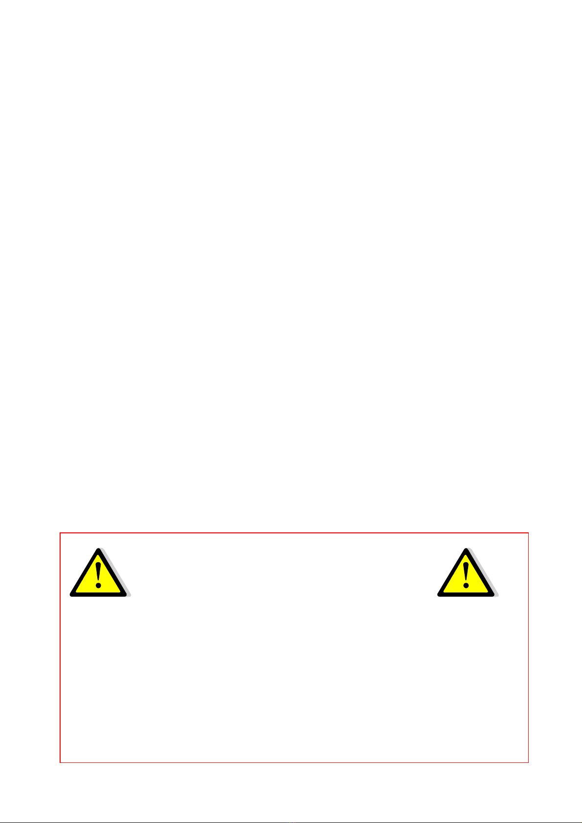
1.9 Front Disk Brush (Optional Equipment)
To increase the swept width and to facilitate sweeping along kerbstones and sloping
kerbs, the sweeper can be fitted with a front brush unit.
The front disk brush is mounted onto the vehicles front mounting plate and consists of
the following:
−Mounting plate
−Telescoping arm or swivelling arm (depending on the model)
−Disk brush unit
The swivelling and height-adjustable disk brush unit is mounted onto a telescoping or
swivelling arm. The brush unit is extended or swivelled by means of a hydraulic
cylinder. The front brush is lifted via the vehicles front mounting plate.

Gebrüder TRILETY Ges.m.b.H. MCK-M31 1.02 09/ 2018
* Optional equipment Page
9
1.10 Hydraulic System
Max. flow volume in the brush drive circuit 18 l (can be adjusted on the
solenoid valve block of the chassis. The volume is preset and should not be altered)
The hydraulic circuits are connected to the hydraulic system of the Multicar chassis
using quick release couplings and control the following functions:
•Suction fan drive
•Disk brush drive
•Tipping of the hopper
•Front brush* drive
•Extending of front brush*
These functions are controlled using the control elements of the Multicar chassis in the
cab or using the switches on the separate control panel for the sweeper unit.
1.11 Electric System
All electrical contacts, plug and sockets that are used for the connections
between the vehicle and the sweeper unit are to be weekly sprayed with a
commercial contact spray to prevent corrosion and the possibility of error
conditions.
The sweeper is fitted with a 12-volt electric system.
The power is supplied via the electric system of the Multicar M26 chassis and regulates
the following functions:
•Water pump drive
•Solenoid valves for the spray water
•Solenoid valves for the brush drive controls
•Rear flap locking device
•Remote control bulky debris pick-up flap*
•Spotlights for control of the brushes *
•Rotating flashing beacon on the hopper roof*
The controls for these functions are located on the separate control panel of the
sweeper unit.

Gebrüder TRILETY Ges.m.b.H. MCK-M31 1.02 09/ 2018
* Optional equipment Page
10
1.12 Spray Water System
The spray water system is fitted to reduce the quantity of dust raised during the
sweeping operation and helps to separate the dust from the sucked debris in the
hopper.
The standard delivered hand spray pistol and hose are used to clean the discharge flap
sealing and the interior of the hopper after dumping.
The water is separately supplied via solenoid valves, to the suction hood, disk brushes
and front brush*.
The spray water system consists of:
•Water tank, 370 l (250 l with low-height models)
•Water filling equipment
•Water drainage equipment
•Water filter
•Water pump, electrically powered
•Overpressure valve
•Solenoid valves, to actuate the spray nozzles
•Spray nozzles:
Disk brushes 2 nozzles each brush
Suction hood 5 nozzles
Front brush* 4 nozzles
•Water filling hose with C-coupling and hydrant key
•Water hose with spray pistol
The water tank is filled using a pressureless none return flow system, which conforms
to the requirements of the “protection of drinking water from contamination in water
supply systems“.
The water level in the water tank can be controlled using the water level gauge.
The electrical water pump (dry running safe) is designed so that it will not be damaged
when running without water. The pump delivers a volume of approx. 15 l/min. While
sweeping, the water pressure of the spray water system is adjusted to max. 2 bar. The
water hose and spray pistol can be connected to the sweeper unit using the quick
release coupling for the water to the suction hood.

Gebrüder TRILETY Ges.m.b.H. MCK-M31 1.02 09/ 2018
* Optional equipment Page
11
1.13 Operation Principle
As the vehicle drives, the disk brushes sweep the debris in front of the suction hood.
The swept width can be increased by actuating the front brush* (optional equipment).
The front brush also facilitates the sweeping of road bays and between parked cars.
To reduce the quantity of dust raised while sweeping, the debris is sprayed with water
by means of spray nozzles fitted onto the sweeping and suction units.
The suction fan generates a vacuum in the hopper, this vacuum then sucks the
sweeping through the suction hood and the flexible suction hose into the hopper.
Due to the much larger cross-section in the hopper, the speed of the sucked air is
considerably reduced and the debris then settles in the hopper. A rubber-lined baffle
plate, fitted above the suction connection piece in the hopper, protects the hopper roof
from damage.
The suction fan then sucks the air, free from the sweeping through the filter screens
and then blows it into the exhaust air duct. The filter screens prevent that bulky but light
debris (paper, leaves etc.) are not sucked into the suction fan.

Gebrüder TRILETY Ges.m.b.H. MCK-M31 1.02 09/ 2018
* Optional equipment Page
12
2 OPERATING INSTRUCTIONS
2.1 SAFETY TIPS
The sweeper may only be operated by trained personnel!
The safety support bar must be inserted under all circumstances when
working underneath the tipped hopper!
Before starting work inside the hopper, open the discharge flap as wide as
possible; remove the vehicle’s ignition key and keep it an a safe place,
inaccessible for other people!
While the hopper is being lowered ensure that no persons are within the
danger zone of the equipment!
The person activating the tipper control must ensure that the area is clear,
before and during the procedure for lowering the hopper!
The hopper should be only tipped when the discharge flap lock is open – even
if the hopper is partly filled!
Maintenance on the suction fan should only be performed after the fan impeller
has stopped . For safety reasons, the ignition key of the vehicle should be
removed and kept in a safe place that is inaccessible for other people.
Before driving the vehicle, ensure that the rear sweeping and suction unit is
correctly positioned and locked onto the vehicle also ensure that the brushes
are in the raised position and secured with the steel cable!
Before driving the vehicle, ensure that the front brush is completely retrieved
and the brush is raised and locked in the raised position with the locking pin!
Internal-combustion engines must not be kept running in closed or narrow
spaces – danger of exhaust gas poisoning!
The vehicle must not be overloaded!
The vehicle should not be driven with raised hopper!
The sweeper must not be used for picking up material that are explosive,
inflammable or which may constitute a health hazard!
The hand spray pistol must not be directed at people, or at objects that contain
electricity!

Gebrüder TRILETY Ges.m.b.H. MCK-M31 1.02 09/ 2018
* Optional equipment Page
13
Special care is necessary when mounting / removing the sweeper unit onto /
from the vehicle chassis!
Note:
Additionally the safety tips specified in the following chapters must also be observed
under all circumstances!
Note:
In addition, the safety regulations for operating the vehicle must also be observed under
all circumstances (see separate manual!)!
The information left and right are always related to the direction of travel (forward drive)

Gebrüder TRILETY Ges.m.b.H. MCK-M31 1.02 09/ 2018
* Optional equipment Page
14
2.2 PREPARATION OF THE MULTICAR CHASSIS
The Multicar chassis that is to serve as the carrier vehicle must be suitable for the
exchangeable sweeper body and must be specially adapted for the sweeper body with
the following equipment:
•07-4 power hydraulic
•Hydraulic connections for operating the sweeper unit
•Electric connections for the sweeper and controls in the cab
•Water pipes for front brush
2.3 MOUNTING AND DEMOUNTING THE SWEEPER
The exchangeable sweeper MCK is designed as a quick-swap body for Multicar
chasses and can be easily and quickly mounted onto a Multicar chassis that has been
pre-fitted with the appropriate equipment with a few easy steps:
To ensure easy connection, the supply lines and cables (hydraulics, electrics, water)
are fitted with quick release couplings.
! Caution !
Special care should be taken when changing the attachment – high risk of
accidents by incorrect performance!
2.3.1 Mounting the Sweeper Unit
1. Remove the tipping platform from the vehicle using the vehicle manufacturer
instructions.
! Caution !
To prevent damage to the sweeper unit, the vehicles tipping cylinder
disconnected from the vehicle hydraulics!
2. Raise the front mounting plate completely.
3. Insert the connection between the hydraulic pressure coupling and the
pressure transfer to the rear on the front (only applies if brush drive circuit
is not at the rear or without frontbrush = pressure forwarding)
Gebrüder TRILETY Ges.m.b.H. MCK-M31 1.02 09/ 2018
* Optional equipment Page
15
4. Wind up the 4 sweeper unit support legs, so that the sweeper unit is in a
position that ensures that the vehicle can be driven underneath without
touching the sweeper unit.
5. Drive the vehicle underneath the sweeper unit and position the vehicle so
that the ball joints are underneath the ball joint receptacles.
6. Connect the sweeper unit hopper tipping hydraulic hose connections to the
quick release couplings for the vehicle tipping cylinder.
7. Evenly lower the sweeper body onto the vehicles ball joints by winding down
the 4 support legs. Ensure that all the ball joints are correctly inserted in the
receptacles. Insert the safety pins underneath the ball joints.
8. Remove the support legs from the holding tubes and store them.
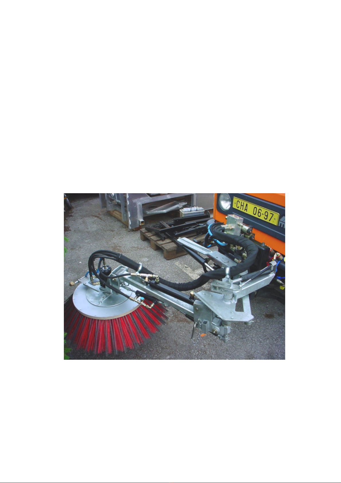
9. Connect the hydraulic hoses for the suction fan on to the connectors on the
right hand side behind the drivers cab.
10. Connect Leakoil.
11. At the rear of the vehicle, connect the hydraulic hose quick release
connections according to the numbering (or description)
12. Connect the 7-pin electrical plug for the additional Road Traffic Licensing
Regulations lighting onto the socket on the rear of the vehicle.
13. Connect the electrical plug for the connecting cable onto the socket at the
rear of the vehicle or place the control panel into the cab through the rear
window (depending on the model).
Connect here
hydraulic-tube for
suction unit lifting
(coupling for tipping
cylinder)
leakoil

Gebrüder TRILETY Ges.m.b.H. MCK-M31 1.02 09/ 2018
* Optional equipment Page
16
Model with Front brush
14. Connect the water pipe to the connection at the rear of the vehicle.
15. Lower the front mounting plate and drive the vehicle to the mating plate of
the front brush.
16. Hook the mating plate of the front brush into the front mounting plate.
17. Raise the front mounting plate completely, ensure that location pins are the
inserted into the location holes at the top of the mating plate.
18. Swing in and tighten the retaining screws on the left and right hand side of
the mating plate.
19. Connect the hydraulic couplings and water pipe at the front of the vehicle.
2.3.2 Demounting the Sweeper Unit
Ensure that the removed sweeper unit will be stored on an even and stable
surface.
Before demounting the sweeper unit, completely empty the hopper and the water
tanks and thoroughly clean the brushes and the hopper.
1. Drive the Multicar vehicle with mounted sweeper to a parking area with firm,
level ground.
2. Before driving the vehicle, ensure that the rear sweeping and suction unit is
correctly positioned and locked onto the vehicle also ensure that the brushes
are in the raised position and secured with the steel cable.
3. Turn off the vehicle.
4. At the rear of the vehicle, disconnect the hydraulic quick release couplings,
place dust covers over the disconnected hydraulic couplings.
5. Disconnect the all the electrical plugs at the rear side (1 or 2 pcs., depending
on the model).
6. On the left and right hand side behind the drivers cab, disconnect the
hydraulic hoses for the suction fan and place dust covers over the
disconnected hydraulic couplings.
7. Insert the 4 support legs into the holding tubes. Remove the safety pins from
under the ball joints.

Gebrüder TRILETY Ges.m.b.H. MCK-M31 1.02 09/ 2018
* Optional equipment Page
17
8. Evenly wind up the support legs so that the sweeper unit is raised from the
vehicle. Lift the sweeper unit as high as necessary to ensure that the vehicle
can be driven away without touching the sweeper unit.
9. Disconnect the sweeper unit hopper tipping hydraulic hose connections to
the quick release couplings for the vehicle tipping cylinder.
10. Ensure that all connections to the vehicle are disconnected and that all the
hydraulic hoses, pipes and cables are so placed that they do not hinder the
vehicle's removal.
11. Start the vehicle.
12. Drive the vehicle away from underneath the sweeper unit that is supported
by the support legs.
13. Turn off the vehicle.
14. Reconnect the vehicle tipping cylinder to the vehicle hydraulic system.
15. Mount the tipping platform to the vehicle using the vehicle manufacturer
instructions.
Model with Front brush
16. Disconnect the hydraulic couplings and water pipe at the front of the vehicle.
17. Loosen and swing out the retaining screws on the left and right hand side of
the mating plate.
18. Lower the front mounting plate until the mating plate of the front brush is
completely disengaged from the mounting plate.
19. Drive the vehicle a short distance away from the front brush unit.
20. Raise the front mount plate completely and insert the fastening bolt for the
front mount plate to lock the plate.
20. Disconnect the water pipe to the connection at the rear of the vehicle.
Note:
When uncoupling the connections, check if any markings have become illegible
or have been lost; renew the markings, if necessary. To protect the disconnected
hydraulic couplings ensure that the dust covers are fitted.

Gebrüder TRILETY Ges.m.b.H. MCK-M31 1.02 09/ 2018
* Optional equipment Page
18
2.4 SWEEPING OPERATION
! CAUTION !
Vehicles and sweeper units which are not roadworthy and could malfunction
should not be put into operation!
The following items should be controlled each time before operating:
•The sweeper unit is correct mounted and fixed on the ball joints and that the front
brush is correctly mounted on the front mounting plate.
•Water level in the spray-water tank
•Adjustment of the sweeping and suction units
- brush load pressure
- height adjustment of the suction hood rubber strips
- wear of the brushes, suction hoses, rubber strips and rubber aprons
Before starting the sweeping operation, it is essential to observe the safety
instructions in accordance with point 2.1!
2.4.1 Filling the spray-water tank
1. Drive the sweeper to a hydrant with a C-coupling connection.
2. Open the locking system that locks the suction hose of the rear sweeping unit
on to the connection piece of the rear flap of the hopper.
3. Disconnect the suction hose from the hopper and hang it on the hook of the
sweeping unit.
4. Tip the hopper up a little, so that the items in the storage basket can be
reached. Caution for sweeping and suction unit.
5. Switch the vehicle off.
6. Remove the blank cover from the hydrant, open the hydrant for a short time
to wash any accumulated dirt away so that this dirt can not enter the water
tank.
7. Remove the blank cover from the water inlet port on the front right-hand side.
8. Place the water filter* on the hydrant connection and connect the water filling
hose to the water inlet port and water filter.
9. Open the hydrant valve.
Note: To limit the filling speed, the filling pipes have a reduced cross section.
10. Check the filling process on the water level gauge.
11. Fill in water until water exits out of the overflow of the water tank. Then
immediately close the hydrant.
12. Disconnect the water filling hose first from the water filter, then from the water
inlet port; roll up and store the hose in the storage basket.
13. Disconnect the water filter* from the hydrant, then reconnect the filter in the
reverse direction and rinse the filter for a short time by opening the hydrant.
14. Disconnect and store the water filter* in the storage basket.
15. Reattach all blank covers.
16. Switch the vehicle on.
17. Lower the hopper.
18. Reconnect the suction hose to the hopper.

Gebrüder TRILETY Ges.m.b.H. MCK-M31 1.02 09/ 2018
* Optional equipment Page
19
2.4.2 Controls Multicar Vehicle
The controls for the vehicle can vary according to options from Multicar carrier vehicle
(see original multicar manual) Adjust hydraulic flow with regulator in cabin or on
hydraulic block (right side behind drivers cab)
Hydraulic oil quantities: Suction fan appr.50 .... 55 l/min
Actuators and actuating functions 13 .... 15 l/min
For settings, see operating instructions Multicar chassis!
4.Brush drive
ON / OFF
3.Suction Fan
ON / OFF
2.Hydraulic system
ON / OFF
1. Hydraulik
drive on
Adjust vehicle
motorspeed

Gebrüder TRILETY Ges.m.b.H. MCK-M31 1.02 09/ 2018
* Optional equipment Page
20
Speedregulator brushes
adjust 12...15 l/min
Speedregulator suction
fan adjust 55 l/min
Frontbrush
raise/lower
Frontbrush
left-right and
slope
Adjust on
hydraulic valve
block on left side
beside battery
This manual suits for next models
1
Table of contents


