Trimax Genuine Parts Stealth S3 User manual
1
SPARE PARTS
INSTRUCTIONS # 48
Date Created: 20/04/2017
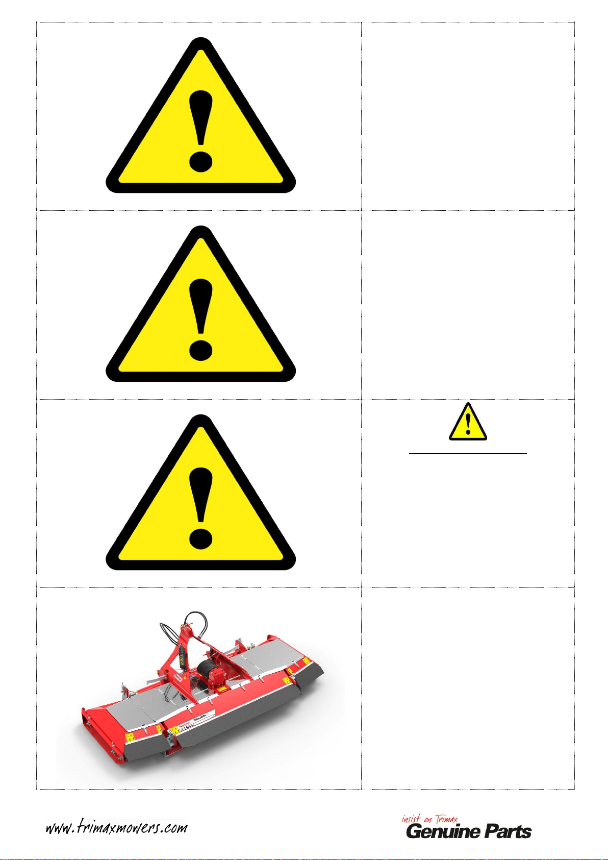
Product: Stealth S3
Title: Gearbox removal and replacement
SAFETY! Before attempting to make any adjustments or carry out maintenance on the mower, review
the hazard identification table (section 3a of your Operators Manual) and take all necessary precautions.
Lower the Stealth S3 onto the ground.
Raise the Transport Locks.
Lower the Wings down onto the ground.
Note:
Ensure the Tractor P.T.O is disengaged
and the Tractor is turned off!
Remove the P.T.O Shaft connecting the
Tractor to the Stealth S3.
Place to one side.
Please see the Operators Manual for
further detail if required!
Remove the four M12 Nyloc Nuts used
to secure the Centre Covers.
Place these to one side for re-fitment
later.
Unlatch ALL Covers.
Remove ALL Covers and place to one
side.
2
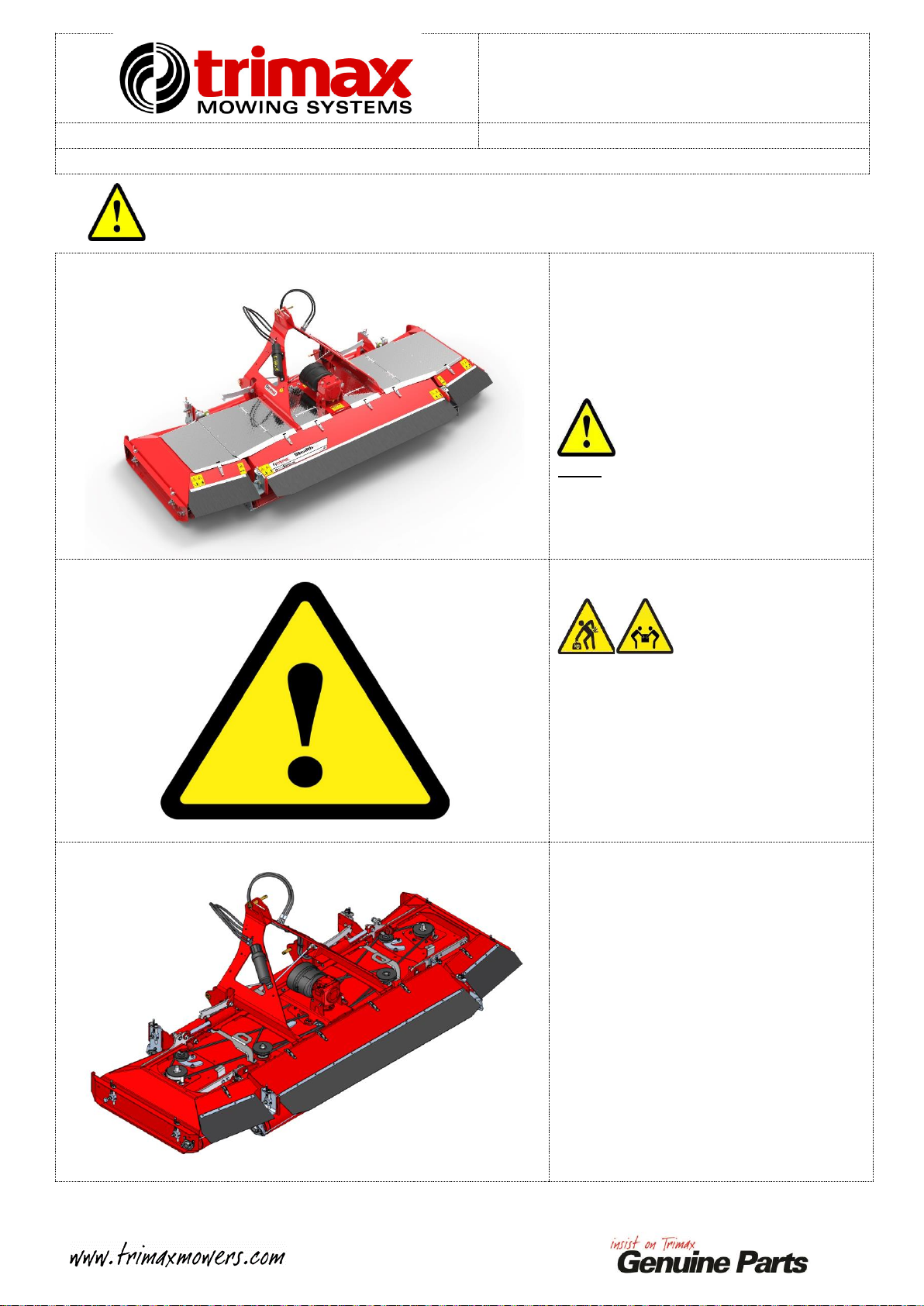
Remove the SHORT Left-Hand
Gearbox Belt Guide.
Place the M12 Nyloc Nuts and Belt
Guide to one side.
Note:
The Left and Right Hand Gearbox Belt
Guides are different from each other!
See inset for detail!
Remove the TALL Right-Hand Gearbox
Belt Guide.
Place the M12 Nyloc Nuts and Belt
Guide to one side.
Note:
The Left and Right Hand Gearbox Belt
Guides are different from each other!
See inset for detail!
Slacken ALL Idler Mounting Nuts.
One Idler shown.
Back the Idlers off to relieve belt
tension.
See below for Idler positions.
Note:
DO NOT REMOVE THE IDLER
MOUNTING NUTS!
The image opposite shown the four Idler
positions.

3
Take note of the Belt positions on the
Gearbox Pulley.
Remove each Belt from around the
Gearbox Pulley.
These DO NOT have be removed
completely, just clear of the Gearbox
Pulley is adequate!
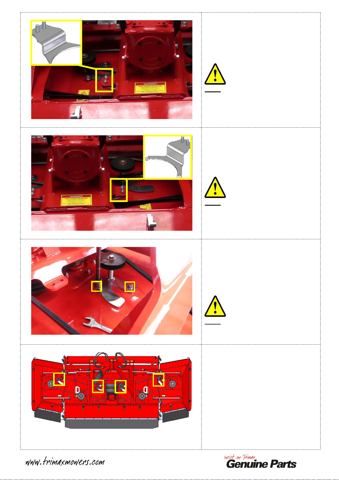
Support the weight of the Gearbox
Assembly.
Remove the Front and Rear Fasteners.
Place these to one side.
Remove the Gearbox Assembly from the
Stealth S3.
Place on a Workbench in the orientation
shown.
Note:
A support will need to placed under the
FRONT of the Gearbox Mount to
support as the assembly will become
unbalanced once the Pulley is removed!
Measure and record the distance shown
from the Pulley to the Gearbox Mount.
IMPORTANT:
This is CRITICAL, this measurement
will be used to set the Pulley back in the
CORRECT location on installation of
the replacement Gearbox.
Place support under here
Measure and
Record this
distance

4
Remove the two highlighted Grub
Screws from the Gearbox Pulley.
Re-insert one of the Grub Screws in the
hole highlighted.
Gradually tighten until the Pulley
separates from the Taper Lock Bush.
Continue to tighten this Grub Screw to
drive the Taper Lock Bush upwards.
Insert a Flat Bladed Screwdriver in the
Slot in the Biloc Bush.
Carefully lever the Bush open slightly.
Slide the Bush up and off the Gearbox
Output Shaft.
Remove the Pulley.
IMPORTANT:
Apply MINIMAL leverage while
removing the Taper Lock Bush,
otherwise cracking can occur through
the thinnest section of the Taper Lock
Bush!
Clean the Bore in the Centre of the
Pulley and the whole Taper Lock Bush
with White Spirits and a Clean Cloth
Re-assemble the Pulley as shown with
MEDIUM STRENGTH THREAD
LOCKING COMPOUND applied to
the Grub Screws.
Leave the Grub Screws loose at this
stage.
Grub screws with MEDIUM STRENGTH THREAD
LOCKING COMPOUND applied
Insert Flat Screw driver here to lever bush open slightly
Leave empty, used for pulley removal ONLY
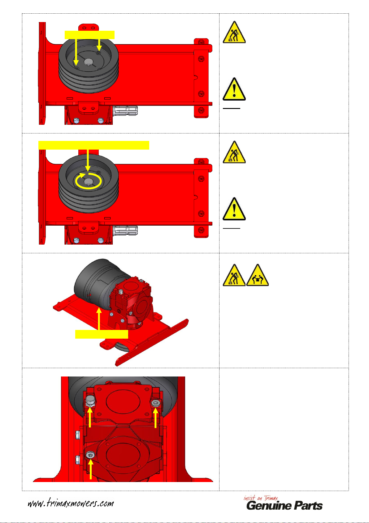
5
Support the Gearbox Mounting Plate.
Remove the fasteners and place these to
one side.
Remove the Gearbox Mount Plate from
the Gearbox.
Discard the old Gearbox.
THIS GEARBOX HAS BEEN
FILLED APPROXIMALY 1400ml
OF SAE80W90 EP GEAR OIL.
IMPORTANT:
Ensure that the oil is disposed of in
accordance with local regulations
regarding waste oil disposal!
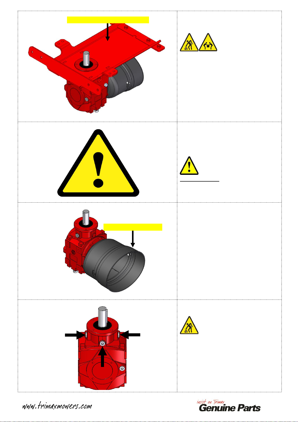
Remove the P.T.O Cone from the
Gearbox.
Place the P.T.O Cone and Fasteners to
one side.
Collect the Replacement Gearbox.
Place on the Workbench as shown.
Check that the three plugs shown are
TIGHT!
Remove the Gearbox Mount Plate
Remove the P.T.O Cone

6
Remove the Key from the OUTPUT
Shaft.
Using White Sprits and a Clean Cloth,
clean the OUTPUT Shaft and the Key.
Apply a small bead of HIGH
STRENGTH RETAINING
COMPOUND to the Keyway.
Refit the Key into the Keyway and
ensure it is fully seated.
Offer up the Gearbox Mount Plate in the
orientation shown.
Secure using the original fasteners.
One side shown.
MEDIUM STRENTH THREAD
LOCKING COMPOUND is used on
the threads of the Bolts.
Fully tighten.
Place the support back under the
Gearbox Mount Plate as before.
Using the measurement recorded earlier,
place two spacers of the required
thickness onto the Gearbox Mounting
Plate.
Note:
These will be used to set the correct
Pulley Spacing.
Align the Keyway with the Key fitted to
the OUTPUT Shaft.
Lower the Pulley onto the OUTPUT
Shaft.
Gently Drive the Pulley DOWN until it
is HARD against the Spacers
Place Spacers here
Drive Pulley onto Spacers
7
Tighten the Grub Screws to secure the
Gearbox Pulley in position.
Torque the Grub Screws to 90Nm.
Note:
An assistant may be required to hold the
assembly steady!
Gently tap around the Bush with a
Hammer.
Then re-torque to 90Nm.
Note:
This will ensure the Bush is seated
correctly in the Pulley.
Flip the Gearbox Assembly over.
Refit the P.T.O Cone using its original
fasteners.
MEDIUM STRENTH THREAD
LOCKING COMPOUND is used on
the threads of the Bolts.
Tighten to secure.
Remove the Breather, Top Plug and Fill
Level Plug from the Gearbox.
Place to one side.
Torque to 90Nm
Tap around Bush, re-torque to 90Nm
P.T.O Cone fitted

8
Pour 1400ml of SAE80W90 EP GEAR
OIL into the Gearbox through one of the
Top Holes. Oil will JUST start to seep
out from the Fill Level Hole.
Refit the Fill Level Plug and fully
tighten.
IMPORTANT:
It is CRITICAL that the correct type
and quantity of oil is used! Gearbox
failure may result from using incorrect
oil!
Refit the Top Plug and Breather as
shown.
Fully tighten.
Note:
Ensure that the Breather is in the
position shown, this prevents seepage
from the breather by placing it opposite
Gearbox rotation.
Offer up the Gearbox Assembly back to
its original position.
Secure using the original fasteners.
MEDIUM STRENTH THREAD
LOCKING COMPOUND is used on
the threads of the Bolts.
Fully tighten.
Apply a coating of Grease or Copper
Anti-seize to the Gearbox Input Shaft to
minimise corrosion.
Fill Level
Breather
Top Plug
9
Refit and tension the Belts.
Ensure these are fitted to their original
locations.
Installation is the reverse of removal.
See your Operators Manual for further
detail on the belt tensioning process.
Refit the SHORT and TALL Gearbox
Belt Retainers.
Ensure these are fitted to their original
locations. See PAGE 2 for detail.
Installation is the reverse of removal.
It is CRITICAL these are fitted to the
correct locations otherwise the Wing
Belts will not re-engage with the
Gearbox Pulley as the wings are
lowered!
VERY IMPORTANT!
•Check ALL Bolts and Nuts are
tight.
•Check ALL Belts are tensioned
correctly.
•Check Belts DO NOT foul on
ANY components.
•Ensure that no Tools or loose
parts are left behind!
Refit the Covers.
Installation is the reverse of removal.
See your Operators Manual for further
detail on the Cover fitment process.

10
Refit the P.T.O Shaft.
Installation is the reverse of removal.
See your operators Manual for further
detail on the Cover fitment process.
This process is now complete.
Other manuals for Genuine Parts Stealth S3
1
Table of contents
Other Trimax Farm Equipment manuals


Popular Farm Equipment manuals by other brands

Schaffert
Schaffert Rebounder Mounting instructions

Stocks AG
Stocks AG Fan Jet Pro Plus 65 Original Operating Manual and parts list

Cumberland
Cumberland Integra Feed-Link Installation and operation manual

BROWN
BROWN BDHP-1250 Owner's/operator's manual

Molon
Molon BCS operating instructions

Vaderstad
Vaderstad Rapid Series instructions


