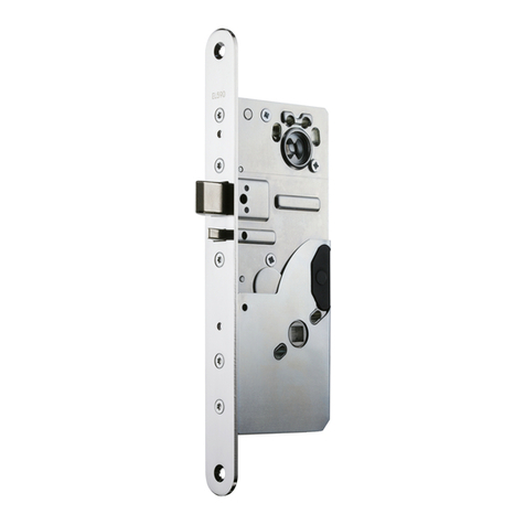
Trimec ES8000 V-LOCK User manual

IMPORTANT NOTE:
V-Lock must only be used in weather protected areas.•
V-Lock can be installed vertically or horizontally.•
For• vertical mounting, ensure V-Lock is oriented right side up as indicated by the unit label.
For• horizontal mounting, ensure V-Lock is only installed above the door.
For ideal operation, a• door gap of 3mm to 8mm is required between lock unit and strike plate.
Ensure strike plate is flush-mounted or recessed, well-supported and securely fastened to increase overall holding force and•
security of installation.
INSTALLATION INSTRUCTIONS
ES8000 V-LOCK
P
age
1
DRAWINGS NOT TO SCALE. INFORMATION IN THIS DATASHEET MAY BE CHANGED WITHOUT NOTICE.
P
age
4
SPECIFICATIONS
An ASSA ABLOY Group brand
DA0076, Issue 8: 13 May 2008
LOCK MODE CONFIGURATION
STEP 3
- Change jumper position on Printed
Circuit Board beneath the red
re-sealable sticker as shown below:
Power-to-Open
(Fail Secure)
Power-to-Lock
(Fail Safe)
STEP 2
- Rotate Latch Plate screw beneath
the red re-sealable sticker according to
orientation shown below:
Turn counter-clockwise
180ofor Power-to-Open
(Fail Secure)
Turn clockwise 180ofor
Power-to-Lock (Fail Safe)
STEP 1
- Loosen both screws on side of lock
body.
- Slide screws in direction required until
stop at end of slot is reached.
- Hold in position and re-tighten screws.
PTL
PTO
If the lock had been installed or previously operated, the latch plate screw (STEP 3) may not be visible. To•
change lock mode configuration, contact your distributor for additional instructions.
Ensure all re-sealable stickers and screws are re-attached after configuration to prevent ingress of dust.•
5 Year Limited Warranty
ASSA ABLOY Australia guarantees for a period of 5 years in accordance with Trimec’s Standard Warranty Conditions, against defects in
manufacture, workmanship or materials, provided that all electrical and mechanical installation requirements are adhered to as per this
datasheet. All third party and consequential claims are expressly excluded from this warranty.
warranty ASSA ABLOY Australia
2/16 Atkinson Road
Taren Point 2229
NSW, Australia
www.assaabloyasiapacific.com
Parameter Specification
Door Gap Between 3mm to 8mm only
Lock Monitor Output Voltage free changeover switch contacts rated for 48vDC / 100mA
Holding Force AS4145.2 - 1993: Passed S3 (611kg for 1 minute)
Capable of 1000kg if strike plate is fully supported
Release under Side Load 15kg max at bolt with motorised unlocking (3 wire control)
3kg max at bolt with Power-To-Lock (Fail Safe) unlocking and 2 wire control
Bolt Dimensions Diameter = 11mm
Projection = 20.5mm
Power Supply (12-28VDC) Regulation better than +/- 2%
1Amp Power supply required
Current Draw Power to Lock holding current 130mA
Power to Open holding current 30mA
Initial locking and unlocking current draw higher
Misalignment tolerance +/- 3.5mm
Operating Temperature -10oC to +50oC at 90% RH
Durability > 300,000 cycles
Certifications 2-hour fire rating
WITH 30MM FACEPLATE

Page
2
P
age
3
Mark LINE 1 corresponding to mid-plane of door (see1. Fig. 1).
On door jamb, mark LINE 2 which will be in line with LINE 1 (see2. Fig. 2).
Mark cutout of V-Lock symmetrically about LINE 2. Cutout size must be 256mm x 30mm. Thickness of strike plate and lock3.
faceplate are 3mm each. Prepare door jamb appropriately as shown in Fig. 2.
Ensure all wiring is correctly connected and not rubbing on sharp edges or interfering with any lock mechanism.4.
Install lock unit into door jamb as shown in5. Fig. 3.
On the door, mark LINE 3 corresponding to the top edge of lock faceplate (see6. Fig. 1). Mark and recess cutout of strike plate
on door symetrically about LINE 1, and using LINE 3 as reference.
Install strike plate on door, and ensure that door gap between strike plate and lock faceplate is between 3mm and 8mm7.
only (see Fig. 3).
Power up lock, then let door open and close normally with door closer. When strike plate magnet comes within locking range,8.
the V-Lock unit will lock as long as lock bolt closes within target locking range (see Detail A).
Fig. 1 - Door Preparation
For locking bolt on V-Lock unit to attempt locking, strike plate magnet MUST be correctly aligned and in•
front of the M mark on the lock faceplate. Lock will not operate without strike plate.
Fig. 2 - Door Jamb Preparation
Detail A - Target Locking Range
If door closes outside target locking range (+/- 3.5mm), V-Lock will execute 5 locking•
attempts.
If lock bolt cannot enter the strike hole after 5 attempts, lock will cease• operation to
prevent motor burn-out.
When this happens, adjust door closer or re-position strike plate. To restart• locking
sequence, send another door open/close signal to the V-Lock.
Fig. 3 - V-Lock Installation
ELECTRICAL SPECIFICATIONS
The V-Lock is designed to be controlled with a minimum of 3 wires. Positive voltage should be connected to the
RED wire providing permanent power, a second negative wire connected to BLACK and a third positive voltage
wire connected to BLUE providing a lock/unlock signal. When connected with 3 wires the motor will provide
power assisted unlocking allowing the bolt to retract with up to 15kg of side load. Voltage-free changeover
switch contacts are provided for bolt position monitoring. When locked, the monitor switch (COM - PURPLE) is
connected to (NC - ORANGE).
The V-Lock is multi-voltage and operates with either 12 to 24vDC power. It has in-built Reverse Polarity Protection
for installer safety. For a lock in locked position, wiring diagrams for both Power-To-Open (Fail Secure) and Power-
To-Lock (Fail Safe) are found below:
Bolt Position
Monitor
Power To Lock (PTL) Wiring Connections
- Access Control (PTL)
ORANGE
BLACK
BLUE
RED
PURPLE
WHITE
- 0 volts d.c.
- Positive Continuous Supply
- (COM)
- (NO)
- (NC)
-
+
DC Power
NC
NO
Bolt Position
Monitor
Power To Open (PTO) Wiring Connections
ORANGE
BLACK
BLUE
RED
PURPLE
WHITE
- 0 volts d.c.
- Access Control (PTO)
- Positive Continuous Supply
- (COM)
- (NO)
- (NC)
NC
NO
-
+
DC Power
In Power-To-Lock (Fail Safe) configuration, it is possible to operate the V-Lock using 2 control wires only. With 2 wire control
the lock relies on the Fail Safe spring mechanism to unlock, which reduces the lock’s capability to open under side load to only
3kg. Hence, 2 wire control is NOT RECOMMENDED and should be avoided wherever possible.
For retrofit applications where only 2 control wires may exist, connect the BLUE and RED wires on the lock together and join
them to the positive supply voltage. Connect the negative supply voltage to the BLACK wire on the lock (see below).
Bolt Position
Monitor
Power To Lock 2 Wire Control - NOT RECOMMENDED
ORANGE
BLACK
BLUE
RED
PURPLE
WHITE
- 0 volts d.c.
- (COM)
- (NO)
- (NC)
-
+DC Power
256
Strike Plate
3mm Thickness
7
48
242
24132
D22 x 20 Deep
27
Door
LINE 3
LINE 1
(Half thickness of door)
M
Lock
Faceplate
256 1515
30
30
256
50
24
42
210
Door Jamb
LINE 2
Magnet
Maximum door gap
3mm - 8mm
Strike Plate
V-Lock Unit Door Jamb
Door
M
Mounting Tabs (supplied)
Required for Flush Mounting only
Magnet and M must line
up for V-Lock to operate
3.5mm
3.5mm
INSTALLATION
Other Trimec Lock manuals
