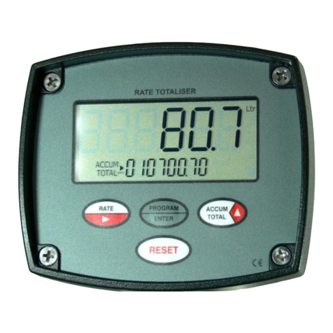
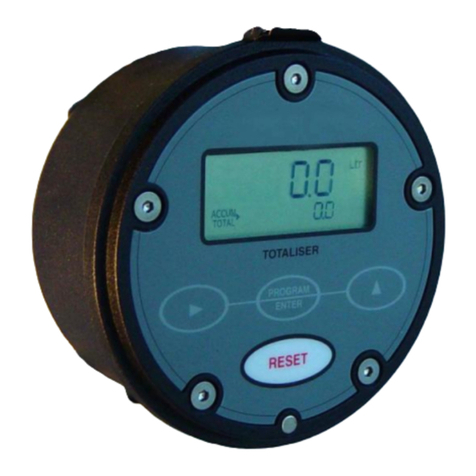
Trimec rt11 User manual

TRIMEC INDUSTRIES Pty.Ltd.
1 / 19 Northumberland Road, Caringbah
( PO Box 2444 Taren Point )
Sydney 2229, NSW - AUSTRALIA
Tel : +61 2 9540 4433
Fax: +61 2 9525 9411
Website: www.trimecind.com
TRIMEC Europe Ltd
Floor 3, 5A Boltro Road
Haywards Heath West Sussex,
UNITED KINGDOM RH16 1BP
Tel : +44 144-441-7880
Fax : +44 144-441-7668
Website : www.trimecind.com
IMRTVDC-1105
I N S T R U C T I O N M A N U A L
RT FLOW RATE TOTALISER
Distributed by:
Universal Mount Series

20
Dual flow inputs :
The model RT12 has a dual flow input feature which can be configured for one of three
available functions of A+B, A-B or A÷B (ratio).
The dual flow inputs are referred to as “input A” and ”input B” at terminals 1 & 3.
Function A+B
Both inputs are added together and displayed as one for Rate, Resettable & Accumulative
Totals.
Displays Rate : The total of A+B flow rates displayed as one rate.
Reset Total : The total of A+B totals displayed as one total.
Accum. Total : The total of A+B accum.totals displayed as one total.
Outputs Scaled Pulse : Scaled pulse value is relative to the totalised values.
Alarms : Alarms are taken relative to the displayed rate.
Analog Output : 4~20mA output is proportional to the displayed rate.
Function A-B
Input B is subtracted from input A, the resultant is displayed as one for Rate, Resettable &
Accumulative Totals.
Displays Rate : The difference of A-B flow rates displayed as one rate
Reset Total : The difference of A-B totals displayed as one total.
Accum. Total : The difference of A-B accum.tot. displayed as one total.
Outputs Scaled Pulse : Scaled pulse value is relative to the totalised values.
Alarms : Alarms are taken relative to the displayed rate.
Analog Output : 4~20mA output is proportional to the displayed rate.
Function A÷B
Input A is divided by input B, the resultant is displayed as an instantaneous Ratio, Resettable
& Accumulative Totals are independently displayed for both A & B inputs.
Displays Rate : The resultant Ratio between A÷B flow rates
displayed as an instantaneous Ratio.
Reset Total input A : The total of input A.
Reset Total input B : The total of input B.
Accum. Total input A : The Accumulative total of input A.
Accum. Total input B : The Accumulative total of input B.
Outputs Scaled Pulse : The scaled pulse output relates to input A .
* Alarms : Alarms are taken relative to the displayed ratio.
* Analog Output : 4~20mA output is proportional to the displayed ratio.
* Note: The alarm and analog outputs for the A÷B function are set in the initial stages of
programming in relation to rate units eg: setting the analog output range to 4mA = 00.000
litres/min and 20mA = 10.000 litres/min, the analog output will be proportional to the ratio rate
display of 0.000~10.000 ( eg. 4mA @ 0.000 and 20mA @ 10.000 ).
The same set up analogy applies to the alarm settings.
Page 1
TABLE OF CONTENTS
1. INTRODUCTION
1.1 Model number designation 2
1.2 Specifications 3
1.3 Overview 4
1.4 LCD displays 4
2. OPERATION
2.1 Accumulative total display 5
2.2 Resettable total display 5
2.3 Rate display 5
2.4 Low frequency cut-off 5
2.5 Inhibit total function 5
2.6 Keypad function matrix 6
3. INSTALLATION
3.1 Mounting - wall / surface mount 6
- pipe mount 7
- panel mount 7
3.2 Flowmeter connections - unpowered sensors 8
- powered sensors 9
3.3 Wiring connections - external powering 10
- 4~20mA loop powering 10
- wiring requirements 10
- pulse outputs 11
- alarm outputs 11
- remote switches (refer page) 18
4. PROGRAM PARAMETERS ( models RT11& RT12 )
4.1 PIN number program protection 12
4.2 Resetting accumulative total 12
4.3 Engineering units 12
4.4 K-factor (scale factor) 12
4.5 Rate conversion factor 12
4.6 Rate dampening ( see response graph page 19 ) 12 & 19
4.7 Low frequency cut-off ( refer clause 2.4 page 5 ) 5
4.8 Pulse outputs ( scaleable or non-scaleable ) 12
4.9 Non linearity correction ( NLC) Linearisation 12
4.10 Presetting battery power levels 13
5. ADDITIONAL PROGRAM PARAMETERS ( model RT12 only )
5.1 Analog output 13
5.2 Flow alarms 13
5.3 Flow alarm deadband 13
5.4 Dual flow inputs 13 & 20
6. PROGRAMMING FLOW CHART
6.1 Model RT11& RT12 program levels 1~7 14
Model RT11& RT12 program levels 8~13 15
6.2 Model RT12 program levels 14~24 16
6.3 Program detail record 17
7. TERMINAL LAYOUT, SELECTION LINKS & REMOTE SWITCHES 18
8. ALPHABETICAL INDEX 21

2 Introduction
19
Rate dampening :
Rate dampening value verses time to reach new reading ( for an instantaneous change in
actual flow rate )
1.1 Model number designation
Model
Function
( all instruments have program PIN protection )
RT11 Rate totaliser, battery or DC powered with pulse outputs, 10 point NLC
RT12 RT11 rate totaliser with 4~20mA & alarm outputs, dual flow inputs
Electrical access
1
3 x M20 x 1.5mm female t hreaded conduit entry ports w ith knock-outs
23 x 1/2" NPT female threaded conduit entry port s w ith knock-outs
Flow input type
DDigital ( pulse or f requency )
Analog
( 4~ 20mA )
Power supply
0Self powered ( battery ) or regulated 8~24Vdc
Housing type
FM Universal field mount ( can be panel mounted )
MM Integral meter mount
Options
i
Intrinsically safe t o Exia IIB T6
( refer factory )
m o d e l No. e x a m p l e
RT12 1 D 0 FM i
Accessories
AWM stainless steel wall mount kit ( see page 7 )
APM stainless steel 2" pipe mount kit ( see page 7 )
ACF MP series cooling fin kit for flowmeters with integral registers
ADM DP & turbine stem adaptor - metric ( M16 to M20 )
ADN DP & turbine stem adaptor - USA ( M16 to 1/2" NPT )
ASS DP490 stem ( 100mm effective height, threaded M16 male )
ASL DP525 stem ( 350mm effective height, threaded M16 male )
ATM * universal stem for Turbine meters ( 3/4" BSPF to M16 )
AUS * universal swivel stem for Turbine meters ( 1" NPTF to M16 )
0
5
10
15
20
25
30
35
40
45
50
5 10 15 20 25 30 35 40 45 50 55 60 65 70 75 80 85 90 95
RT DAMPENING VALUE
RESPONSE TIME (seconds)
Responce curve
to 90% of actual
flow rate
Responce curve
to 99% of actual
flow rate

18
7. TERMINAL DESIGNATION
Terminal layout - links & remote switch inputs
Introduction 3
1.2 Specifications
Display : 8 digit alpha numeric LCD characters 9mm ( 0.35 ”) high with
second line sub script text, 8 digits totalising, 5 digits rate,
3 programmable decimal points with all displays.
Signal Input : Universal pulse/frequency input compatible with Reed switch,
Hall effect, Namur proximity detectors, Pulse wire, optical &
Coil~sine (15mV P-P min). Maximum input frequency 10Khz.
Minimum input frequency for rate display is 0.1hz with low
frequency cut off feature enabled, 0.3hz when disabled & 0.7hz
if the non-linearity feature is enabled. Totals have no mimimum.
Battery power : Battery life expectancy can be up to 5~10 years when
(reverse polarity protected) programmed with the unique “Ultra Power Save” sleep cycle.
Battery life reduces when connected with a coil input from turbine
flowmeters. Rate display defaults to total display 4 minutes after
pressing the rate key in order to conserve battery power.
External power : Regulated 8~24Vdc x 150mA or 4~20mA loop powered. Rate or
total display will remain visible at all times when selected.
Pulse output : NPN-PNP transistor, scaleable or non-scaleable, 1A max.
Analog output : Two wire loop powered, 12~28Vdc into 100~900Ωloop load,
accuracy +/-0.1% FS, key entry programming of Zero & Span.
Alarm outputs : Two NPN-PNP selectable FET (transistors) programmable low &
high flow alarms with adjustable deadband (reset differential).
Maximum drive 100mA resistive load. 24Vdc max.
Physical : A) IP66 (NEMA 4X) high impact glass reinforced nylon enclosure.
B) 3 x M20 or ½” NPT female conduit entries.
C) 122mm diameter x 61mm deep x 400g (0.9lb).
D) Temperature range from -20ºC to +80ºC ( -4ºF to +176ºF).
Configuration : Flow chart data entry with scrolling English text prompts. 4 digit
PIN number set-up protection. Programmable rate units & time
base for rate, rate dampening, decimal points & low freq. cut-off.
K-factor range : Eg. Pulses/litre, gallon, lb etc. Programmable range is 0.001~
9999999.999 with a floating decimal point during K-factor entry.
Engineering units : Selectable Ltr, gal, m3, kgs, lbs (total). /sec,min,hr or day (rate).
Rate conversion : Enables the rate to be displayed in different engineering units to
that of the totals eg: totals in barrels (oil) & rate in US gallons.
Battery modes : Ultra power save, standby or continuous display selectable.
Dual Inputs option : Programmable for computations of A+B, A-B, or A÷B (ratio).
LINKS 13 & 14
select NPN or PNP
style alarm outputs
13
PNP
NPN
14
SER.
ON
1 2 3
A
ON
1 2 3
B
7A
1
2
3
4
5
6
7
14
13
12
11
10
9
8
Inhibit total
switch
( clause 2.5 )
REP (repeater pulse)
SPO (scaled pulse)
0 0 0
PNP
NPN
7B
LINK 7B
Select NPN or PNP
style pulse output
LINK 7A
select SPO or REP pulse
output ( see clause 4.8 )
SWITCH 1 :
ON engages 0.01µf capacitor to
suppress reed switch bounce
SWITCH
2 :
ON engages 1 meg Ωpull up resister
SWITCH 3 :
ON engages 820
Ω
pull down resister
0
0
0
REMOTE KEYS
reset
rate / total
program
accum. total
use momentary
action switches
0
0
0
battery
Flow input
conditioning DIP
switches
Terminals 1, 2 & 5 replicate
terminals 3, 4 & 5 for dual
flow inputs
Terminal
-0V (ground) 8
not used 9
not used 10
-4~20mA output 11
+4~20mA output 12
Low flow alarm 13
High flow alarm 14
Terminal
2
3
4
6 +8~24Vdc in
7 Pulse output
5 -0V (ground)
Flow
input B
Flow
input A
1

4 Introduction
1.3 Overview
The RT series instruments are specifically designed for computing, displaying and
transmitting totals and flowrate from flowmeters with pulse or frequency outputs.
The instrument will display Flow Rate, Resettable Total and an Accumulated Total in
engineering units as programmed by the user. Simple flow chart programming with scrolling
English prompts guide you through the programming routine greatly reducing the need to
refer to the instruction manual. All user program data is retained if the battery is removed.
Special Features
Standard : 10 point Linearisation, PIN Protection, NPN/PNP selectable autoranging pulse
outputs (scaled or un-scaled), Low frequency cut-off, Battery conservation mode.
Optional : 4~20mA output, High / Low flow alarms with adjustable deadbands, Dual inputs.
Environments
The RT is weatherproof to IP66 (Nema 4X) standards, UV resistant glass reinforced nylon
with stainless screws & viton O-ring seals.The instrument suits harsh indoor and outdoor
environments & conforms to EMC directive 89/336/EEC Electro Magnetic Compatibility.
Conforming standards include: EN 61326 ( immunity in industrial locations )
EN 62326 ( emissions in industrial locations )
EN 60529 ( degrees of protection [ IP ] )
Installation
Specifically engineered to be directly mounted on a variety of flowmeters, wall or surface
mounted, pipe or panel mounted. Various mounting kits are available. The instrument can be
self powered or may be powered by an external dc supply or two wire loop powered.
1.4 LCD displays
Programming 17
6.4 Program detail record
Your back up 4 digit PIN number is 1820
To remember consider the model No. RT - “R” is the 18th & “T” the 20th letter of the alphabet.
Pencil your program details here
K =
Units / Sec Min Hr Day
L7
User selected PIN No.
K-factor (scale factor)
Engineering units
Time base for Rate
L1
L4
L3
RCF=yes no
Rate conversion factor
L6
L8
Rate dampening
Decimal for Accum. total
Decimal for Rate
Decimal for reset Total
L5
4mA @
20mA @
@
%
@
%
yes no
yes no
yes no
A+B A-B A
÷
B
K =
L14
L17
Alarm outputs
L15
L16
L20
L21
L18
L19
-
high deadband
-
low set point
-
low deadband
-
high set point
Analog output
-
zero set point
-
span set point
Dual flow inputs
-
K
-
factor
for B input
-
dual input function
L22
L23
L24
Ultra save Standby Continuous
L13
Power mode
3F Hz
K-factor =
4F Hz
K-factor =
5F Hz
K-factor =
6F Hz
K-factor =
7F Hz
K-factor =
8F Hz
K-factor =
9F Hz
K-factor =
2F Hz
K-factor =
1F Hz
K-factor =
0F Hz
K-factor =
yes no
L12
Non linear correction
-
frequency 0
-
frequency 1
-
frequency 2
-
frequency 3
-
frequency 4
-
frequency 5
-
frequency 6
-
frequency 7
-
frequency 8
-
fre
quency 9
percentage
percentage
0 0.0 0.00 0.000
0 0.0 0.00 0.000
0 0.0 0.00 0.000
L11 pulse value =yes no
Pulse output
Hertz =L9
Low frequency cut
-
off
L10
Full LCD display test feature illuminates all
display segments and script text displays for 5
seconds when entering the program mode.
Ltr
gal
m3
lbs
kgs
RUN ACCUM. TOTAL STOP BAT LOW HIGH RATE
The 8 digit Accumulative Total
display can be
programmed for up to 3 decimal places. Reset
is only possible when in the program mode
which can be PIN protected for security.
gal
ACCUM. TOTAL
Rate
display has flashing SEC, MIN, HR or DAY
followed by up to 5 digits of rate programmable
for up to 3 “floating” decimal places.
Ltr
RATE
The 8 digit Total display is push button or
remote resettable and can be programmed for
up to 3 decimal places.
TOTAL
lbs

16 programming
6.2 Program levels 14~24 ( Model RT12 only )
Operation 5
2. OPERATION
2.1 Accumulative Total
Accumulative total can be reset at L2 in the program mode. The accumulative total can be
displayed momentarily or continuously through use of the front panel ACCUM TOTAL key.
Momentary display : Accumulative total is displayed only whilst the key is held pressed.
Latching display : To have the accum. total display latch when key is pressed simply
press & hold the ACCUM TOTAL key for 10 seconds, the display will then latch each time the
key is pressed. Holding the accumulative total key again for 10 seconds will revert this key
function back to a momentary action.
2.2 Resettable Total ( also see page 18 for remote reset feature )
The display toggles between Rate & Total when the RATE-TOTAL key is pressed.
Pressing the RESET key whilst displaying total will cause the total to reset to zero.
2.3 Rate display
When rate is displayed the leading three alpha characters on the left of the display “flash ”
the time base for rate eg. rate /SEC. rate /MIN. rate /HR. or rate /DAY. Decimal points float
to provide good resolution & rangeability.
The minimum input frequency for rate display is 0.3hz reducing to 0.1hz If the low frequency
cut-off is set to 0.1Hz (see below).
2.4 Low frequency cut-off
The low frequency cut-off is most commonly set to 0.0Hz (disabled) other than to:
1) To display rate for input frequencies below 0.3hz, for example setting the cut-off at 0.1Hz
the rate will continue to display for input frequencies as low as 0.1Hz (one pulse every 10
seconds), such conditions often apply to flowmeters with low resolution pulse outputs (low
frequency) or flowmeters with a high operational turndown (maximum to minimum flow rate).
2) Inhibit the integration & registration of “apparent flow” which at times may be encountered
on mobile installations where the movement of the vehicle or dead heading a pulsating pump
may cause spurious flow signals which are not attributed to actual flow.
3) Inhibit the integration & registration of flow at input frequencies below what is considered
the minimum accurate flow rate of the primary flow element (flowmeter).
Caution: If the low frequency cut-off is set to any value other than 0.0Hz then the integration
of rate and total will cease at frequencies on or below the set value (HERTZ).
2.5 Inhibit total (see wiring schematic page 18)
With the remote “inhibit total” switch closed the RT with display flow rate but at the same time
will inhibit the resettable & accumulative totalising functions.
1)
Low
flow alarm
occurs when the flow falls
below the set point, High flow alarm occurs
when the flow goes above the set point.
2) Deadband (Reset Differential), provides a
buffer zone about the alarm set point in order
to avoid alarm output “chattering ” on & off
when the flow rate is hovering about an alarm
set point.
The % deadband applies above the Low set
point and below the High set point. Deadband
is set as a percentage of each set point.
Eg: 5% deadband at a low alarm set point of
100 L/hr will cause a low alarm when the
flow drops to 100 L/hr, the alarm will not
switch off until the flow increases above
105 L/hr.
Alarm outputs
YES
L14 ANALOG OUTPUT REQUIRED Y / N
4 ~ 20mA Y - N
L15 ENTER FLOW RATE AT 4mA
XXXXX.XXX
LOW
L16 ENTER FLOW RATE AT 20mA
XXXXX.XXX
HIGH
program return
YES
L17 ALARM OUTPUTS REQUIRED Y / N
ALARMS Y - N
L24 SET DUAL INPUT FUNCTION
A + B A - B A
÷
B
L23
ENTER NUMBER PULSES PER
Ltr m3 kg gal lb (unit) FOR INPUT B
00000.001 - 9999999.9
L22 DUAL INPUTS REQUIRED Y / N
DUAL Y - N
L18 ENTER FLOW RATE LOW ALARM
XXXXX.XXX
LOW
L20 ENTER FLOW RATE HIGH ALARM
XXXXX.XXX
HIGH
L19 ENTER LOW ALARM DEADBAND %
BAND XX %
LOW
L21 ENTER HIGH ALARM DEADBAND %
BAND
XX
%
HIGH
YES
NO
NO
NO
TIP:
holding the prog. key for 3 se
c’s
quick tracks to the END of the program
PROG
Ltr / SEC
( litres / second )
Ltr
RATE

6 Operation
2.6 Keypad function matrix
3. INSTALLATION
3.1 Mounting
Programming 15
6.1 Program levels 8 ~ 13 (RT11 & 12)
KEY FUNCTION IN OPERATING MODE FUNCTION IN PROGRAM MODE
Toggles between Rate & Total displays.
Resets the Total display to zero
only when Total is being displayed.
No function
No function
1) Pressing the Prog. & Rate/Total keys for 5
seconds enters you into the program mode.
2) Displays model & software revision No.
1) Each press steps you through each
level of the program chart.
2) Holding for 3 seconds fast tracks to the end
of the program from any program level.
No function
Selects the digit to be set, the selected digit
will be “flashing ” indicating that it can be
incremented.
No function
Increments the selected digit each time
that it is pressed.
Displays Accumulative Total when pressed.
( refer clause 2.1 for options )
No function
ACCUM
TOTAL
RATE
TOTAL
RESET
PROGRAM
ENTER
L8 SET RATE DAMPENING
DAMP 00 ~ 99 RATE
program returns to end or advances
to next level if model RT12
1)
Any number up to 10 frequency points of non
-
linearity can be programmed with point 0F being
the pulse output frequency at the lowest flow rate.
2) If any frequency point is set to zero Hz then
all remaining NLC points up to point 9F will
automatically assume the last entered NLC
K-factor and the program will advance to the
next level. This feature simplifies programming
when not all points of correction are used.
3)
Linear interpolation is used between frequency
points, except above the last entered frequency
where the last entered NLC K-factor is applied.
Non-linear correction (NLC)
( overrides K-factor set at L4 )
1) ULTRA POWER SAVE
2) STANDBY
3) CONTINUOUS
( refer clause 4.10 )
YES
continued if
model RT12
NO
YES
9F 0000.0 (set output freq. at point 9)
000000.000 ( set K-factor at point 9 )
10 points from 0F up to 9F
L12 NON LINEAR CORRECTION
NLC Y - N
0F 0000.0 (set output freq. at point 0)
000000.000 ( set K-factor at point 0 )
1F 0000.0 (set output freq. at point 1)
000000.000 ( set K-factor at point 1 )
YES
L10 OUTPUT PULSE REQUIRED Y / N
PULSE Y - N
NO
L11
ENTER No. OF gal - litres etc
PER OUTPUT PULSE
OP XXXX . X
NO
Low frequency cut-off
The low frequency cut-off is generally set to
0.0Hz (disabled) for most applications other
than those described at clause 2.4 on page 5
L13 CHANGE POWER MODE Y / N
CHANGE Y - N (applicable under battery only)
HERTZ 0.0 ~ 9.9
L9 SET LOW FREQUENCY CUT-OFF
program return
Surface mount footprint
(use 4 screws supplied )
Wall mount using optional
bracket set ( P/No. AWM ) 18 mm
( 0.7 ” )
80 mm ( 3.15 ” )
42.6 mm
( 1.67 ” )
RATE
TOTALISER
RATE
TOTAL
ACCUM
TOTAL
PROGRAM
ENTER
gal
RUN ACCUM. TOTAL
STOP BAT LOW HIGH
RESET

14 Programming
6. PROGRAMMING FLOW CHART
6.1 Program levels 1~7 (RT11 & 12)
Installation 7
3.1 Mounting (continued)
press Prog. key
to step through
program levels
PROG
continued
program return
if PIN protected
L3 SET ENGINEERING UNITS
ENG UNIT Ltr gal m3 Ibs kgs (none)
L2 RESET ACCUM TOTAL Y / N
RESET Y - N
L5 SET DECIMAL POINTS
DPt TOTAL 0 0.0 0.00 0.000
DPt ACCUM TOTAL 0 0.0 0.00 0.000
DPt RATE 0 0.0 0.00 0.000
L1 CHANGE PIN No. Y / N
NU PIN Y - N
PIN * * * *
YES
NO
L4
ENTER NUMBER PULSES PER
Ltr m3 kg gal Ib (unit of measure)
0000000.001 ~ 9999999.999
Saves & exits program
YES
L7 SET TIME BASE FOR RATE
Ltr gal etc / SEC MIN HR or DAY
L6 RATE CONVERSION Y / N
RATECON Y - N
NO
RT11 V3.0 HOLD 3 2 1
PROGRAM MODE ENTERED
TESTING DISPLAY 88888888
INVALID PIN VIEW
EXISTING PROGRAM
DETAILS ONLY
if incorrect
PIN No. is entered
K
-
factor
(scale factor)
is the number of
pulses per unit volume or unit mass
eg: 20.465 pulses / litre, gallon, kg etc.
R 0000.001 ~ 9999.999
WARNING
on rate con
version factor (RCF)
This feature need only be programmed when
the total & rate engineering units are to be
different. eg: m3 for total and litres for rate
The conversion factor is the number needed
to convert to the required rate unit, some
examples are:
Total unit
Rate unit
Conversion factor
Cubic metres
US Barrels
Imp. gallons
1000.000
42.000
4.546
Litres /
USgal /
Litres /
PROG
RATE
END
Y - N
NO
YES
hold Program & Rate
keys for 5 secs to
enter the program
PIN
* * * *
ENTER PIN
* order Pipe mount kit P/No. APM
comprising two brackets,
screws and worm drive clamps.
Conduit entries have an integral
moulded seal, to remove break
seal out using suitable lever
( eg. screwdriver or rod )
* Horizontal
pipe mount
* Vertical pipe mount
RATE
TOTALISER
RATE
TOTAL
ACCUM
TOTAL
PROGRAM
ENTER
gal
RUN ACC
UM. TOTAL
STOP BAT LOW HIGH
RESET
Panel mount
Cut a 106.5mm (4.2 ”)
diameter hole in panel

8 Installation
3.2 Flowmeter connections ( unpowered sensors )
Programming 13
4.10 Presetting battery power levels
When the instrument is operated under battery power only a special “Power Mode” program
option will appear at level 13 within the programming routine. A choice of three battery power
modes enable maximisation of the battery life according to operational requirements:
Ultra Power Save: Typically selected if reading the register infrequently. The display scrolls a
Prompt “PRESS ANY KEY”, when a key is pressed display wakes up for
4 minutes then returns to sleep mode* greatly extending the battery life.
Standby : Display becomes active whenever a key is pressed or product flows
through the flowmeter. Display returns to sleep mode* after 4 minutes of
no flow input or key actions, prompt then returns to “PRESS ANY KEY”.
Continuous: Display is active at all times resulting in reduced battery life. Display
reverts from Rate to Total after 4 minutes to reduce battery draw.
* In sleep mode (and programming mode) flow is always continually totalised.
5. ADDITIONAL PROGRAM PARAMETERS ( model RT12 )
5.1 Analog Output
The loop powered 4~20mA output can be spanned anywhere within the flow meter range.
Testing the current loop is available during programming when 4mA will output at
programming level L15 and 20mA will output at level L16 (page 16).
5.2 Flow Alarms
Two flow alarm FET (transistor) outputs may be programmed for Low & High flow alarms.
5.3 Flow Alarm Deadband
Alarms are NPN/PNP link selectable. An adjustable deadband (reset differential) provides
a trip buffer zone about the set point in order to overcome alarm “chattering” when the flow
rate is fluctuating close to the alarm set point.
Deadband is entered as % of each set point value (refer to page 16 for an example).
5.4 Dual Flow Inputs (see also page 20 for a fuller description)
When externally powered the RT12 accepts inputs from two flowmeters (input A& input B),
a separate scaling factor is entered for the second flow input, the instrument is then
programmed for one of the dual input functions of A+B, A-B or A÷B (ratio).
A+B Both inputs are added and displayed as one for Rate & Totals.
A-B Input B is subtracted from input A & the difference is displayed for both Rate & Totals.
A÷B Totalises A & B separately & Rate is a function of A÷B to give instantaneous ratio.
Note : - When using A & B inputs the functions of Scaled Pulse output, Alarm set points
and the Analog output are relevant to resultant computation between A & B.
- The analog output of function A÷B can be used as an input for ratio control.
1. Reed switch ( 200hz max.)
DIP
switch 1
(debounce)
&
Switch 2 (pull up) are on
6
5
4
3
2
1
7
+8~24Vdc in
Pulse output
-0V (ground)
Flow
Input A
-4~20mA output
-
0V (ground)
not used
+4~20mA output
Low flow alarm
8
9
10
11
12
13
14
High flow alarm
not used
Flow
Input B
3
2
1
O
N
3
2
1
O
N
Ground screen at -0V (5)
3. Coil ( Turbine & paddle style flowmeters )
All DIP switches off (position switch 1
ON if unit is effected by line noise)
use twisted pairs
6
5
4
3
2
1
7
+8~24Vdc in
Pulse output
-0V (ground)
Flow
Input A
-4~20mA output
-
0V (ground)
n
ot used
+4~20mA output
Low flow alarm
8
9
10
11
12
13
14
High flow alarm
not used
Flow
Input B
3
2
1
O
N
3
2
1
O
N
2. Pulse wire
All
DIP swit
hes off
S
N
0.1 ~ 2 vdc
6
5
4
3
2
1
7
+8~24Vdc in
Pulse output
-0V (ground)
Flow
Input A
-4~20mA output
-
0V (ground)
not used
+4~20mA output
Low flow alarm
8
9
10
11
12
13
14
High flow alarm
not used
Flow
Input B
3
2
1
O
N
3
2
1
O
N
Ground screen at
-
0V (5)
Switch 1 : ON engages 0.01µf capacitor to suppress reed switch bounce
Switch 2 : ON engages 1 meg Ωpull up resister
Switch 3 :
ON engages 820
Ω
pull down resister
3
2
1
O
N
Flow input A & B switch functions
Terminals 1, 2 & 5 replicate terminals 3, 4 & 5 for dual flow inputs
3
2
1
O
N
A
B Switch 1 : ON engages 0.01µf capacitor to suppress reed switch bounce

12 Programming
4. PROGRAM PARAMETERS ( models RT11 & 12 )
4.1 PIN No. Program Protection
Any user defined PIN number other than 0000 will engage the program protection feature,
failure to input the correct PIN number will deny the ability to change any of the program
parameters but will allow the user to step through and view the existing program parameters.
Only one PIN number may be set but this can be changed at any time after gaining access
through PIN entry. A second back up PIN number is installed at the factory should the
programmed PIN be lost or forgotten. ( refer bottom of page 17 for the back up PIN No. )
4.2 Resetting Accumulated Total
Resetting the accumulated total can only be done at level 2 (L2) in the program mode.
4.3 Engineering Units ( refer clause 1.4 )
Select from available Engineering units to right of the display. No eng. units denote NIL set.
4.4 K-factor (scale factor)
Enter K-factor starting with the most significant number, up to 7 whole numbers & 3 decimal
numbers can be entered. Trailing decimal numbers move into view as digits to the right are
progressively selected, any significant digits which may move from view remain functional.
4.5 Rate conversion factor
A rate conversion feature is available & is explained at level 6 in the program chart (page 14).
4.6 Rate dampening
Dampening is available to smooth out fluctuating flow input signals in order to provide a
stable rate display & analog output. Most input signal are reasonably stable and need only a
low setting value of 40 to 70 ( see response graph on page 19 ).
4.7 Low frequency cut-off This feature is explained in clause 2.4 ( page 5 ).
4.8 Pulse Outputs ( Instrument must be externally powered as per page 10 )
The pulse output is link selectable as a scaleable pulse or non-scaled repeater pulse & NPN
(current sinking) or PNP (current sourcing) style pulse capable of switching up to 1 amp.
Pulse scaling, when selected, is set as the number of litres / gallons etc. per output pulse
Eg. 0.1 litres/pulse, 10 litres/pulse, 100 gallons/pulse. Range is 0.1 - 9999.9 Eng.unit/pulse.
The pulse width (pulse duration 1:1) automatically adjusts to the output frequency defaulting
to a maximum pulse width of 300 milliseconds at frequencies below 1.66hz. To calculate
pulse width at higher frequencies use: 1000 ÷(hz x 2) = pulse width in milliseconds.
4.9 Non Linearity Correction ( NLC ) - Linearisation
Linearisation enables the instrument to correct for known inaccuracies in a flowmeter thereby
improving the overall accuracy and in many cases increasing the effective flow range
(turndown) of the flowmeter. Refer to program level L12, page 15 for setting NLC points.
NLC can be used without external power however, battery life is reduced according to usage.
Note: The RT defaults out of the program mode if no programming entries are made after 4 minutes.
Installation 9
3.2 Flowmeter connections ( powered sensors )
4. Hall effect ( 5~24Vdc open collector )
DIP SW2 (pull up) is on
Hall effect
Reg. Vdc
_
+
Vdc supply
- 0V ground
+ Signal out
6
5
4
3
2
1
7
+8~24Vdc in
Pulse output
-0V (ground)
Flow
Input A
-
4~20mA output
-
0V (ground)
not used
+4~20mA output
Low flow alarm
8
9
10
11
12
13
14
High flow alarm
not used
Flow
Input B
3
2
1
O
N
3
2
1
O
N
Ground screen
at terminal 5
5. Namur ( inductive proximity switch )
NOTE :
Limit supply to 8.5Vdc
through an approved barrier for
intrinsically safe NAMUR proximities
DIP SW3 (pull down) is
on
NAMUR
Inductive Proximity
-
+
Reg. Vdc
_
+
6
5
4
3
2
1
7
+8~24Vdc in
Pulse output
-0V (ground)
Flow
Input A
-
4~20mA output
-
0V (ground)
not used
+4~20mA output
Low flow alarm
8
9
10
11
12
13
14
High flow alarm
not used
Flow
Input B
3
2
1
O
N
3
2
1
O
N
Ground screen
at terminal 5
6. Current modulated pulse ( 4mA mark & 20mA space )
NOTE : Position a 100Ω, ¼W
Resistor across terminals 3 & 5
DIP switches off
-
+
Coil with pre-amp
current modulated B
A
Reg.Vdc
_
+6
5
4
3
2
1
7
+8~24Vdc in
Pulse output
-0V (ground)
Flow
Input A
-
4~20mA output
-
0V (ground)
not used
+4~20mA output
Low flow alarm
8
9
10
11
12
13
14
High flow alarm
not used
Flow
Input B
3
2
1
O
N
3
2
1
O
N
Ground screen
at terminal 5

10 Installation
3.3 Wiring connections
External DC powering
Powering via 4~20mA loop
( Negative referenced )
Powering via 4~20mA loop
( Positive referenced )
Wiring requirements : Use multi-core screened twisted pair instrument cable ( 0.25 – 0.5mm2 ) for electrical
connection between the RT and any remote flowmeter or receiving instrument. The screen needs to be earthed to the
signal ground of the receiving instrument only to protect the transmitted signal from mutual inductive interference.
Instrument cabling should not be run in a common conduit or parallel with power and high inductive load carrying
cables, power surges & power line frequencies may induce erroneous noise transients onto the signal. Run instrument
cables in a separate conduit or with other instrument cables.
Installation 11
Pulse & Alarm Outputs
Current Sinking outputs ( NPN )
Current sinking derives its name from the fact that it “sinks current from a load”. When activated the
current flows from the load into the appropriate output (7,13 & 14).
Driving a logic input The output voltage pulse is typically the internal voltage of the load.
The load would normally have an internal pull up resistor on its input as shown.
Driving a coil - - - - - - - The NPN style of output is to be used when diving a coil. The coil load is
obtained by dividing the coil voltage by coil impediance ( Ω), is expressed in amps & is not to exceed
0.1A. The coil voltage is connected across & must match the RT supply voltage & the output (7,13 & 14).
Current Sourcing outputs ( PNP )
Current sourcing gets its name from the fact that it “sources current to a load”. When activated the
current flows from the output (7,13 & 14) into the load. When wired as below the output voltage pulse
is the supply voltage of the load. The load would normally have an internal pull down resistor on its
input as shown.
Set jumper(s)
to NPN
_
logic
input
(load)
+
OR
coil
+8~24Vdc in
Pulse output
-0V (ground)
-
0V (ground)
Low flow alarm
High flow alarm
8
9
10
11
12
13
14
0
0
0
PNP
NPN
13
0
0
0
14
SPO scaled pulse
7A
REP repeater pulse
PNP
NPN
0 0 0
7B
Set jumper
to NPN
-
+
6
5
4
3
2
1
7
NPN
Set jumper(s)
to PNP
6
5
4
3
2
1
7
+8~24Vdc in
Pulse output
-0V (ground)
-
0V (ground)
Low flow alarm
High flow alarm
8
9
10
11
12
13
14
PNP
NPN
0
0
0
13
0
0
0
14
SPO scaled pulse
7A
REP repeater pulse
PNP
NPN
0 0 0
7B
Set jumper
to PNP
-
+
PNP
Do not tie 0 volts of the
logic input to 0 volts of
the RT when wired in
PNP configuration
_
logic
input
(load)
+
CAUTION :
Avoid using low
cost digital switch
mode power packs
8~24 Vdc
regulated supply
+8~24Vdc in
Pulse output
-0V (ground)
Flow
Input A
-4~20mA output
-
0V (ground)
not used
+4~20mA output
Low flow alarm
8
9
10
11
12
13
14
High flow alarm
not used
Flow
Input B
_
+
6
5
4
3
2
1
7
regulated
12~28 Vdc
Load
+
_
_
+
6
5
4
3
2
1
7
+8~24Vdc in
Pulse output
-0V (ground)
Flow
Input A
-4~20mA output
-
0V (ground)
not used
+4~20mA output
Low flow alarm
8
9
10
11
12
13
14
High flow alarm
n
ot used
Flow
Input B
3
2
1
O
N
3
2
1
O
N
Hall effect Vdc supply
- Negative
+ Signal out
optional wiring
above shows powering of a
Hall Effect device using the
loop
power source
.
Load
+
_
regulated
12~28 Vdc
_
+
6
5
4
3
2
1
7
+8~24Vdc in
Pulse output
-0V (ground)
Flow
Input A
-4~20mA output
-
0V (ground)
not used
+4~20mA output
Low flow alarm
8
9
10
11
12
13
14
High flow ala
rm
not used
Flow
Input B
When wired in this manner the one
loop power supply (limited to 24Vdc)
may be used to also power active flow
sensors, scaled pulse & alarm outputs
at terminals 7, 13 & 14 & / or multiple
RT12’s.
Loop load specification :
R = (V
–
10) / 0.02
where : V= loop voltage, R= max. load Ω

Page 21
8. ALPHABETICAL INDEX
B
Battery power levels
13
F
Flowmeter connections 8,
9
Flow rate 5,
12
E
Engineering units
12
External DC powering
4,
10
N
Non linear correction 12
M
Model number designation
2
Mounting options 6,
7
K
Keypad functions 6
K-factor (scale factor) 12,
14
Presetting battery power levels
13
P
PIN number protection 12
Program detail record 17
Programming 14
~16
Pulse outputs 11, 12
A
Accumulative total
Alarm deadband
Analog output
Alarm outputs 11,
5
13
13
13
Decimal point
Displays
D
DC power
10
Dual flow inputs 13,
20
14
4
S
Scale factor (K-factor)
Scaled pulse output 11, 12
Specifications
12
3
T
Terminal designation 18
Terminal layout 18
R
Rate conversion factor 12, 14
Resettable total 5
Rate dampening 19
Rate display 5
Remote switch inputs 18
Rate time base 4, 14
Resetting accumulative total
12
12,
IInput signals 8,
9
Installation 6 ~
11
Inhibit totals 5,
18
O
Overview
4
Operation
5
Output selector links
18
Low frequency cut-off
Loop powering
L
LCD display
4
Link selectors (for outputs)
18
5
10
W
Wiring of flowmeter inputs 8,
Wiring to external supplies
10
Wiring of analog output
9
10
Wiring requirements
10
Wiring of pulse outputs
11
Press & hold Program key to show
instrument model & software version
PROG
Software version
16.12.04V 3.2
Replacement Battery
use only
3.6V x 2.4Ah AA
Lithium Thionyl Chloride
non - rechargeable cell
Farnell Components
Order code 206-532
RS Components
Stock No. 5966-602
Suitable replacement batteries are available from :

TRIMEC INDUSTRIES Pty.Ltd.
1 / 19 Northumberland Road
Caringbah NSW 2229
Sydney - AUSTRALIA
Tel : +61 2 9540 4433
Fax: +61 2 9525 9411
Email : sales@trimecind.com.au
Website: www.trimecind.com
TRIMEC USA LLC
2603 Camino Ramon, 2nd Fl.
San Ramon,
California 94583
U.S.A.
Tel : +1 925-242-2510
Fax : +1 925-736-8497
Website : www.trimecind.com
TRIMEC Europe Ltd
Floor 3, 5A Boltro Road
Haywards Heath West Sussex,
UNITED KINGDOM RH16 1BP
Tel : +44 144-441-7880
Fax : +44 144-441-7668
Website : www.trimecind.com
IMMP000-1504
POSITIVE DISPLACEMENT FLOWMETER
Models
: MP015 MP025 MP040 MP050
INSTRUCTION MANUAL
Distributed by:

1
CONTENTS Page
1.0 OVERVIEW 2
1.1 Model number designation 3
1.2 Specifications 4
1.3 Operating principle 5
2.0 INSTALLATION 6
2.1 Orientation 6
2.2 Meter location 6
2.3 By-pass installation 6
2.4 Strainers 6
2.5 Commissioning 7
2.6 Reverse flow (Bi-directional flow) 7
3.0 ELECTRICAL CONNECTIONS 8
3.1 Instrument cable 8
3.2 Pulse output selection 8
3.3 Pulse output boards 9
3.4 Output schematic 9
3.5 Hazardous area wiring 10
4.0 MAINTENANCE 11
4.1 Dismantling 11
4.2 Inspecting 11
4.3 Re-assembling 11
5.0 CLEANING IN-SITU 11
6.0 SPARE PARTS 12
6.1 Spare parts list 12
6.2 Spare parts diagram 13
6.0 SPARE PARTS 12
Description MP015 MP025 MP040 MP050
1
Piston
PEEK 60ºC * SA1514 * SA2514 * SA4014 * SA5014
PEEK 120ºC * SA1515 * SA2515 * SA4015 * SA5015 R
PEEK 150ºC * SA1528 * SA2528 * SA4028 * SA5028 E
CFT 60ºC * SA1516 * SA2516 * SA4016 * SA5016 C
CFT 120ºC * SA1517 * SA2517 * SA4017 * SA5017 O
2 Partition M
ceramic MC1516 MC2516 MC4016 MC5016 M
st ainless steel SA1519 SA2519 SA4019 SA5019 E
3 Manifold bearing N
PEEK BG MC1510 MC2510 MC4010 MC5010 D
CFT MC1511 MC2511 MC4011 MC5011 E
4
Manifold O-ring
D
viton SC1514 SC2514 SC4014 SC5014
EPR SC1515 SC2515 SC4015 SC5015 S
t eflon SC1516 SC2516 SC4016 SC5016 P
buna-N SC1513 SC2513 SC4013 SC5013 A
5
Pulse output board
R
st ainless / aluminum * SA1505 * SA2505 * SA4005 * SA5005 E
High pressure * SA1506 * SA2506 * SA4006 - S
High temp. 150ºC (Hall) * SA1503 * SA2503 * SA4003 * SA5003
*Add the suffix " Q" to the appropriate part number for Quadrature output spares,
this applies only to f low meters supplied w ith Bi-directional f low output part s.
6 Output board screw SC0002 SC0002 SC0002 SC0002
7
Terminal cover
st ainless steel SA0001 SA0001 SA0001 SA5001
aluminium SA0002 SA0002 SA0002 SA5002
GRN glass re-inforced SA0003 SA0003 SA0003 SA5003
8 Terminal cover screw
st ainless / aluminum SC0001 SC0001 SC0001 SC0001
9
Terminal cover O-ring
f or SS & alum. covers SC0012 SC0012 SC0012 SC0012
f or GRN covers SC0013 SC0013 SC0013 SC0013
10 Body
st ainless steel SA1510 SA2510 SA4010 SA5010
high pressure stainless SA1511 SA2511 SA4011 -
aluminum SA1512 SA2512 SA4012 SA5012
11 Body screw
st ainless / aluminum SC0003 SC0003 SC4003 SC5003
high pressure SC0020 SC0020 SC4020 -
12 Manifold
st ainless (BSP) SA1520 SA2520 SA4020 SA5020
st ainless (NPT) SA1521 SA2521 SA4021 SA5021
aluminium (BSP) SA1524 SA2524 SA4024 SA5024
aluminium (NPT) SA1525 SA2525 SA4025 SA5025
Part Numbers
Item

2
1.0 OVERVIEW
The Multipulse flow meter is a precision machined positive displacement flow
meter capable of measuring a wide range of liquid flows and viscosities
irrespective of their chemical or physical properties.
Each flow meter is manufactured from 316L stainless steel, suitable for a broad
selection of chemicals. Aluminium flow meters are available for specific
applications.
A flameproof option is available on all the stainless steel and aluminium models.
The Multipulse can also be used within hazardous areas when connections are
made across the reed switch output in conjunction with an approved electrical
safety barrier.
Typical I.S. barriers include:
- MTL Model 3011 or 3012
- P & F Model KHD2-OT1-Ex1
11
4.0 MAINTENANCE
4.1 Dismantling
The Multipulse has been constructed in such a way that the flow meter
manifold need not be disturbed when servicing the flow meter in-situ.
Isolate the flow meter from its source of supply and allow any excess liquid
to drain out. Remove the cap screws located around the flow meter body and
gently lever the body off the manifold at the slots provided on either side.
Caution: Lever action needs to be even on both sides so as to avoid 'walking'
the body from side to side. This inturn could damage the ceramic partition or
piston spigot, for this reason ceramic partitions are not covered by warranty.
4.2 Inspecting
Lift the piston out of the flow meter and inspect for signs of wear or damage.
Ensure that no particles are impinged into the piston walls and remove any
foreign material inside the flow meter. Inspect the O-ring and centre bearing
for damage. Replace any suspect parts.
4.3 Re-assembling
Replace the piston and rotate it by hand to ensure freedom of movement.
Align the slot in the body with the partition plate and firmly press the body evenly
onto the manifold. A smear of lubricant on the O-Ring will assist. CAUTION, the
partition plate is rectangular on all models & must be assembled with the long
face to the centre boss of the manifold.
5.0 CLEANING IN-SITU
When a system is to be cleaned in place (CIP), sterilised or purged without
removal of the flow meter, it is advisable to provide a by-pass around the
flow meter to avoid damaging the piston unless the following recommendations
are adhered to.
1) The cleaning fluid must be compatible with the piston and O-ring materials.
2) During steam sterilising ensure the steam temperature does not exceed the
maximum operating temperature of the flow meter.
3) The velocity of the steam must be carefully restricted to ensure the velocity
of the piston does not exceed the equivalent of maximum flow rate.
The same restrictions apply when purging with air or gas.

10
3.5 Hazardous area wiring
If the flow meter has been supplied with the "explosion proof option"
Exd IIB T6, then the following points must be observed:
1) Wiring techniques are to be in accordance with the rules, regulations
and requirements applying to the territory in which the flow meter is being
installed.
The units should only be connected and set up by qualified staff. The
qualified staff must have knowledge of protection classes, regulations
and provisions for the apparatus in hazardous areas.
2) When using shielded cable do not use the shield as an electrical earthing
conductor. Be sure to isolate the shield / screen from any contact with the
flow meter. The shield / screen is to be connected to the instrument earth
only to protect the transmitted signal from mutual inductive interference.
Electrical earthing lugs are located within the terminal housing cover & on
the underside of the manifold . Use a separate earth within the cable
making sure that the earth conductor does not come in electrical contact
with the cable shield / screen.
3) Use only high temperature cable at the flow meter if the unit is being used
to measure process liquids above 85°C.
4) For Exd explosion proof versions only, the output board has been
assembled into the flow meter terminal housing using a small amount of
potting solution.
If the output board is to be replaced in an Exd version, remove the two
securing screws and then the output board (force will be needed to break
the PC board away from the potting solution). Clear away all remaining
potting solution.
To fit the new output board first fill the recesses in the bottom of the
terminal housing with a small amount of flexible potting solution
( approximately 2ml ) so that there is about 2mm depth of coverage
within the recess slots then fit new output board and allow time for potting
solution to set. Use 3M Scotch guard 2130 potting solution or similar.
3
Model number designation
Size
MP 015 1/2"
( 15mm )
10~600 l/hr ( 0.04~2.7 USGM )
025 1"
( 25mm )
120~3000 l/hr ( 0.5~13.2 USGM )
040 1 1/2"
( 40mm )
250~8000 l/hr ( 1.1~35 USGM )
050 2"
( 50mm )
700~20000 l/hr ( 3~88 USGM )
Body material
S316L Stainless Steel
AAluminium
H
High Pressure 316SS
Piston material
2
PEEK
( polyetheretherkeyt one - 150ºC max.)
3
CFT
( carbon f illed teflon - 120ºC max.)
Partition material
1
Ceramic -
for abrasive or low lubricit y liquids
2316L Stainless Steel
O-ring material
1
Viton
( standard - 15 0ºC max.)
2
EPR -
( Ethylene Propylene Rubber - 150ºC max.)
3
Teflon encapsulated viton
( 150ºC max.)
4
Buna-N
( Nitrile - 120ºC max.)
Temperature limits
-1- 40 to 60ºC
-2
120ºC max.
( no int egral cooling fin )
-3
150ºC max.
( Peek piston & Hall Effect output only )
-5
120ºC max.
( includes integral cooling f in )
Process connections
1BSP-RP female threaded
2NPT female threaded
3
Tri-clamp ferrules
( ferrules are 1/2" larger than meter size )
4ANSI-150 RF flanges
5ANSI-300 RF flanges
6PN16 DIN flanges
7PN40 DIN flanges
X
Customer nominated
( covered under SB option below )
Cable entries
1M20 x 1.5mm
21/2" NPT
Integral options
AL
Aluminium terminal cover
[note 1]
SS
Stainless Steel terminal cover
[note 1]
QP
Quadrature pulse output
( Hall only )
EX
Explosion proof ~ Exd
( 120ºC max.)
B0
BT10 Totaliser w ith reset Total [not e 2]
B1
BT11
(BT10 + scaleable pulse output)
[note 2]
R1 RT11 Flow Rate Totaliser [not e 2 ]
R2
RT12
(RT11+ alarms & 4~ 20mA out put)
[not e 2]
E0 Ecobatch dc batch cont roller [not e 2]
M o d e l N o. E x a m p l e
SB
Special build requirement
(ref. f actory f or details)
MP 015 S 2 2 1 - 5 1 1 R2 Special Build No. : SB
Quote special build & serial No's when ordering spares
Notes:
1)
Standard meters are supplied with a GRN terminal cover
( glass re-inforced nylon )
.
2)
P/No. ACF cooling fin is to be included with integral registers when temp.exceeds 80ºC
(120ºC max.).
1.1

4
1.2 Specifications
9
3.3 Pulse output boards
3.4 Output schematics
MP015 MP025 MP040 MP050Basic Model No.
15mm ( ½ ” ) 25mm ( 1 ” ) 40mm ( 1.5 ” ) 50mm ( 2 ” )
Size mm ( inches )
150 micron (100)
250 microns (50)
250 microns (50)
500 microns (25)
Suggested filtering
(mesh)
*Flow range
Litres /
hr
( US gal / min )
10 ~ 600
( 0.04 ~ 2.17 )
see data sheet
120 ~ 3000
( 0.5 ~ 13.2 )
250 ~ 8000
( 1.1 ~ 35 )
700 ~ 20000
( 3 ~ 88 )
Process
connections
BSPP or NPT female, flanged or Hygienic connections
Accuracy &
Repeatability
+/- 0.5% of rate, +/- 0.03% repeatability typical with steady flows
Max. Pressure -316L SS
- Aluminium
- High pressure 316 SS
100 bar (1500psi)
30 bar (440psi)
350 bar (5150psi)
100 bar (1500psi)
80 bar (1200psi)
170 bar (2500psi)
100 bar (1500psi)
80 bar (1200psi)
250 bar (3700psi)
38 bar (560psi)
20 bar (300psi)
100 bar (1500psi)
Temperature range -40ºC ~ +150ºC ( -40ºF ~ + 300ºF)
Meter Materials
316L Stainless Steel or Aluminium
Piston materials
PEEK (polyethylethylkeytone) or Carbon Filled Teflon
O-ring materials Viton (Std), EPR, Teflon or Buna-N (nitrile)
Reed Switch output
24Vdc max. / 50mA max. ( current limited )
Pulses / litre (nominal)
( Pulses / Usgal nom. )
200 & 400 reed 2
( 760 & 1520 )
20
( 76 )
7.3
( 28 )
2.5
( 9.5 )
Square Wave output 5~24Vdc max. / 20mA max. sink current (3 wire NPN open collector)
Pulses / litre (nominal)
( Pulses / Usgal )
400
( 1520 )
100
( 380 )
44
( 167 )
20
( 76 )
Protection class
IP66 ( NEMA4X ) - Optional, Explosionproof Exd IIB T4 (class 1, Div.1)
Conduit entry port
M20 x 1.5mm female threaded, Optional, 1/2”NPT,
PG13.5 (via adaptor)
* 1) Maximum flowrate may be increased by 25% for short periods when used with low
viscosity liquids with lubricating properties.
2) Accuracy levels for the MP015 are +/-1% within nominal flow spans. Accuracy over the full
flow range is improved to within +/-0.5% when utilising the linearisation feature of the
optional Trimec RT flow rate totaliser.
Flowmeter label
The label plate identifies the flowmeter
model number, serial number,
temperature & pressure ratings.
Temperature & pressure ratings are
maximum and must not be exceeded.
Bridge solder pads when the
500Ωcurrent limiting resistor is
not required. Maximum current
allowable is 50mA
( I = V/
Ω
ΩΩ
Ω
)
REED
SW
VDC
+
-
OV
SIG
MP040
REED SW
VDC
+
-
OV
SIG
MP025
LINK
VDC
+
-OV
REED
SW
SIG
MP050
REED
SW1
VDC
+
-
OV
SIG
REED
SW2
MP015
Important:
Hall effect output supply is to be
limited to 24Vdc maximum, should it
be possible for the voltage to spike
beyond 24Vdc apply optional PR1
pulse repeater / isolator module as
shown below.
REED
SWITCH
REG
X
Output Signal
5~24 Vdc MAX. voltage
Reed
Sw
Vdc
-0V
Reed
Sw
+
Ground
500
Ω
Solder
pads
HALL EFFECT (NPN open collector)
-0V
+ output
8~30Vdc supply
8
7
6
3
2
1
+ input
-0V
+24Vdc out
Reed = 2 & 3
Hall = 1,2 & 3
PNP
NPN
output selector
OUTPUT
Optional PR1 pulse repeater / isolator

8
3.0 ELECTRICAL CONNECTIONS
3.1 Instrument cable
Twisted pair low capacitance shielded instrument cable 7 x 0.3mm (0.5mm²)
should be used for electrical connection between the flow meter and the remote
instrumentation. The screen should be earthed at the readout instrument end
only to protect the transmitted signal from mutual inductive interference.
The cable should not be run in a common conduit or parallel with power and high
inductive load carrying cables as power surges may induce erroneous noise
transients onto the transmitted pulse signal or cause damage to the electronics.
Run the cable in separate conduit or with other low energy instrument cables.
3.2 Pulse output selection
Each flow meter has two independent pulse output signals that are linearly
proportional to volumetric flow. Pulse transmission can be up to 1000 metres
providing that wiring runs are in accordance with good wiring practices (see 3.1).
Reed switch :
A voltage free contact closure output providing a regular frequency ideally suited
for frequency to analog conversion & instantaneous flow rate indication. The
Reed Switch is also used for integrating and batching applications & is
connected into an approved intrinsically safe barrier when used in hazardous
locations. Maximum load is 24Vdc, 50mA limited by an integral 500ohm current
limiting resistor included in series with the reed switch.
Hall Effect sensor :
A high resolution, solid state, 3 wire NPN open collector requiring 5~24 Vdc
max. (20mA max.), produces a pre-shaped and amplified square wave more
suited to small volume batching applications requiring high levels of repeatability.
The square wave pulses are unevenly spaced due to the cyclic motion of the
piston but like the reed switch each pulse is representative of an equal volume.
Pulse output resolution :
Each flow meter is individually calibrated and supplied with a calibration
certificate showing the number of pulses per unit volume for the Hall sensor and
the reed switch outputs. Nominal figures are shown below.
Model No. Hall Sensor Reed Switch &
Quadrature Pulse
Reed Switch 2
( pulses / USgal ) ( pulses / USgal ) (MP015S & 015A)
MP015 400 PPL (1520) 200 PPL ( 760 ) 400 PPL (1520)
MP025 100 PPL ( 380 ) 20 PPL ( 76 ) -
MP040 44 PPL ( 166 ) 7.3 PPL ( 28 ) -
MP050 20 PPL ( 76 ) 2.5 PPL ( 9.5 ) -
5
1.3 OPERATING PRINCIPLE
The Multipulse flow meter utilises the oscillating piston principle, where the
passage of liquid causes a piston to oscillate smoothly in a circular motion
inside a round measuring chamber. Each piston cycle displaces a known
volume of liquid from the inlet port to the outlet port. Small high energy
magnets located within the piston activate the integral electronics which in
turn generate high resolution pulse outputs suitable for remote flow integration
instruments, computers and PLC's .
1) The liquid flows through inlet Ainto 2) The volume outside the piston, to
the inner area of the piston causing the right, is displaced and exits
the piston to move in the direction through the opening B. Liquid also
of the arrow. flows through the inlet Ainto the
left- hand outer area.
3) The inner area of the piston is 4) The volume within the piston
completely cut off. The liquid flowing flows through the outlet B.
through Ainto the outer area moves
the piston further.
BA
Piston
B
A B
A
B
A

6
2.0 INSTALLATION
2.1 Orientation
The flow meter can be mounted in any orientation. However, for optimum
performance and ease of inspection, it is desirable to mount the flow meter in a
horizontal section of pipe. This ensures the rotating piston is not influenced by
gravity when at rest.
2.2 Meter location
The flow meter should be fitted upstream of any flow control or cut-off valve. This
prevents free discharge from the flow meter and minimises the risk of drainage
and air entrapment which may cause erroneous readings on start up.
The Multipulse positive displacement flow meter does not require any flow
conditioning, therefore straight runs of pipe before and after the flow meter are
not necessary.
The flow meter is not to be exposed to any form of hydraulic shock or over
speeding as this could damage the internals.
2.3 By-pass Installation
It is our recommendation the flow meter be installed in a by-pass section of pipe
with isolation valves to enable the flow meter to be isolated during pipeline
purging. If a by-pass is impractical, flush the pipe work to purge out foreign
matter such as rust, welding slag and sealing compound prior to installing the
flow meter or temporarily remove the piston, partition and centre bearing to allow
free passage of the foreign matter.
The by-pass configuration should also be used if the system is exposed to
periodic steam or air purging. ( See 5.0 Cleaning In-Situ )
2.4 Strainers
It is sound practice to locate a suitably sized strainer immediately upstream of
the flow meter. Recommended strainer mesh sizes are;
Model No. Mesh size Microns
MP015 100 150
MP025 / MP040 50 250
MP050 25 500
A range of strainers are available to suit both the Multipulse PD and Turbopulse
turbine meter range.
7
2.5 Commissioning
Immediately after installation or after long periods of shut down, the flow meter
must be slowly purged of air. This can be achieved by allowing the liquid to flow
through the flow meter at a slowly increasing rate until the air is released.
When metering liquids with a viscosity greater than that of water, the maximum
flow rate must be reduced to a level that will produce a pressure drop across the
flow meter of no more than 280 kPa ( 2.8 bar ).
The flow meter is now ready to put into service and will accurately measure all
liquids passing through it, provided it is not operated outside its specified limits.
2.6 Reverse flow (bi-directional flow)
The flow meter is capable of accurately measuring flow in the reverse direction.
Meters fitted with the QP output option (quadrature pulse output) may be
interfaced with the Trimec Pulse Discriminator Module (PD1) to separate
forward & reverse flow output pulses for input to the appropriate totalising
registers or add and subtract counter input.
It is important to note that the Quadrature Pulse option has the same pulse
resolution (pulses/unit volume) as that of the reed switch for each size
Multipulse flowmeter.
Where reverse flow is not to be registered it is wise to install a check valve
upstream of the flow meter.
Flowmeter with QP outputs
PD1 Pulse Discriminator
Reverse flow Sig.
Forward flow Sig.
-
0V
+8~24Vdc
1
2
5
4
Output signals
Sig.1
Sig.2
-0V
+Vdc
10
9
5~24Vdc
maximum supply
Vdc
(forward flow)
X
Output Signal 1
Ground -0V
Reg
(reverse flow)
X
Output Signal 2
Reg
+
+
7
6

13
6.2 Spare parts diagram
6
5
3
CL
New style O-ring
configuration from
year 2000 on
12
9
8
CL
7
11
10
RIMEC
BAR
1
4
2
This manual suits for next models
1
Table of contents
Other Trimec Measuring Instrument manuals
Popular Measuring Instrument manuals by other brands
Polimaster
Polimaster PM1703MO-1 Operation manual
eXact
eXact Well EZ quick start guide
Transforming Technologies
Transforming Technologies Ohm Metries SRM320 instruction manual
HUBITOOLS
HUBITOOLS HU23079 user manual
Extech Instruments
Extech Instruments HDV7C-A4-60-1 user manual

Contrel
Contrel EMA90 user manual
