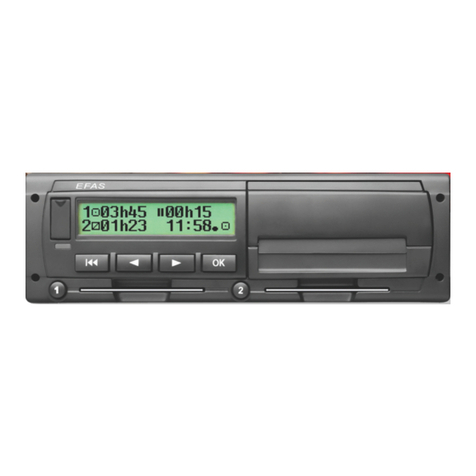
intellic Bosch EFAS-4.10 Instruction manual

Powered by
Workshop Manual
Smart Tachograph EFAS-4.10


Copyright
The information in this Service Manual may not be changed without the written permission of Intellic GmbH. Intellic GmbH
assumes no liability for this manual. The use and reproduction of this manual is only permissible in accordance with contractual
agreements.
This document may not be copied, reproduced, stored in a retrieval system or translated into another language, in any form,
either in part or in its entirety, without the written consent of Intellic GmbH.
Technical details of descriptions, specications and illustrations contained in this manual are subject to change without notice.
© Copyright 2011-2019 Intellic GmbH, Hausmannstätten, Austria
The terms and names used are registered trademarks and trade names are the property of their respective owners.
Intellic document number: 1250-131-SEC-EN01_WHB_E4_10
The smart tachograph EFAS-4.10 was developed by the intellicGermanyGmbH on behalf of Intellic GmbH based in Hausmann-
stätten/Austria and is marketed by the IntellicGmbH.
Manufacturer:
Intellic GmbH
Fernitzer Straße 5
8071 Hausmannstätten
Austria
www.intellic.com


Manufacturer’s declaration
We, Intellic GmbH in A-8071 Hausmannstätten, Austria, hereby declare that the device EFAS-4.10 complies with the provisions
of the following directives:
yREGULATION (EU) No 165/2014 OF THE EUROPEAN PARLIAMENT AND OF THE COUNCIL of 4 February 2014 on tacho-
graphs in road transport, repealing Council Regulation (EEC) No 3821/85 on recording equipment in road transport and
amending Regulation (EC) No 561/2006 of the European Parliament and of the Council on the harmonisation of certain
social legislation relating to road transport
yCOMMISSION IMPLEMENTING REGULATION (EU) 2016/799 of 18 March 2016 implementing Regulation (EU) No 165/2014
of the European Parliament and of the Council laying down the requirements for the construction, testing, installation,
operation and repair of tachographs and their components
replaced by
COMMISSION IMPLEMENTING REGULATION (EU) 2018/502 of 28 February 2018 amending Implementing Regulation (EU)
2016/799 laying down the requirements for the construction, testing, installation, operation and repair of tachographs
and their components
yUN ECE R10 Rev. 5 of the United Nations Economic Commission for Europe (UNECE) — Uniform provisions concerning
the approval of vehicles with regard to electromagnetic compatibility
yDIRECTIVE 2014/30/EU OF THE EUROPEAN PARLIAMENT AND OF THE COUNCIL of 26 February 2014 on the harmonisa-
tion of the laws of the Member States relating to electromagnetic compatibility (recast)
An examination for compliance with the above guidelines was carried out by the
TÜV NORD Mobilität GmbH & Co KG
IFM – Gesamtfahrzeug Sonderfahrzeuge, Nutzfahrzeuge, Krafträder
Am TÜV 1
30519 Hannover.


Table of content
Chapter 1 Introduction ......................................................................................................................................1
1.1 Target group ............................................................................................................................................................................. 1
1.2 Symbols...................................................................................................................................................................................... 1
Chapter 2 Legal requirements..........................................................................................................................2
2.1 European Union regulations.................................................................................................................................................. 2
2.1.1 Regulation (EU) No. 165/2014.................................................................................................................................................................. 2
2.1.2 Regulation (EU) No. 2016/799.................................................................................................................................................................. 2
2.1.3 Regulation (EU) No. 2018/502.................................................................................................................................................................. 2
2.1.4 Regulation (EC) No. 561/ 2006 ................................................................................................................................................................. 2
2.1.5 Directive 2002/15/EC................................................................................................................................................................................... 2
2.1.6 Directive 2014/30/EU .................................................................................................................................................................................. 2
2.2 AETR agreement....................................................................................................................................................................... 2
2.3 National regulations................................................................................................................................................................ 2
2.4 Standards and regulations for tachographs....................................................................................................................... 2
Chapter 3 General information on smart recording equipment ...............................................................4
3.1 General upgrading to smart recording equipment according to Regulation (EU) No 2016/799............................. 4
3.1.1 Exceptions from the obligatory use of recording equipment...................................................................................................... 4
3.2 Smart recording equipment .................................................................................................................................................. 5
3.2.1 Provisions for drivers and employers..................................................................................................................................................... 5
3.3 Description of the tachograph smart-cards........................................................................................................................ 5
3.3.1 Types of tachograph smart-cards ........................................................................................................................................................... 5
3.3.2 Handling the tachograph smart-cards.................................................................................................................................................. 6
3.4 Viewing, printing and storing the recorded data .............................................................................................................. 7
3.4.1 Viewing the data........................................................................................................................................................................................... 7
3.4.2 Handling the printouts ............................................................................................................................................................................... 7
3.4.3 Data download .............................................................................................................................................................................................. 7
3.4.4 Handling the data readouts...................................................................................................................................................................... 7
Chapter 4 Control elements and displays ......................................................................................................8
4.1 The EFAS smart tachograph................................................................................................................................................... 8
4.2 Keys............................................................................................................................................................................................. 8
4.3 Card readers.............................................................................................................................................................................. 9
4.4 Display........................................................................................................................................................................................ 9
4.5 Warning light and acoustic signals..................................................................................................................................... 10
4.6 Printer paper container......................................................................................................................................................... 10
4.7 Service port ............................................................................................................................................................................. 11
4.8 Working with menus ............................................................................................................................................................. 12
4.9 Using the tachograph smart-cards..................................................................................................................................... 12
4.9.1 Card combinations and their eect on the operating mode......................................................................................................13
Chapter 5 General instructions prior to installation ................................................................................. 14
5.1 Preparations for installation in the vehicle....................................................................................................................... 14
5.1.1 Receipt of device.........................................................................................................................................................................................14
5.1.2 Storage............................................................................................................................................................................................................14
5.1.3 Visual inspection before installation....................................................................................................................................................14
5.1.4 Details on the type label ..........................................................................................................................................................................15
5.1.5 Device versions............................................................................................................................................................................................15
5.1.5.1 Previous hardware and software versions.....................................................................................................................................15
Chapter 6 Installing and commissioning..................................................................................................... 16
6.1 Checks before installation.................................................................................................................................................... 16
6.2 Handling during installation................................................................................................................................................ 16
6.2.1 Connector panel..........................................................................................................................................................................................16
6.2.2 Pin assignment for the device................................................................................................................................................................17
6.2.2.1 Protection of positive and negative pole.......................................................................................................................................18
6.2.3 Motion sensor ..............................................................................................................................................................................................18
6.2.4 Mounting on the vehicle..........................................................................................................................................................................18

6.2.5 Conditions for switching-on and operating states.........................................................................................................................19
6.2.6 Changing the internal buer battery ..................................................................................................................................................19
6.2.6.1 Removing the internal buer battery .............................................................................................................................................19
6.2.6.2 Installing the battery .............................................................................................................................................................................20
6.2.7 Seals.................................................................................................................................................................................................................21
6.3 Preparation and conguration before activation of the control unit.......................................................................... 21
6.4 Activating the smart tachograph EFAS.............................................................................................................................. 21
6.4.1 Sample printouts“Technical Data.........................................................................................................................................................24
6.4.1.1 Before activation.....................................................................................................................................................................................25
6.4.1.2 Activation...................................................................................................................................................................................................25
6.4.1.3 Initial Installation ....................................................................................................................................................................................26
6.4.1.4 Calibration.................................................................................................................................................................................................27
6.4.1.5 Entry of the registration number by the vehicle holder...........................................................................................................28
6.5 Manual motion sensor pairing ............................................................................................................................................ 28
6.6 Installing the DSRC module ................................................................................................................................................. 30
6.6.1 Installation of the DSRC module according to EU regulation 2016/799.................................................................................30
6.6.2 Connection of the DSRC module ..........................................................................................................................................................30
Chapter 7 General settings............................................................................................................................. 31
7.1 Clock ......................................................................................................................................................................................... 31
7.1.1 Date and time...............................................................................................................................................................................................31
7.1.2 Time zone ......................................................................................................................................................................................................32
7.1.3 Daylight saving time..................................................................................................................................................................................32
7.1.4 Date format...................................................................................................................................................................................................32
7.2 Automatic activity setting after ignition OFF/ON............................................................................................................ 33
7.3 Blocking rst generation tachograph cards ..................................................................................................................... 33
7.4 Remote Data Downloading......................................................................................................................................... 33
7.5 Fleet Management System FMS.......................................................................................................................................... 33
7.6 Removing the printer paper container and inserting the printer paper roll.............................................................. 34
Chapter 8 Parameter conguration.............................................................................................................. 35
8.1 Access rights ........................................................................................................................................................................... 35
8.2 Ranges of values and lengths.............................................................................................................................................. 35
8.3 Parameters for vehicle adaptation and for connecting external devices ................................................................... 35
8.3.1 Nominal voltage of the vehicle (on-board power supply) (RDI=0xFDA3)..............................................................................36
8.3.2 CAN-bus conguration of the main CAN vehicle bus (CAN MAIN)...........................................................................................36
8.3.3 CAN-bus conguration of the auxiliary CAN expansion bus (CAN AUX)................................................................................37
8.3.4 Wake-up via CAN-bus (RDI=0xFD6D)..................................................................................................................................................37
8.3.5 Source to reset the trip distance motion sensor (RDI=0xFD00).................................................................................................37
8.3.6 Source of lighting control (RDI=0xFD34) ...........................................................................................................................................37
8.3.7 Operating mode of the input A2 for lighting control (RDI=0xFDA1).......................................................................................37
8.3.8 PWM conguration for lighting control..............................................................................................................................................37
8.3.9 Factor for calculating the speed of the output shaft (RDI=0xF91E) .........................................................................................37
8.3.10 Selection of engine-speed data source (RCI=0xFD3A) .................................................................................................................38
8.3.11 Engine speed factor (n-factor) (RDI=0xFD32)...................................................................................................................................38
8.3.12 Conguration of the serial interface on D7 (RDI=0xFD26)..........................................................................................................38
8.3.13 Conguration of the serial interface on D8 (RDI=0xFD26)..........................................................................................................38
8.3.14 Monitoring of pulse output B7 (RDI=0xFD35)..................................................................................................................................38
8.3.15 Function of the pulse output D6 (RDI=0xFDA0)..............................................................................................................................38
8.3.16 CAN Heart beat monitoring of a connected bus subscriber (RDI=0xF90C) ..........................................................................38
8.3.17 Transmission interval of the TCO1 message (RDI=0xF920) .........................................................................................................38
8.3.18 Conguration of FMS service (RDI=0xFD9E).....................................................................................................................................38
8.4 Automatic Parameters Detection ....................................................................................................................................... 39
Chapter 9 Calibration ...................................................................................................................................... 40
9.1 Conguration with factory settings ................................................................................................................................... 40
9.2 Preparatory actions ............................................................................................................................................................... 40
9.2.1 Visual inspection.........................................................................................................................................................................................40
9.2.2 Inspection of the seals and installation plaque ...............................................................................................................................40
9.2.3 Data read-out ...............................................................................................................................................................................................41
9.2.4 Check internal buer battery .................................................................................................................................................................41
9.3 Test equipment....................................................................................................................................................................... 41
9.4 Calibrating the EFAS .............................................................................................................................................................. 41

9.5 Prüfung des GNSS-Moduls................................................................................................................................................... 42
9.6 Prüfung des DSRC-Moduls ................................................................................................................................................... 42
9.7 Test drive.................................................................................................................................................................................. 42
9.8 Installation plaque................................................................................................................................................................. 42
Chapter 10 Fault diagnosis............................................................................................................................... 43
10.1 Events, malfunctions, and operating instructions in general ....................................................................................... 43
10.2 Error code types ..................................................................................................................................................................... 43
10.3 Display of events and malfunctions ................................................................................................................................... 44
10.3.1 Displays in the OPERATIONAL mode ...................................................................................................................................................44
10.3.2 Displays in the CALIBRATION mode and before activation.........................................................................................................45
10.3.3 Displays in the event of serious malfunctions..................................................................................................................................45
10.4 General debugging procedure............................................................................................................................................ 45
10.5 Tools for error diagnosis ....................................................................................................................................................... 46
10.6 Integrated test functions...................................................................................................................................................... 46
10.6.1 Overview........................................................................................................................................................................................................46
10.6.2 Printer test.....................................................................................................................................................................................................47
10.6.3 Card reading test.........................................................................................................................................................................................47
10.6.4 Display unit test...........................................................................................................................................................................................48
10.6.5 Keyboard test ...............................................................................................................................................................................................48
10.6.6 General hardware test...............................................................................................................................................................................48
10.6.7 Testing the warning lamp and the acoustic alarm .........................................................................................................................49
10.6.8 Testing the engine-speed signal source.............................................................................................................................................49
10.6.9 Testing the on-board power supply.....................................................................................................................................................49
10.6.10 Testing for digital inputs/outputs at the connector panel ..........................................................................................................50
10.6.11 Testing the rotational speed of the output shaft ............................................................................................................................50
10.6.12 Testing the motion sensor interface ....................................................................................................................................................50
10.6.13 Testing the internal back-up battery ...................................................................................................................................................50
10.6.14 Testing the pulse outputs........................................................................................................................................................................50
10.6.15 GNSS Test .......................................................................................................................................................................................................51
10.6.16 DSRC Test (Equipment for remote communication)......................................................................................................................51
10.6.17 CAN Test .........................................................................................................................................................................................................52
Chapter 11 Repair options................................................................................................................................ 53
11.1 Removing the tachograph ................................................................................................................................................... 53
11.2 Removing a jammed smart-card......................................................................................................................................... 53
11.3 Replacing the buer battery................................................................................................................................................ 54
11.4 Repairs that cannot be carried out in the workshop....................................................................................................... 54
11.5 Decommissioning tachographs .......................................................................................................................................... 54
11.6 Warranty .................................................................................................................................................................................. 55
11.7 Exclusion of warranty............................................................................................................................................................ 55
Chapter 12 List of the events/malfunctions and measures for trouble-shooting ................................. 56
12.1 EFT summary table ................................................................................................................................................................ 56
12.2 Overview of Service IDs ........................................................................................................................................................ 57
12.3 DTC overview table................................................................................................................................................................ 77
12.4 Printout of Service IDs........................................................................................................................................................... 79
12.5 Support during installation and operation of the tachograph..................................................................................... 80
Chapter 13 Interfaces ........................................................................................................................................ 81
13.1 CAN bus.................................................................................................................................................................................... 81
13.1.1 Overview........................................................................................................................................................................................................81
13.1.2 CAN bus terminating resistors ...............................................................................................................................................................81
13.1.3 Data..................................................................................................................................................................................................................82
13.1.4 CAN parameters ..........................................................................................................................................................................................83
13.2 Serial interfaces D7 and D8.................................................................................................................................................. 84
13.2.1 Protocol, information interface..............................................................................................................................................................85
13.2.2 Protocol, k-line .............................................................................................................................................................................................85
13.3 Pulse interfaces B6, B7, B8, D6............................................................................................................................................. 85
13.3.1 Speed-coding outputs B6, B7.................................................................................................................................................................85
13.3.2 Speed-coding output D6 .........................................................................................................................................................................85
13.3.3 Distance encoding output B8.................................................................................................................................................................86

Chapter 14 Additional data recording ........................................................................................................... 87
14.1 Logging vehicle speed (v-prole) ....................................................................................................................................... 87
14.2 Logging engine speed (n-prole) ....................................................................................................................................... 87
14.3 Logging the two status inputs D1 and D2......................................................................................................................... 88
Chapter 15 Driver’s times summary ( iCounter )............................................................................... 89
Chapter 16 Updating the EFAS operating software..................................................................................... 90
16.1 Requirements ......................................................................................................................................................................... 90
16.2 Display device data................................................................................................................................................................ 90
16.3 Downloading new software from the manufacturer...................................................................................................... 90
16.4 Uploading the software into the device............................................................................................................................ 90
16.5 Finishing the software update ............................................................................................................................................ 91
Chapter 17 National / regional abbreviations and European time zones ............................................... 92
Chapter 18 Technical data ................................................................................................................................ 94
Chapter 19 Menu structure in EFAS ................................................................................................................ 95
Chapter 20 Symbols and what they mean..................................................................................................... 96
20.1 Persons, activities and operating modes .......................................................................................................................... 96
20.2 Tachograph smart-cards....................................................................................................................................................... 96
20.3 Activities .................................................................................................................................................................................. 96
20.4 Component designations..................................................................................................................................................... 96
20.5 Special conditions.................................................................................................................................................................. 97
20.6 Miscellaneous ......................................................................................................................................................................... 97
20.7 Error messages ....................................................................................................................................................................... 97
20.8 Time intervals ......................................................................................................................................................................... 98
20.9 Symbol combinations ........................................................................................................................................................... 98
20.10 Driving...................................................................................................................................................................................... 98
20.11 Printouts .................................................................................................................................................................................. 99
20.12 Event messages ...................................................................................................................................................................... 99
20.13 Malfunction messages .......................................................................................................................................................... 99
20.14 Marking of manual entries.................................................................................................................................................100
20.15 Messages while printing.....................................................................................................................................................100
List of abbreviations ........................................................................................................................................... 101
List of gures........................................................................................................................................................ 102
List of tables ......................................................................................................................................................... 104
Index ......................................................................................................................................................... 105

1
Workshop Manual
Digital Tachograph EFAS-4.10
Chapter 1 Introduction
The smart tachograph EFAS-4.10, referred to in the following as EFAS, logs information on the time that the driver and co-driver
spend driving, working, resting, and on standby. EFAS also automatically records the vehicle’s speed and the distance traveled.
The data recorded by EFAS serves as documentation for controlling bodies such as the police.
The EFAS smart tachograph complies with Commission implementing regulation (EU) 2016/799 of 18 March 2016 implementing
Regulation (EU) No 165/2014 of the European Parliament and of the Council laying down the requirements for the construction,
testing, installation, operation and repair of tachographs and their components as well as Commission implementing regula-
tion (EU) 2018/502 of 28 February 2018 amending Implementing Regulation (EU) 2016/799 laying down the requirements for
the construction, testing, installation, operation and repair of tachographs and their components
This EFAS Smart Tachograph Workshop Manual is intended to serve as a reference work for any general questions concerning
recording equipment and for specic questions concerning the EFAS Smart Tachograph. The Workshop Manual provides
answers to questions on the statutory framework, explains the individual functions and menu settings of the EFAS device and
gives information and assistance for the installation, use, calibration and repair options of the EFAS Smart Tachograph, including
how to update the EFAS application software.
This workshop manual describes the functions and characteristics of the EFAS smart tachograph of hardware
revisions4.10 with the software version V05.00.
1.1 Target group
This Workshop Manual is aimed at users authorized to install recording equipment in vehicles, to replace them when defective
and to perform calibrations of the smart tachograph in accordance with legal regulations. Primarily these are workshop per-
sonnel who have the appropriate, legally prescribed equipment and tools required to install, inspect and calibrate recording
equipment. Such functions may only be carried out by workshop personnel who have appropriate training certication and
who are in possession of a valid workshop smart-card.
This Workshop Manual also provides assistance to personnel of vehicle manufacturers who install the EFAS Smart Tachograph
into the vehicle during production and who perform the basic conguration.
1.2 Symbols
This section explains the special symbols used to emphasize certain parts of the Workshop Manual.
The appropriate symbols are pictured in the column on the left. The text column on the right contains the relevant explanations
and the warnings.
Symbol Meaning Description
Hazard There is a danger of injury or accident.
Warning Malfunction of the tachograph or of the vehicle is possible.
Note Important information or advice on how to avoid malfunctions.

2
Workshop Manual
Digital Tachograph EFAS-4.10
Chapter 2 Legal requirements
This chapter describes the most important European regulations that must be considered in connection with the use of smart
tachographs. The EU regulations are generally supplemented with national legislation in the member states and this must also
be observed.
2.1 European Union regulations
The European Union regulations listed below are binding on all member states with regard to the creation and monitoring of
uniform working conditions for drivers.
2.1.1 Regulation (EU) No. 165/2014
Regulation (EU) No. 165/2014 on tachographs in road transport, repealing Council Regulation (EEC) No 3821/85 on recording
equipment in road transport and amending Regulation (EC) No 561/2006 of the European Parliament and of the Council on the
harmonisation of certain social legislation relating to road transport.
2.1.2 Regulation (EU) No. 2016/799
Commission implementing Regulation (EU) No. 2016/799 laying down the requirements for the construction, testing, installa-
tion, operation and repair of tachographs and their components.
2.1.3 Regulation (EU) No. 2018/502
Commission implementing Regulation (EU) No. 2018/502 amending Implementing Regulation (EU) 2016/799 laying down the
requirements for the construction, testing, installation, operation and repair of tachographs and their components.
2.1.4 Regulation (EC) No. 561/ 2006
Regulation (EC) No. 561/2006 of the European Parliament and of the Council of 15 March 2006 on the harmonization of certain
social legislation relating to road transport includes provisions for the working times of drivers involved in the carriage of
goods and passengers and their supervision. This regulation also species those vehicles exempted from the obligation to have
equipment tted.
2.1.5 Directive 2002/15/EC
Directive 2002/15/EC of the European Parliament and of the Council of 11 March 2002 on the organization of working time of
persons performing mobile road transport activities includes requirements relating to their working times and how these are
recorded. The Directive is backed up by domestic legislation in the member states of the European Union.
2.1.6 Directive 2014/30/EU
The Directive 2014/30/EU of the European Parliament and of the Council of 26 February 2014 on the harmonisation of the laws
of the Member States relating to electromagnetic compatibility (recast).
2.2 AETR agreement
The European Agreement concerning the work of crews of vehicles engaged in international road transport contains the
provisions relating to the employment of drivers in the carriage of goods and passengers and their supervision outside of the
European Union. Further information can be found at www.unece.org in the document‘ECE/TRANS/ SC.1/2006/2’.
2.3 National regulations
National legislation is passed to supplement the regulations of the European Union and are applied in the countries concerned.
Please obtain sucient relevant information about the national laws that apply in your own country.
2.4 Standards and regulations for tachographs
The EFAS Smart Tachograph complies with the following standards and regulations:
yDIN EN 60079-0: 06.2014
Electrical apparatus for explosive gas atmospheres -

3
Workshop Manual
Digital Tachograph EFAS-4.10
Part 0: General requirements
yDIN EN 60079-11: 06.2012
Explosive atmospheres -
Part 11: Equipment protection by intrinsic safety“I”
yDIN EN 60079-15: 02.2011
Electrical apparatus for explosive gas atmospheres -
Part 15: Construction, test and marking of type of protection “n” electrical apparatus
yUN ECE R10 Rev. 5 of the United Nations Economic Commission for Europe (UNECE) — Uniform provisions concerning
the approval of vehicles with regard to electromagnetic compatibility [2017/260]

4
Workshop Manual
Digital Tachograph EFAS-4.10
Chapter 3 General information on smart recording equipment
3.1 General upgrading to smart recording equipment according to Regulation (EU) No 2016/799
The rst generation digital tachograph system has been deployed since 1 May 2006. It may be used until its end of life for
domestic transportation. For international transportation, instead, 15 years after the entry into force of this Commission Reg-
ulation, all vehicles shall be equipped with a compliant second generation smart tachograph, introduced by this Regulation.
This Annex contains second generation recording equipment and tachograph cards requirements. Starting from its introduc-
tion date, second generation recording equipment shall be installed in vehicles registered for the rst time, and second gener-
ation tachograph cards shall be issued.
yIn order to foster a smooth introduction of the second generation tachograph system second generation tachograph
cards shall be designed to be also used in rst generation vehicle units,
yreplacement of valid rst generation tachograph cards at the introduction date shall not be requested.
This will allow drivers to keep their unique driver card and use both systems with it. Second generation recording equipment
shall however only be calibrated using second generation workshop cards.
3.1.1 Exceptions from the obligatory use of recording equipment
As already described in section3.1, there is a general obligation to t all vehicles registered after May 1, 2006 with digital
recording equipment. This applies to all vehicles and vehicle units used for the transport of goods whose maximum authorized
mass including trailer or semi-trailer exceeds 3.5tonnes and to vehicles with more than 9 passenger seats (including the driver)
used for the conveyance of passengers.
Notwithstanding this, there is a special arrangement for vehicles that for example are exempted owing to their special area of
operation. These exceptions are dealt with in Regulation (EC) No. 561/2006 and Regulation (EU) No.165/2014 in combination
with Regulation (EEC) 3820/85 and in the German Regulations on Drivers (FPersV).
You can nd a detailed list of exceptions to the compulsory installation of smart tachographs in Europe here:
Europe1:REG (EC) 561/2006 Articles 3 and 13 (1) and REG (EU) 165/2014
The following is an overview of exceptions to the compulsory use of smart tachographs in Europe:
yUsed for transporting goods with a maximum permissible weight of not more than 3.5tonnes including trailer
yUsed for transporting passengers with a maximum of 9 passenger seats (including driver)
yUsed for transporting passengers in a regular service when the route is less than 50km
yUsed for a maximum permissible speed of no more than 40km/h
yUsed by the armed forces, civil defense, re brigade or police
yUsed specially for breakdown recovery within a radius of 100 km of their home base
yUsed in emergencies or for rescue services and as well as special-purpose medical vehicles
yUsed for test driving during technical development as well as new and converted vehicles (prototypes) that have not yet
been certied
yUsed in tests following repairs and maintenance
yUsed for the non-commercial carriage of goods with a maximum permissible weight of 7.5tonnes (applies to single
vehicles and combinations of vehicles)
yUsed for driving instruction by learner drivers and instructors or for obtaining a certicate of professional competence
yClassied as historic commercial vehicles under domestic legislation and which are not operated for the commercial
transport of goods or passengers
yThose used in the non-commercial transport of humanitarian aid
yVehicles with a maximum permissible mass not exceeding 7,5 tonnes used for carrying materials, equipment or machinery
for the driver’s use in the course of his work, and which are used only within a 100km radius from the base of the under-
taking, on condition that driving such vehicles does not constitute the driver’s main activity.
1 Country-specic exceptions may apply

5
Workshop Manual
Digital Tachograph EFAS-4.10
3.2 Smart recording equipment
Smart recording equipment includes certain devices that are suitable for the fully or partly automatic display, recording and
storage of details concerning a vehicle’s journey and concerning certain working times of the driver.
Recording equipment consists of the tachograph, connection cables and a motion sensor (pulse generator) as well as a DSRC
facility, a GNSS receiver and an optional ITS interface.
The driver’s activity-related data is stored on the driver smart-card.Vehicle-related data including speed, distance driven, vehicle
mileage etc. is saved to the recording equipment’s mass memory.
The following data is stored to mass memory:
yEquipment identication data (Vehicle unit identication data, Motion sensor identication data, Global Navigation Sat-
ellite Systems identication data)
yKeys and certicates
yDriver or workshop card insertion and withdrawal data
yDriver activity data
yPlaces and positions where daily work periods begin, end, and/or where 3 hours’continuous driving time is reached
yOdometer data
yDetailed speed data
yEvents data
yFaults data
yCalibration data
yTime adjustment data
yControl activity data (relevant to the 20 most recent control activities)
yCompany locks data (relevant to the 255 most recent company locks)
yDownload activity data (relevant to the last data memory downloading to external media while in company or in cali-
bration mode)
ySpecic conditions data
yTachograph card data
3.2.1 Provisions for drivers and employers
The use of analogue, digital or smart tachographs is governed by EC Regulation 3821/85 Appendix IB and 3820/85 as well as
by implementing Regulation (EU) 2016/799 and implementing Regulation (EU) 2018/502. This regulation imposes a number
of obligations on both the driver and the owner of the vehicle. The following sections are not exhaustive and are not legally
denitive. The information is intended as general introduction only.
Modications to the recording equipment or to the signals used, in particular with fraudulent intent, are punishable by law. The
forgery, suppression or destruction of recordings stored in the recording equipment or on driver smart-cards or of printouts is
forbidden. Please take time to acquaint yourself with current legal provisions before using the recording equipment.
In the event of disruptions to the recording equipment, e.g. when the internal clock shows a signicant time dierence, the
recording equipment must be checked immediately by an authorized workshop.
If data required for recording is changed on the vehicle, e.g. tire circumference, motion sensor or the ocial registration number,
these changes must be entered in the smart tachograph by an authorized workshop.
3.3 Description of the tachograph smart-cards
Tachograph smart-cards are electronic smart-cards that are used to identify the user to the smart tachograph and on which
certain data is stored for retrieval.
3.3.1 Types of tachograph smart-cards
There are four dierent types of tachograph smart-cards that are marked with four dierent colors.
yDriver’s smart-card (white) OPERATION

6
Workshop Manual
Digital Tachograph EFAS-4.10
yWorkshop smart-card (red) CALIBRATION
yCompany smart-card (yellow) COMPANY
yControl smart-card (blue) CONTROL
The mode of operation of the smart tachograph is set depending on which type of tachograph smart-card is inserted and is
indicated by a symbol in the display.
The special features and areas of application of the various tachograph smart-cards are explained below.
Driver smart-card (white)
A driver’s smart-card is used to identify the driver to the smart tachograph. The driver’s smart-card is used for normal driving
operation. It is used to display, store and print out the activities of the driver and co-driver. Data on the driver smart-card must
be read out at least once every 28 days.
The driver smart-card is the driver’s personal property. It may not be passed on to third parties. Each driver may only hold one
valid driver’s smart-card. A driver’s smart-card is valid for 5 years.
Company smart-card (yellow)
The company smart-card identies the respective commercial-vehicle company. It entitles a company to access the data of
the respective company. The company smart-card allows data from the recording equipment to be displayed, printed out and
downloaded. It is intended for use only by the vehicle owner and is only issued to the owners of companies or businesses or to
vehicle keepers.
A company can own up to 62 company smart-cards. The company is obliged to ensure that all drivers are trained in the opera-
tion of smart tachographs and that they have sucient rolls of printing paper with them.
It must be possible to make the data from the smart tachograph available to inspection authorities at any time. Company smart-
cards are valid for 5 years.
Control smart-card (blue)
The control smart-card is used for identication purposes by controlling bodies such as the police. With the control smart-card,
all of the data stored in the smart tachograph (mass memory data) and on the driver’s smart-card can be displayed, printed out
or downloaded.
The control smart-card assists in carrying out tachograph checks. It is valid for 2 years.
Workshop smart-card (red)
The workshop smart-cards are intended for use by the personnel of authorized workshops. A workshop smart-card allows a
smart tachograph to be activated, checked and calibrated. In contrast to the company and control smart-cards, the workshop
smart-card can be used for test drive purposes.
A workshop smart-card identies the appropriate specialist of an approved or authorized workshop. Each employee of a
workshop may only possess one valid workshop smart-card (per workshop), i.e. if an employee has several employers (=work-
shops), a workshop smart-card can be issued for each workshop. The PIN of a workshop smart-card is only issued to the cor-
responding specialist owning the workshop smart-card. If the smart-card is lost or damaged or if the PIN is forgotten, the
appropriate authorities must be notied immediately and a new card must be applied for.
A workshop smart-card is valid for 1 years.
Note Driver, control and workshop smart-cards are issued to specic individuals. These smart-cards may not be
passed on to other persons.
Note The company smart-card (yellow) and the control smart-card (blue) may not be used to drive.
3.3.2 Handling the tachograph smart-cards
Please observe the following rules when handling tachograph smart-cards:
yAvoid bending or exing tachograph smart-cards.
yDo not insert damaged or soiled tachograph smart-cards into the recording equipment.
yKeep the contact surface clean, dry and free from oil or grease. Always keep a tachograph smart-card in its protective
cover.
yUse a damp cloth to clean recording device smart-cards that been accidentally soiled, the front cover and the display
window. Do not use any solvents or abrasive cleaning agents.
yAvoid exposing the tachograph smart-cards to sunlight and electromagnetic elds. Do not leave a tachograph smart-card

7
Workshop Manual
Digital Tachograph EFAS-4.10
lying on the dashboard.
yDo not use tachograph smart-cards beyond their expiry date. Apply for a new tachograph smart-card in good time.
3.4 Viewing, printing and storing the recorded data
Depending on which type of tachograph smart-card is inserted, vehicle-related data can be read out of the mass memory and
driver-related data read out of the driver’s smart-card and then displayed, printed or downloaded.
3.4.1 Viewing the data
Various parameters can be shown in the display. The display is situated in the driver’s immediate eld of view and can be set to
display the desired information using operating keys.
3.4.2 Handling the printouts
The data in mass memory and the data on the driver’s smart-card can be printed out via an integrated printer module. Only
authorized printer paper is to be used for smart tachograph printouts, and this is recognizable by the certication mark on the
back of the paper. It is a special type of thermal printing paper.
Note Printouts are made using thermal printing paper. A printout can become unreadable through the eects of
warmth, sunlight, moisture or chemicals.
Please observe the following rules when handling printouts:
yAvoid exposing the printouts to sunlight, direct light, moisture and warmth.
yDo not use any text highlighters on the printouts.
3.4.3 Data download
Data in the mass memory must be read out at least once every three months and archived by the vehicle owner. Data read out
in this way must be stored in a safe location for a period of 2 years. It must always be possible to make this data available to
inspection authorities at any time.
Reading data out of mass memory is performed for example via the front-mounted download interface (standard six-pin inter-
face). The downloaded data can be stored and archived on an external storage medium.
Downloading the data does not change or delete the data in mass memory. The mass memory can store around 365 days of
data when the smart tachograph sees average use. After the 365 days, the device begins overwriting the rst day’s data, then
those of the second day and so on.
Driver smart-card data can be read out with a special reader or via the smart tachograph and archived on an external storage
device. Like mass memory data, driver smart-card data must be kept for a period of two years. It must always be possible to
make this data available at the request of the regulatory authorities.
Similar to the download of the data from the mass memory, driver smart-card data are also not changed or deleted when
downloaded. The driver smart-card data must be read out every 28 days and archived.
3.4.4 Handling the data readouts
If a tachograph has to be replaced, you are obliged to copy the data with the assistance of a workshop smart-card and to save it
on an external storage medium. Reading data out is eected via the standard six-pin service interface on the front of the device.
Data in the recording device’s mass memory is only copied, it is not modied. It can be downloaded using any normal, com-
mercially available equipment (PC software and serial cable, or your service partner’s download key). The data must be made
available to the transportation company and must be archived for a period of 2 years. The data must be destroyed at the end of
the archival period.
If it is not possible to download the data, you must issue a certicate in accordance with Appendix XVIII of the StVZO and present
this to the transportation company. This will serve as proof for the company in the event of an inspection by the authorities that
the data could not be archived. A copy of the document must be kept for a period of one year.

8
Workshop Manual
Digital Tachograph EFAS-4.10
Chapter 4 Control elements and displays
4.1 The EFAS smart tachograph
The EFAS smart tachograph has a two-line LCD display, two slots for tachograph smart-cards, a front-mounted interface for
calibration and downloading, a printing module, and 6 operating keys. It can be installed in a standard-sized car stereo slot.
Warning alerts can be emitted optically and acoustically.
The EFAS smart tachograph is activated when
ythe vehicle’s ignition is turned on,
yby signals from the motion sensor,
ywhen a tachograph smart-card is inserted,
ywhen any of the keys is pressed or
ythrough an FMS download,
yat the end of a 45-minute drive break.
To remove the tachograph card, the vehicle must be stationary (0 km/h) and the ignition turned on (level 1). At the latest
4minutes after the ignition is switched o, EFAS switches o automatically. If a key is pressed after turning o the ignition, the
shutdown of EFAS is delayed by up to 4 minutes.The time for EFAS to switch o after switching o the ignition can be congured.
The following sections describe the EFAS device’s control elements and displays:
yKeys (section 4.2)
yCard readers (section 4.3)
yDisplay (section 4.4)
yWarning light and acoustic signals (section 4.5)
yPrinter module (section 4.6)
yService interface (section 4.7)
yWorking with menus (section 4.8)
yUsing the tachograph smart-cards (section 4.9)
4.2 Keys
The EFAS smart tachograph is operated using the six keys on the front of the device:
Figure 1 — Keys
The individual keys have the following functions:
Key Meaning Description
Key for driver 1 Referred to in the text below as: u
By briey pressing the button, the driver activity (working time, standby time and rest time) can
be selected for driver 1. The activity only changes after the key is released. Pressing the key for
at least 1.5 seconds when the vehicle is stationary requests the card to be ejected from slot 1.

9
Workshop Manual
Digital Tachograph EFAS-4.10
Key Meaning Description
Key for driver 2 Referred to in the text below as: v
By briey pressing the button, the driver activity (working time, standby time and rest time)
can be selected for driver 2. The activity only cycles to the next one after the key is released.
Pressing the key for at least 1.5 seconds when the vehicle is stationary requests the card to be
ejected from slot 2.
OK key Referred to in the text below as: OK
When the vehicle is stationary: Calls the main menus and/or conrms any entries.
During a journey: Stores the current speed for individual speed monitoring2of the driver.
BACK key Referred to in the text below as: 9
When the vehicle is stationary:
yCancel a selected function within a menu / go back one menu level.
yTerminates a menu if pressed for approx. 1 second.
ySets the local language for the display to English if held pressed for at least 5 seconds
when the standard display can be seen.
During a journey: Switches individually programmed speed monitoring o.
Control key Referred to in the text below as:
Selects the next menu item, switches the screen display
Control key Referred to in the text below as:
Selects the previous menu item, switches the screen display
2
4.3 Card readers
EFAS is tted with two card readers.
Figure 2 — Card readers
The card slot for the driver is on the left and for the co-driver on the right. Each card must be inserted all the way to the stop.
The cards are locked mechanically and normally they can only be removed electrically with the help of the application when the
vehicle is stationary. To remove jammed cards see section 11.2.
4.4 Display
The EFAS smart tachograph has an alphanumeric monochrome graphics-capable LCD. The color of the back-lighting is a device
option and is set at the factory. It cannot be altered subsequently.
Figure 3 — Alphanumeric display
2 PersonalSpeedWarning: Can be programmed via EFAS Service Tool, see Settings gWarning

10
Workshop Manual
Digital Tachograph EFAS-4.10
Text is displayed in the local language as congured.The language is set based on the local language of the driver’s or workshop
smart-card or it can be selected via the main menu.
4.5 Warning light and acoustic signals
The red warning light displays various operating states of the EFAS smart tachograph. In the default conguration, certain
operating states are indicated with an acoustic signal. If required, the acoustic signals can be enabled or disabled in the menu or
alternatively as a parameter setting via the service interface. The settings for acoustic signaling are made in the device menu or
alternatively as a parameter specication via the programming interface. Besides the smart tachograph’s signals, the alarm is in
some cases triggered on the alarm output pin D4 of the D connector panel.The alarm output can be used to activate an external
alarm display e.g. a warning light on the instrument panel or in the tachometer display.
Figure 4 — Red warning lights to display the operational status
The table below summarizes the various operating states of the warning light and their meanings:
Table 1 — Warning light and acoustic signals
LED Tone/series of tones Meaning / Operating state
Function check
O -Ready for operation and no active alarms (device is activated or in standby mode).
Blinks RED 1x - The LED blinks briey as a function check when the tachograph is switched on.
- 3x long The connection to the front module is faulty. LCD display is faulty or not possible.
Blinks RED - The LED blinks briey with long breaks in between. There is a serious defect with
the hardware. The LCD display remains dark after the device is switched on. The
tachograph must be replaced.
Alarms
Blinks RED 1x long, 2x short Event or malfunction message as per REG (EC) No. 1360/ 2002. LED blinks for a
maximum of 30 seconds until the cause of the alarm is acknowledged with OK.
Alarm output pin D4 is set to active.
RED 2x short, 1x long In combination with the text display “Service”. There is a serious defect with
the hardware. The tachograph must be taken to a workshop for repair and may
have to be replaced.
Blinks RED 1x long Individually programmed speed has been exceeded >> or advance warning of
maximum speed limit being exceeded with“> EF-Info <“ in the display.
Blinks RED 2x 1x short Alarm issued after incorrect input.
Acknowledgments, Input aids (information)
- 1x short Acknowledgment signal for successful input.
- 1x long Incorrect operation. Occurs when a key is pressed that is not supported in the
current dialog.
Blinks RED 1x short
(or several times)
Prompt for required user input.
Key click
- 1x short/quiet Key click when key is pressed
4.6 Printer paper container
With the built-in printer, the times recorded by the tachograph can be printed out, among other things. The paper container
can be removed to rell a roll of paper.
Table of contents
Other intellic Measuring Instrument manuals
