Trine AXION Series User manual

Index No.
Name Part Number
PARTS LIST
1Latch EN-430/435-LCH
2Slider EN-430/435-SLR
3Coil Assembly (12 V) EN-CA-12AC EN-CA-12DC
Coil Assembly (24 V) EN-CA-24AC EN-CA-24DC
4Screw 4-40 x 1/8 (Cover) EN-SCR.1/8
5Frame Cover EN-FR.C
6Screw 4-40 x 1/4 (Coil) EN-SCR.1/4
7Frame EN-F430, F435 (Specify LH or RH)
8Assembly Pin* EN-ASS.PN
9Spring EN-SPR
10 Latch Pivot Shaft EN-LCH-PV-ST
11 Guard EN-GRD
12 Face Plate EN-430FACE, 435FACE
13 Mounting Screws (2) 12-24-1/2” EN-MTS
14 Shim Kit (4) 1/16” Shim EN-UNV-SHIM
15 Shim Screws (2) 6-32-1/4” EN-SHIM-SCR-S
16 Shim Screws (2) 6-32-3/8” EN-SHIM-SCR-L
NOTE: Number in parenthesis ( ) indicates
part in Parts List.
UL LISTED – 10B fire rated (class A, 3-hour,
Single Swing Doors)
UL LISTED – 1034 Burglary Resistant Locking
Mechanism for Indoor or Outdoor Use
ANSI/BHMA A156.5-1992 – 4-7/8” X 1-1/4” Fits
Cutout Specification A115.1 (with Slight Jamb
Modification)
BHMA – Grade1
NYC MEA 79-01-E
NOTE: UL 10B fire listing is void when using
fail safe action.
* NOT PART OF ASSEMBLY. USED ONLY DURING DISASSEMBLY OR REPAIR.
** UNLESS OTHERWISE SPECIFIED, FRAME IS SUPPLIED AS SATIN STAINLESS STEEL -
US32D. SPECIFY OTHER FINISHES AS FOLLOWS: BRIGHT BRASS - US3;
SATIN BRASS - US4; DARK BRONZE -10B; BRIGHT CHROME -US26.
Instruction Manual
Figure 1
EN430 Electric Strike
8*
3
AXION SERIES - ELECTRIC STRIKE
MODEL EN 430/435
TRINE ACCESS TECHNOLOGY
1440 Ferris Place, Bronx, NY 10461-3699
Phone: 718 829-2332 Fax: 718 829-6405
www.trineonline.com

HAND OF DOOR IS ALWAYS DETERMINED
FROM THE OUTSIDE
Figure 2. Door Handing Positions
Spring
Tail
Latch
Fail Secure
6A
Fail Safe
6B
Figure 3. Position of Electric Strike
for Right Handed Door.
Wiring
Latch
Wiring
Latch
Latch Side
Dimple
Fail Secure Fail Safe
HANDING DETERMINATION
The handing of a door is determined
by the position of the hinges, as
viewed from the outside of the room,
building, office, etc. If the door hinges
are on the left, the door is termed
left-handed; if the door hinges are on
the right, the door is termed right-
handed. In addition, a door is either
inswinging (opens into the room), or
outswinging (opens to the outside of
the room), as illustrated in Figure 2.
NOTE
The EN430 and 435 are available
in either LH (Left-handed) or RH
(Right-handed). This needs to be
specified when ordering.
The position of the Electric Strike
within the door jamb will be the same
for a right-handed inswinging door and
a left-handed outswinging door. For
these installations, the Electric Strike
position within the door jamb will be as
viewed in Figure 3.
In a similar manner, the position of the
Electric Strike within the door jamb will
be the same for a left-handed inswinging
door and a right-handed outswinging
door. For these installations, the
Electric Strike position within the door
jamb will be as viewed in Figure 4.
Figure 4.
Position of
Electric Strike
for Left
Handed Door
ACTION (FAIL SECURE OR FAIL
SAFE)
The standard action is fail secure and is
field changeable to fail safe when
replaced with special order part
EN-SLR-RS. When using the fail safe
Slider, a DC Coil must be used.
The fail safe Slider is identified by the
small dimple below the welded tip.
CHANGING THE ACTION
1. Place Electric Strike face down
and, from back of assembly,
remove Screw (4) from Frame
Cover (5). Remove Frame Cover
from Electric Strike.
2. On side of Electric Strike, remove
Screw (6), which holds Coil Assembly
(3) to Frame (7).
3. Remove Coil Assembly from Electric
Strike.
NOTE
The Latch (1) is removed in the
following step. Assembly Pin (8) is
pushed through Latch to keep
Spring (9) in place. If Assembly
Pin is not available, use care when
removing Latch Pivot Shaft (10) to
keep Spring within Latch. If Spring
comes out of Latch, reinstall
Spring as shown in Figure 5.
The four EN latch shims provide
cavity width adjustment in 1/16”
incraments.
From top of frame remove Slider (2)
from beneath Guard (11). Figure 6A.
Take replacement fail safe Slider and
insert through top opening with welded
tip in upright position. Make sure the
Slider rests on the bottom of the cavity.
Figure 6B.
Place Electric Strike on a flat surface
with front of frame (7) facing up and
insert Assembly Pin (8) into Latch to
push out Latch Pivot Shaft (10).
Remove Latch (1) containing Assembly
Pin.
Figure 6.
Slider and Guard Positions
Hold Latch by satin side and roll into
frame cavity with back end and
exposed tip of Spring at the bottom of
the cavity. Insert tail end of Spring into
hole on the side of frame while
replacing latch.
Figure 7.
Figure 5.
Correct orientation of Latch Spring
Welded
Position of
slider
Slider (2)
located
beneath
Guard (11)
Make sure
Spring Tail
goes through
this hole
Spring Tail

1440 Ferris Place • Bronx, NY 10461-3699
Phone: 718 829-2332 • Fax: 718 829-6405
Figure 8.
Figure 9.
Take Latch Pivot Shaft with crown
end in upright position and insert
through shaft hole at the top of
the frame. This will push the
Assembly Pin out through bottom
hole.
Check Slider action. Make sure Slider
is free to move up and down with no
resistance.
Before replacing cover, make sure the
unit operates properly by testing with
appropriate voltage. NOTE: Do not
attempt to lubricate Electric Strike!!!
Place Strike face down and attach the
cover over the Coil with wire leads
seated through the notched hole.
5. Splice Electric Strike wiring to power wiring and secure with
wire nuts supplied.
6. Install Electric Strike into door jamb and secure with Screws
supplied into the Strike Face Plate..
7. Verify that door operates correctly when Electric Strike is
energized and not energized.
Insert
Latch Pin
Screw
(6)
Slider must rest inside of
Coil Assembly Bracket
NOTE
1. Rectifier can be located either between transformer and push button or
between push button and Electric Strike.
2. Use a current-regulating rectifier (CR-1) for converting AC voltage at the
transformer secondary to DC for operating a DC Electric Strike.
3. AC units should not be operated at continuous duty.
4. Improperly installed or misused units are not covered by manufacturer’s
warranty.
5. In UL listed systems, a UL listed burglar alarm power supply and annuncia-
tor of compatible rating should be employed.
ELECTRICAL CHARACTERISTICS CHART
FAIL SECURE(Intermittent Duty) NORMALLY LOCKED
VOLTAGE CURRENT/AMPS OHMS SOUND DUTY
12 VAC .70 4.5 Buzz Intm
24 VAC .37 18.0 Buzz Intm
12 VDC .28 43.0 Silent Intm/Cont
24 VDC .15 64.0 Silent Intm/Cont
TOTAL WIRING
LENGTH TO
TRANSFORMER 12V 24V
Up to 50 ft 18 AWG 20 AWG
50 to 150 ft 16 AWG 18 AWG
150 to 300 ft 14 AWG 16 AWG
300 to 600 ft 12 AWG 14 AWG
INSTALLATION PROCEDURE
For new or replacement installation:
1. Verify that voltage rating of Electric Strike is compatible
with voltage supply at installation. Coil assembles are wire
lead color coded for voltage as shown:
WIRE LEAD CODE/STRIPE
12AC Blue/Orange Stripe
12DC 2 Orange Stripe
24AC Blue/Black Stripe
24DC 2 Black Stripe
2. Using dimensions of template supplied with Electric Strike,
mark door frame for cutout and screw holes.
3. Prepare door jamb (cut out frame if required) for Electric
Strike. Leave sufficient wire length or splicing between power
wiring and Electric Strike wire leads.
4. If required, run new wiring to door frame mounting
hole. See Figure 10 for typical wiring installations. Refer to
wiring chart below for correct wire size. (Total wiring length
includes routing to door-release push button.)
NOTE
For DC operation, to obtain an audible signal when
Electric Strike is energized, install buzzer type BZ-12 for
12 VDC operation, or BZ-24 for 24 VDC operation
(purchased separately), as illustratd in Figure 10. DC
buzzer must be wired in parallel.
110-120 VAC House Current
Primary Side (Input)
Transformer (Stepdown)
BZ 12 or BZ24
Buzzer (Optional)
Secondary Side (Output)
See Notes
Rectifier
Rectifier
Figure 10.
Typical Electric Strike Wiring

Door lockset is not 1. Centerline of lockset not Check for proper cutout installation of Electric Strike by
secured by Electric properly aligned to centerline referring to template and door frame and lockset position.
Strike of Electric Strike.
2. Latch does not project Check for excessive gap between door and jamb.
properly into cavity of
Electric Strike. Check that lockset is compatible with EN series cavity
and requirements. If necessary, use other type of lockset or
Electric Strike (refer to Trine Catalog for more information).
3. Latch Spring broken or Hold Electric Strike so that wiring faces down and apply
missing. pressure to Latch. Verify that Latch releases and that there is
sufficient Spring tension to push it to closed positionwhen released.
If Latch does not have Spring tension, disassemble Electric Strike
and inspect for improperly installed or broken Spring.
Electric Strike does 1. Wiring to Electric Strike Check that electrical connections are secure and that no fraying
not energize open or shorted. has occurred during installation. Use voltmeter to verify that
Electric Strike is receiving energizing voltage and that wiring is
not shorted.
2. Insufficient voltage to Verify that voltage rating on Electric Strike label is compatible
Electric Strike. with voltage from secondary transformer (12V or 24V). If
voltages do not match, either replace transformer or change
Electric Strike or Coil Assembly.
Use voltmeter to verify that Electric Strike is receiving proper
voltage and that wiring is not shorted.
If voltage is too low because wire size is too small for length or
wiring to Electric Strike (see wiring-length data on previous page),
either replace wiring or use transformer with higher VA rating.
3. Slider does not move when Using an OHM meter, verify that resistance of the Coils matches
Coil receives proper voltage. the chart on page 3. If Coil is open (burned out), verify that
transformer for Electric Strike has correct voltage current AC/DC
and is wired correctly. AC Coils do not operate at continuous
duty, or on DC voltage.
Check that Slider (2) floats freely, as follows:
Remove Electric Strike from jamb and hold with wires facing up.
Test that Strike is locked by applying pressure to Latch. Then
turn Strike upside down with wires facing down and verify that
Latch opens freely by applying pressure. The locking Slider (#2)
must float freely for unit to operate properly.
Electric Strike ener- 1. Lockset is applying pressure Check for proper cutout installation of Electric Strike. Latch
gizes but does not to Electric Strike, preventing requires proper clearance to open correctly and provide path
disengage lockset Latch from releasing. for Lockset Latch to engage Strike.
Check that Lockset Latch is not binding to bottom of Strike cavity
due to door sag.
Check if foam insulation or the materials around door jamb are
preventing door from closing flush, causing door to put pressure
on Latch.
Possible Trouble Probable Cause Suggested Remedy
TROUBLESHOOTING

EN430
Electric Strike
Metal Frame
Preparation
LEFT HAND (LH) SHOWN
3 7/16"
1 3/4"
7/8"
4 7/8"
1 1/4"
4 1/8"
1"
OFFSET FROM CENTER
OF FACE PLATE

EN435
Electric Strike
Metal Frame
Preparation
LEFT HAND (LH) SHOWN
3 7/16"
1 1/4"
4 1/8"
13/16"
4 7/8"
1 3/4"
3/4"
OFFSET FROM CENTER
OF FACE PLATE
This manual suits for next models
2
Table of contents
Other Trine Door Lock manuals
Popular Door Lock manuals by other brands
Trimco
Trimco 8100 quick start guide
M-LOCKS
M-LOCKS T9530 Techmaster user manual
Schlage
Schlage Connect Smart Deadbolt quick start guide

Assa Abloy
Assa Abloy Effeff 309 Installation and fitting instructions
Assa Abloy
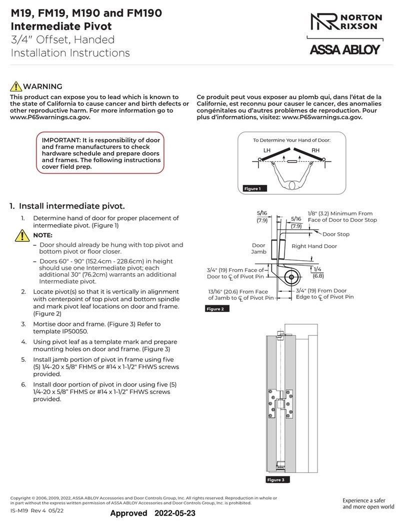
Assa Abloy NORTON RIXSON M19 installation instructions
Cal-Royal
Cal-Royal CRCODE-203 Instruction and programming manual
