manuals.online logo
Brands
  1. Home
  2. •
  3. Brands
  4. •
  5. Gate House
  6. •
  7. Door Lock
  8. •
  9. Gate House TS700 User manual

Gate House TS700 User manual

B. DRILL HOLES
Drill 2-1/8 in. (54 mm) hole through door face.
It is recommended that the hole should be drilled from both sides to
prevent splitting.
Drill 1 in. (25 mm) hole in center of door edge.
B. TALADRE LOS ORIFICIOS
Taladre un orificio de 5,4 cm (2-1/8”) a través del frente de la puerta.
Se recomienda que el orificio se taladre desde ambos lados para evitar
la formación de grietas.
Taladre un orificio de 2,5 cm (1”)
al centro del borde de la puerta.
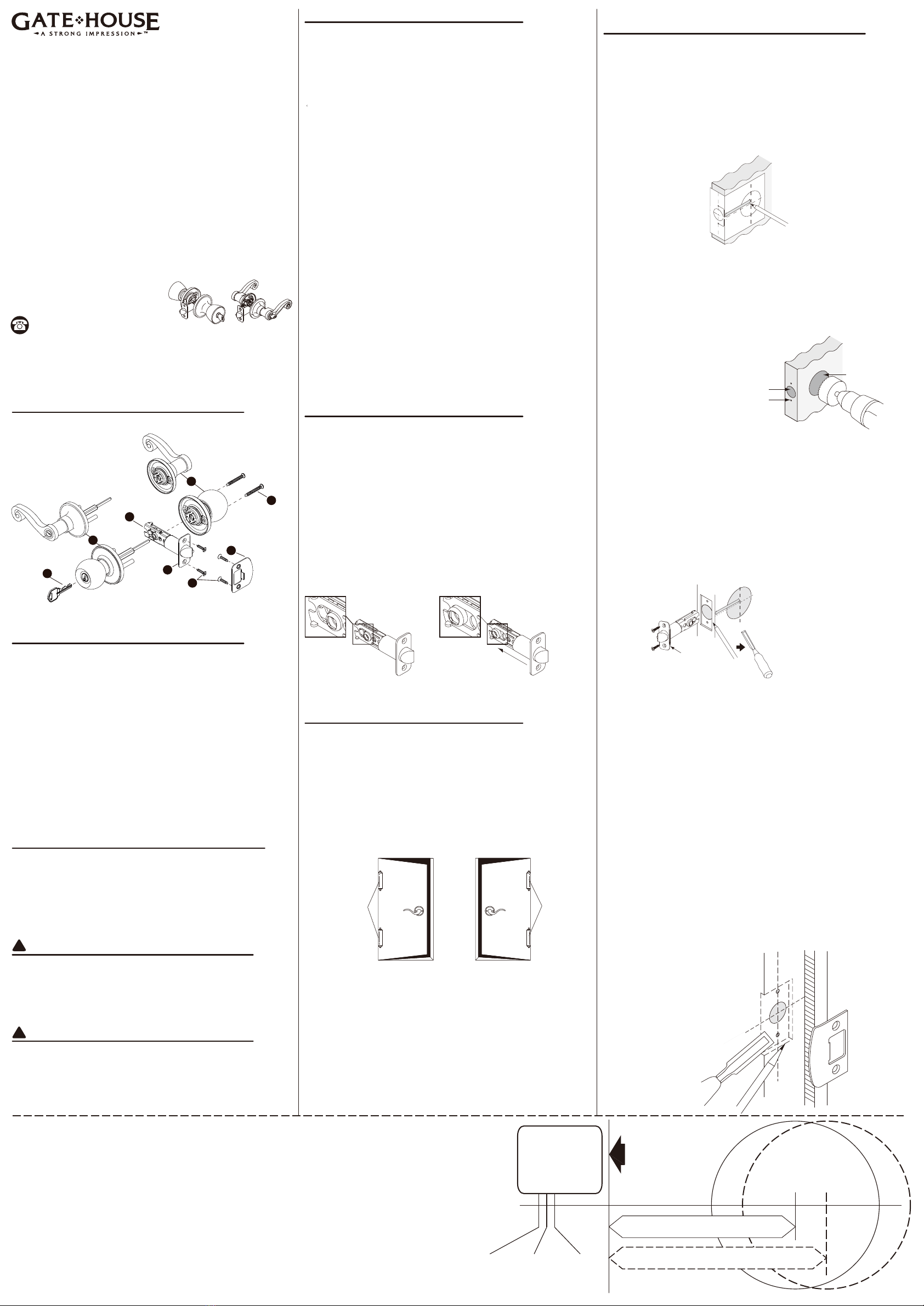
C. INSTALL LATCH
Insert latch in hole keeping latch parallel to door face.
Mark outline the area to be chiseled and remove the latch.
Chisel marked area to a depth of approximately 1/8 in. (3 mm)
or until latch face is flush with door edge.
Insert latch and install the 3/4 in. (19 mm) screw.
C. INSTALE EL PESTILLO
Inserte el pestillo en el orificio, manteniéndolo paralelo al frente de la puerta.
Marque el contorno cincelado y retire el pestillo.
Cincele el área marcada hasta una profundidad de aproximadamente
3 mm (1/8”) de profundidad o hasta que el frente del pestillo quede
al ras del borde de la puerta.
Inserte el pestillo e instale los tornillos de 1,9 cm (3/4”).
SAFETY INFORMATION/INFORMACIÓN DE SEGURIDAD
Please read and understand this entire manual before attempting to assemble,
operate or install the product.
Lea y comprenda completamente este manual antes de intentar ensamblar,
usar o instalar el producto.
PREPARATION/PREPARACIÓN
Before beginning installation of product, make sure all parts are present.
Compare parts with package contents list and hardware contents list. If any
part is missing or damaged, do not attempt to assemble, install or operate
the product. Contact customer service for replacement parts.
ESTIMATED ASSEMBLY TIME: 20 - 30 MINUTES
TOOLS NEEDED FOR NEW INSTALLATION:
• Pencil
• Chisel
• Tape Measure
• Hammer
• Phillips Screwdriver
• 1 in. and 1/8 in. Drill Bits
• 2-1/8 in. Hole Boring Bit
• Power Drill
Installation illustrations are shown with ENTRY models. Procedure is
identical for Entry, Privacy, and Passage Models in any knob/lever design.
Antes de comenzar a instalar el producto, asegúrese de tener todas las piezas.
Compare las piezas con la lista del contenido del paquete y la de los
aditamentos. No intente ensamblar, instalar ni usar el producto si falta
alguna pieza o si éstas están dañadas. Póngase en contacto con el
Departamento de Servicio al Cliente para obtener piezas de repuesto.
TIEMPO ESTIMADO DE ENSAMBLAJE: 20 A 30 MINUTOS.
HERRAMIENTAS NECESARIAS PARA UNA INSTALACIÓN NUEVA:
• Lápiz
• Cincel
• Cinta métrica
• Martillo
• Destornillador Phillips
• Brocas para taladro de 1” y 1/8”
• Broca de precisión de 2-1/8”
• Taladro eléctrico
Las ilustraciones de la instalación se muestran con modelos de ENTRADA.
El procedimiento es idéntico para los modelos de entrada, privacidad
y pasaje en cualquier diseño de perilla/palanca.
!
!
1-3/4 in.
4,5 cm
(45 mm)
1-3/8 in.
3,5 cm
(35 mm)
1-9/16 in.
4 cm
(40 mm)
Ø 2-1/8 in. (54 mm)
Ø 5,4 cm (2-1/8”)
Fold here. Place on
door edge.
Doble aquí. Coloque
en el borde de la
puerta.
Backset 2-3/4 in. (70 mm)
Seguro de 7 cm (2-3/4”)
Backset 2-3/8 in. (60 mm)
Seguro de 6 cm (2-3/8”)
Drill 1 in. (25 mm)
hole at center of
door edge.
Taladre un orificio
de 2,5 cm (1”) al
centro del borde
de la puerta
PACKAGE CONTENTS/CONTENIDO DEL PAQUETE
HARDWARE CONTENTS/ADITAMENTOS
For replacement parts & troubleshooting, call customer service at
1-877-4GATEHS, 8:30 a.m. - 5:30 p.m., EST, Monday - Friday.
Para obtener piezas de repuesto e información sobre solución de
problemas, llame al Departamento de Servicio al Cliente al 1-877-4GATEHS,
de lunes a viernes de 8:30 a.m. a 5:30 p.m., hora estándar del Este.
REPLACEMENT PARTS LIST & TROUBLESHOOTING
LISTA DE PIEZAS DE REPUESTO y SOLUCIÓN DE PROBLEMAS
TCD-0000H19 10/12-00
BEFORE PROCEEDING/ANTES DE PROCEDER
A. Please read these instructions completely before attempting to install
lock.
B. Make sure backset of lock is same as backset of your door.
If an adjustable latch is to be used, please adjust the backset to fit your
door.
A. Lea estas instrucciones completamente antes de intentar instalar la cerradura.
B. Asegúrese de que el seguro de la cerradura es el mismo que el de la puerta.
Si se utilizará un pestillo ajustable, regule el seguro de manera que se adapte
a la puerta.
2-3/8 in. (60 mm)
6 cm (2-3/8”) 2-3/4 in. (70 mm)
7 cm (2-3/4”)
ADJUSTABLE LATCH FOR 2-3/8 in. (60 mm) AND 2-3/4 in. (70 mm)
BACKSET
PESTILLO AJUSTABLE PARA SEGUROS DE 6 cm (2-3/8”)
Y 7 cm (2-3/4”)
ITEM/ARTÍCULO #
0117977/0117993/0117987
0279812/0037249/0117976
0117992/0117985/0279811
0037642/0117973/0117991
0117984/0279797/0040485
0332603/0332593/0332591
0332594/0332592/0332589
0332595/0332598/0332596
0332611/0332597/0332599
KNOB/LEVER KEYED ENTRY
BED & BATH
HALL & CLOSET
PERILLA/PALANCA DE ENTRADA CON LLAVE
DORMITORIO Y BAÑO
SALA Y ARMARIO
MODEL/MODELO #
TS700/TS800/TS600
TFX700/TFX200/TS710
TS810/TS610/TFX710
TFX210/TS730/TS830
TS630/TFX730/TFX230
L6X200B/L6X700B/L6X201B
L6X701B/L6X203B/L6X703B
LAX200B/LAX700B/LAX201B
LAX701B/LAX203B/LAX703B
Key (2) (Only included in Entry Knob/Lever)
Outside Knob Assembly
Latch
Inside Knob/Lever Assembly
1-5/16 in. (33 mm) Mounting Screws (2)
Faceplate
3/4 in. (19 mm) Latch/Strike Plate Screws (4)
Strike Plate
A.
B.
C.
D.
E.
F.
G.
H.
Llaves (2) (sólo se incluyen en la perilla/Palanca de entrada)
Ensamble de perilla exterior
Pestillo
Ensamble de perilla/palanca interior
Tornillos de montaje (2) de 3,3 cm (1-5/16”)
Placa frontal
Tornillos del pestillo/placa del cerrojo (4) de 1,9 cm (3/4”)
Placa del cerrojo
A.
B.
C.
D.
E.
F.
G.
H.
1. DOOR DRILLING FOR NEW INSTRUCTION
1. TALADRADO DE LA PUERTA PARA UNA NUEVA INSTRUCCIÓN
A. MARK DOOR
Mark door edge approximately 36 in. (914 mm) from floor.
Fold template along fold line. Place center of template on marked position.
Mark center hole on template to door face; for 2-3/8 in. (60 mm) or
2-3/4 in. (70 mm) backset, mark center hole on template to door edge.
A. MARQUE LA PUERTA
Marque la puerta aproximadamente a 91,4 cm (36”) del suelo.
Doble la plantilla a lo largo de la línea de doblado. Coloque el centro de la
plantilla en la posición marcada.
Marque el orificio central de la plantilla en el frente de la puerta. Para seguros
de 6 cm (2-3/8”) o 7 cm (2-3/4”), marque el orificio central de la plantilla
en el borde de la puerta.
Hinges
Bisagras
Left hand door
Puerta hacia la izquierda
Right hand door
Puerta hacia la derecha
Hinges
Bisagras
Exterior
Exterior
DETERMINE HANDING OF YOUR DOOR
DETERMINE LA COLOCACIÓN DE LA PUERTA
Stand at exterior side and face the door.
A. Your door is a left hand door if hinges are installed at your left hand.
B. Your door is a right hand door if hinges are installed at your right
hand.
Coloque en el exterior enfrentando la puerta.
A. La puerta está orientada hacia la izquierda si las bisagras están
instaladas a la izquierda.
B. La puerta está hacia la derecha si las bisagras están instaladas
a la derecha.
D. INSTALL STRIKE
Insert end of template against flat of latch bolt and close door against stop.
Mark template from edge of jamb and locate strike opening.
Move 1/4 in. (6.5 mm) for plainlatch and 3/8 in. (9.5 mm) for deadlatch towards
door stop to locate center line for screws and 1 in. (25 mm) hole.
Drill 1 in. (25 mm) hole x 1/2 in. (12.5 mm) deep minimum in door jamb on center
line of screws.
Align screw holes on strike with center line on jamb.
Mark outline of strike and chisel 1/16 in. (1.5 mm) deep.
Install strike and 3/4 in. (19 mm) screws.
Note: If required bend Adjustable Tang on strike to eliminate loose fit between
door and door stop.
D. INSTALE EL CERRADERO
Inserte el extremo de la plantilla contra la parte plana del perno del pestillo
y cierre la puerta contra el tope.
Marque la plantilla desde el borde del marco interior para puerta y ubique la
abertura del cerradero.
Mueva hacia la puerta 0,65 cm (1/4”) para pestillos simples y 0,95 cm (3/8”)
para aldabas dormidas, a fin de ubicar la línea central para los tornillos y el
orificio de 2,5 cm (1”).
Taladre un orificio de 2,5 cm (1”) x 1,25 cm (1/2”) mínimo en la línea central
de tornillos del marco interior para puerta.
Alinee los orificios de los tornillos del cerradero con la línea central del marco
interior para puerta.
Marque el contorno del cerradero y cincele 1,5 mm (1/16”) de profundidad.
Instale el cerradero y los tornillos de 1,9 cm (3/4”).
Nota: De ser necesario, doble la espiga ajustable del cerradero para eliminar
el ajuste holgado entre la puerta y el tope de ésta.
1/8 in.
0,3 cm
(3 mm)
1 in.
2,5 cm
(25 mm)
2-1/8 in.
5,4 cm
(54 mm)
Call customer service at 1-877-4GATEHS,
8:30 a.m. - 5:30 p.m., EST, Monday - Friday.
Llame al Servicio al Cliente al 1-877-4GATEHS,
de lunes a viernes de 8:30 a.m. a 5:30 p.m.,
hora estándar del Este.
Questions/¿Preguntas?
ATTACH YOUR RECEIPT HERE
ADJUNTE SU RECIBO AQUÍ
Serial Number/Número de serie
___________________________
Purchase Date/Fecha de compra
___________________________
WARNING/ADVERTENCIA
IF DRILLING IS REQUIRED, you should read and thoroughly understand
all steps prior to drilling. Please drill holes from both sides to avoid
splintering of the door face.
SI SE DEBE TALADRAR, debe leer y comprender completamente todos los
pasos antes de proceder. Taladre orificios desde ambos lados para evitar
astillar el frente de la puerta.
Faceplate
Placa frontal Outline
Contorno
Chisel 1/8 in. (3 mm) deep
Cincel de 0,3 cm (1/8”)
de profundidad
A
B
C
D
E
F
G
H
Printed in Taiwan
Impreso en Taiwán
WARRANTY/GARANTÍA
Limited Lifetime Warranty
The Manufacturer extends a Limited Lifetime Mechanical and Finish Warranty to the original “User” of this Product against defects in materials and workmanship as long as the User occupies the residential premises upon
which the Product was originally installed. Upon return of a defective Product to the Manufacturer, the Manufacturer shall either replace, repair or refund the purchase price in exchange for the Product.
This warranty does not cover abused or misused Products or those Products used in commercial applications.
No other warranties, express or implied are made with respect to the Product including but not limited to any implied warranty of merchantability or fitness for a particular purpose.
The Manufacturer DOES NOT authorize any person to create for it any obligation or liability in connection with the Product.
The Manufacturer maximum liability hereunder limited to the purchase price of the Product, and in no event shall the company be liable for any consequential, indirect, incidental or special damages of any nature arising from
the sale or use of this Product, whether in contract, tort, strict liability or otherwise.
( For warranty service, please call 1-877-4GATEHS, 8:30 a.m. - 5:30 p.m. EST, Monday through Friday )
Note: Should the Product be considered a consumer product it may be covered by the Magnusson Moss Federal Warranty Act, please be advised that: (1) Some states do not allow limitations or incidental consequential
damages on how long an implied warranty lasts so that the above limitations may not fully apply: and (2) This warranty gives specific legal rights and a User may have other rights which may vary from state to state.
Garantía limitada de por vida
El fabricante extiende una garantía limitada de por vida, mecánica y del acabado, al “usuario” original de este producto, contra defectos de fabricación en el material y en la mano de obra mientras el usuario ocupe las
instalaciones residenciales en las que se instaló originalmente el producto. Cuando se devuelve un producto defectuoso al fabricante, éste deberá reemplazar, reparar o reembolsar el precio de compra a cambio del producto.
Esta garantía no cubre productos que hayan sufrido abuso o mal uso ni aquellos productos usados en aplicaciones comerciales.
No se otorgan otras garantías, expresas o implícitas, con respecto al producto, incluida, entre otras, cualquier garantía implícita de comerciabilidad o idoneidad para cualquier propósito determinado.
El fabricante NO autoriza a ninguna persona para crear una obligación o responsabilidad en conexión con el producto.
La máxima responsabilidad del fabricante según la presente se limita al precio de compra del producto y en ningún caso la empresa será responsable de ningún daño resultante, indirecto, accidental o especial de ninguna
naturaleza causado por la venta o uso de este producto, ya sea contractual, extracontractual, en estricta responsabilidad o de otra manera.
( Para servicio de garanía, llame al 1-877-4GATEHS, de lunes a viernes de 8:30 a.m. a 5:30 p.m., hora estándar del Este )
Nota: Si el producto se considera de consumo, es posible que esté cubierto por la ley federal de garantías Magnuson-Moss, por lo que debe tener presente que: (1) Algunos estados no permiten limitaciones ni daños
resultantes accidentales en cuanto a la duración de una garantía implícita, de modo que las limitaciones anteriores pueden no aplicarse completamente; y (2) esta garantía otorga derechos legales específicos y el usuario
podría tener también otros derechos que varían según el estado.
2. INSTALLATION OF LOCKSETS
2. INSTALACIÓN DE CERRADURAS
A. INSTALL EXTERIOR KNOB/LEVER
1. Press exterior knob/lever against exterior surface of the door making
certain the stems are positioned horizontally so they go through holes
in the latch case.
Note: The exterior knob/lever has no visible screws. If the door lock has
a key hole.
2. For knobset, make sure that the key hole is in a vertical position and the
"key teeth" are facing up.
3. For leverset, make sure that the key hole is in a horizontal position and
the "key teeth" are facing the lever.
A. INSTALE LA PERILLA/PALANCA EXTERIOR
1. Presione la perilla/palanca exterior contra la superficie exterior de
la puerta, asegurándose de que los vástagos estén en posición
horizontal, de manera que pasen por los orificios de la caja del pestillo.
Nota: La perilla/palanca exterior no tiene tornillos visibles. Si la
cerradura para puerta tiene un ojo de la cerradura.
2. En el caso del conjunto de perilla, asegúrese de que el ojo de la
cerradura se encuentra en posición vertical y que los “dientes de la
llave” apuntan hacia arriba.
3. En el caso del conjunto de palanca, asegúrese de que se encuentre
en posición horizontal y que los “dientes de la llave” apuntan hacia la
palanca.
B. INSTALL INTERIOR KNOB/LEVER
1. Install interior knob/lever by placing on spindle and aligning screw
holes with stems.
2. Push flush against the door.
Tighten screw near the door edge first, then tighten the other side until
lockset is firm.
Note: To have the proper leveling of lock knob/levers and to avoid
sagging after installation, check knob/lever fit
and orientation prior to installing and securely tightening the
mounting screws.
B. INSTALE LA PERILLA/PALANCA INTERIOR
1. Instale la perilla/palanca interior colocándola en el eje y alineando los
orificios de los tornillos con los vástagos.
2. Empuje hasta dejarla al ras de la puerta.
Primero, apriete el tornillo que está cerca del borde de la puerta, luego
apriete el del otro lado hasta que el cerrojo quede firme.
Nota: Para lograr un apalancamiento adecuado de la perilla/palanca de
la cerradura y así evitar el aflojamiento después de la instalación,
se sugiere revisar el ajuste y la orientación de la perilla/palanca,
antes de instalar y apretar firmemente los tornillos de montaje.
3. HOW TO CHANGE LEVER HANDING
3. CÓMO CAMBIAR LA COLOCACIÓN DE LA PALANCA
A. Insert key to unlock outside lever.
Rotate key to horizontal position and withdraw.
A. Inserte la llave para desbloquear la palanca exterior.
Gire la llave hasta dejarla en posición horizontal y retírela.
Catch tool
Pasador captador
Catch hole
Orificio de cierre
Catch hole
Orificio de cierre
Spindle
Eje
Slot on lever
Orificio de la palanca
Cylinder
Cilindro
Cylinder
Cilindro
Spindle
Eje
Pull
Tirador
Pull
Tirador
C. If cylinder is also removed from spindle, please insert it securely back
into the spindle.
C. Si también retira el cilindro del eje, vuelva a insertarlo firmemente en éste.
D. Swap levers. Insert lever over to spindle, and align slot on the lever shank
with catch hole on the rose and press until secure and full engagement
between lever and spindle is reached.
D. Intercambie las palancas. Inserte la palanca sobre el eje, alinee los orificios
taladrados del vástago de la palanca con el orificio de cierre en la elevación
y presione hasta que quede fijo y entre completamente entre la palanca y el
eje.
B. Insert catch tool into knob catch hole on the outside rose and pull outside
lever off spindle.
Repeat the same on the inside to remove inside lever.
(Note: Remove catch tool as you pull lever off.)
B. Inserte un pasador captador en el orificio de cierre de la perilla en la
elevación exterior y jale la palanca exterior hasta extraerla del eje.
Repita el mismo procedimiento en el interior para retirar la palanca interior.
(Nota: Retire el pasador captador del orificio de cierre
de la perilla al extraer la palanca.)
CARE AND MAINTENANCE/CUIDADO Y MANTENIMIENTO
THE FOLLOWING CARE INSTRUCTIONS SHOULD
BE FOLLOWED TO ENSURE A LONG LASTING FINISH:
1. Remove locks, or do not install locks, prior to painting you door.
2. Periodically clean with mild soap and a soft cloth only.
Do not use abrasives or harsh chemicals and avoid sharp objects.
SE DEBEN SEGUIR LAS SIGUIENTES INSTRUCCIONES
DE CUIDADO PARA ASEGURAR UN ACABADO DURADERO:
1. Retire todas las cerraduras o no las instale antes
de pintar la puerta.
2. Limpie periódicamente sólo con jabón y un paño suave.
No use agentes químicos abrasivos y evite los objetos afilados.

This manual suits for next models

53

Other Gate House Door Lock manuals

Gate House GCX2D01 User manual

Gate House

Gate House GCX2D01 User manual

Gate House HY77F1B User manual

Gate House

Gate House HY77F1B User manual

Gate House G2X2D01 User manual

Gate House

Gate House G2X2D01 User manual

Popular Door Lock manuals by other brands

Assa Abloy R10 installation guide

Assa Abloy

Assa Abloy R10 installation guide

Assa Abloy Aperio C100 V3 Installation and mounting instructions

Assa Abloy

Assa Abloy Aperio C100 V3 Installation and mounting instructions

Lockly DEADBOLT EDITION 7S installation manual

Lockly

Lockly DEADBOLT EDITION 7S installation manual

Kwikset WEISER Tavaris 800TVH LIP 26 SMT installation guide

Kwikset

Kwikset WEISER Tavaris 800TVH LIP 26 SMT installation guide

Iseo Electa Perfecta 990850 Assembling instructions

Iseo

Iseo Electa Perfecta 990850 Assembling instructions

PERCo LB-72.4 Operation manual

PERCo

PERCo LB-72.4 Operation manual

Assa Abloy Corbin Russwin ED5800 Series installation instructions

Assa Abloy

Assa Abloy Corbin Russwin ED5800 Series installation instructions

Samsung SHS-H625 user manual

Samsung

Samsung SHS-H625 user manual

eSSL TL200 Installation instruction

eSSL

eSSL TL200 Installation instruction

Simons Voss Technologies SREL quick guide

Simons Voss Technologies

Simons Voss Technologies SREL quick guide

Assa Abloy Corbin Russwin SE LP10 Series installation instructions

Assa Abloy

Assa Abloy Corbin Russwin SE LP10 Series installation instructions

Motorline professional M1805-X User& installer's manual

Motorline professional

Motorline professional M1805-X User& installer's manual

Scilox BL100 installation guide

Scilox

Scilox BL100 installation guide

Proxess PX10110003 Service manual

Proxess

Proxess PX10110003 Service manual

GATEMASTER SUPERLOCK DIGITAL SINGLE SIDED quick start guide

GATEMASTER

GATEMASTER SUPERLOCK DIGITAL SINGLE SIDED quick start guide

Schlage Touch FE695 Lever installation instructions

Schlage

Schlage Touch FE695 Lever installation instructions

latch M Series installation guide

latch

latch M Series installation guide

Assa Abloy Corbin Russwin ED5200N Series installation instructions

Assa Abloy

Assa Abloy Corbin Russwin ED5200N Series installation instructions

manuals.online logo
manuals.online logoBrands
  • About & Mission
  • Contact us
  • Privacy Policy
  • Terms and Conditions

Copyright 2025 Manuals.Online. All Rights Reserved.