Trinity E3000 Series User manual

E3000 – Operational Manual
TRINITY
[1]
USER’S MANUAL
USER’S MANUALUSER’S MANUAL
USER’S MANUAL
E3000
E3000E3000
E3000
Revenue Meters
Revenue MetersRevenue Meters
Revenue Meters
This document contains the latest technical information about E3000 which is a
micro-controller based Revenue Meter. The unit is tested against latest "MTE"
Standard Model PRS400.3 having basic accuracy of 0.02%, and is also traceable to
International Standards derived using appropriate ratio techniques.
The product, E3000 is sophisticated electronic equipment, and the user is advised to
read this User’s Manual carefully before attempting to install or operate the
equipment.
Published on:- 25th OCT’ 2011
Document Version: 1.0

E3000 – Operational Manual
TRINITY
[2]
Warranty statement
Warranty statementWarranty statement
Warranty statement
Trinity warrants to the original retail purchaser of the Trinity product enclosed with this
limited warranty statement that the product, if purchased new and used in the India
conforms to the manufacturer’s specifications and will be free from defects in
workmanship and materials for a period of one year from the date of original
purchase, unless expressly stated otherwise by Trinity, in a written format.
Should your Trinity product prove defective during the warranty period, please bring
the product securely packaged in its original container or an equivalent, along with
proof of the date of original purchase, to our Trinity Dealer or Factory. You are
responsible for all costs (shipping, insurance, travel time) in getting the product to the
service location. Trinity will, at its option, repair or replace on an exchange basis the
defective unit, without charge for parts or labor. When warranty service involves the
exchange of the product or of a part, the item replaced becomes Trinity property. The
replacement unit may be new or refurbished to the Trinity standard of quality, and at
Trinity’s option, the replacement may be another model of like kind and quality.
Trinity’s liability for replacement of the covered product will not exceed the original
retail selling price of the covered product. Exchange or replacement products or parts
assume the remaining warranty period of the product covered by this limited warranty.
What This Warranty Does Not Cover:
This warranty does not apply to refurbished or reconditioned products. This warranty
covers only normal use in India. This warranty does not cover damage to the Trinity
product caused by parts or supplies not manufactured, distributed or certified by
Trinity. This warranty is not transferable. This warranty does not cover third party
parts, components or peripheral devices added to the Trinity product after its
shipment from Trinity. Trinity is not responsible for warranty service should the Trinity
label or logo or the rating label or serial number be removed or should the product fail
to be properly maintained or fail to function properly as a result of misuse, abuse,
improper installation, neglect, improper shipping, damage caused by disasters such
as fire, flood, and lightning, improper electrical current, interaction with non-Trinity
products, or service other than by an Trinity Authorized Service.
The warranty and remedy provided above are exclusive and in lieu of all other
express or implied warranties including, but not limited to, the implied
warranties of merchantability or fitness for a particular purpose. In the event,
the remedies above fail, Trinity’s entire liability shall be limited to a refund of
the price paid for the Trinity product covered by this limited warranty. Except
as provided in this written warranty, neither Trinity Energy Systems Pvt. Ltd.
nor its affiliates shall be liable for any loss, inconvenience, or damage,
including direct, special, incidental, or consequential damages, resulting from
the use or inability to use the Trinity product, whether resulting from breach of
warranty or any other legal theory.
E3000 – Operational Manual
TRINITY
[3]
Contents
ContentsContents
Contents
Introduction .............................................................................................................. 4
The Main Features of the unit ............................................................................. 4
Technical Specifications...................................................................................... 5
Installation and Commissioning ............................................................................. 6
RS485 Connection .............................................................................................. 7
Remote Display Connection................................................................................ 8
Operational Details................................................................................................... 9
Programming Mode ................................................................................................ 9
Setting Unit Address ......................................................................................... 10
Setting EB TRIP LIMIT, TRIP DELAY and TRIP OFF TIME on KW.................. 10
Setting DG TRIP LIMIT on KW, TRIP DELAY and TRIP OFF TIME ................. 11
Setting Time and Date with RTC....................................................................... 12
Resetting Energies............................................................................................ 12
Resetting Maximum Demand ............................................................................ 13
Run Mode ............................................................................................................. 14
Communication ...................................................................................................... 19
Modbus RTU on RS 485 Port............................................................................ 19
Appendix................................................................................................................. 20

E3000 – Operational Manual
TRINITY
[4]
Introduction
IntroductionIntroduction
Introduction
The digital energy meter E3000 is a micro-controller based unit which not only
measures a host of electrical parameters to display them on a customized segment
LCD with white backlit, but also acts as a comprehensive load control device due to
its three numbers of internal latching relay contacts. These latching relays will cut
load when either load exceeds KW limit or force tripped from RS485. In addition to
this flexibility in terms of load control, the meter also has two serial ports. Both port
follows RS485 medium. One port is for EMS/SCADA and second for Remote Display
Unit. RS485 supports MODBUS RTU protocol for connections to EMS/SCADA.
The unit is meant for use in three phase four wire systems with Active Power (KW)
control. The meter address, tripping parameters, resetting the energy, date & time in
RTC are site programmable.
E3000 has dual source input. So when 230Volt AC input applied at dual source
input, then meter will register DG Energy.
The Main eatures of the unit
The Main eatures of the unitThe Main eatures of the unit
The Main eatures of the unit
Displays more than 20 Parameters.
Demand and Maximum Demand for both KW and KVA including date and
time of maximum demand occurrence.
Measurements of Individual voltage, current and PF in three phases.
Measurements of Energies, system PF, Powers and frequency.
Internal latching relays for Active Power (KW) control with trip limit and time.
RS-485 MODBUS-RTU connectivity with field programmable meter address.
Forcefully latching relays on/off on RS485 communication using EMS.
Customized Segment LCD with white backlight.

E3000 – Operational Manual
TRINITY
[5]
Technical Specifications
Technical SpecificationsTechnical Specifications
Technical Specifications
Parameters
Type Name Statistics
INPUT
Three Phases and Neutral of a 3P4W system
Voltage Direct Voltage Input : Up to 300V L-N, 50-60 Hz.
Current Whole Current Meter with up to 60A rating
Power Supply Auxiliary Supply: Not Needed
OUTPUT
Latching Relay
Three.
One on Each Phase.
CONTACT: 60A, 250VAC
MEASUREMENT
True RMS Basic
Parameters
Voltage
(Volts L-N) VL-N Accuracy : 0.5% of Reading
Current
(Amps IR, IY, IB) Accuracy : 0.25% of Reading
Line Frequency 45 to 55 Hz, Accuracy : 0.3% of Reading
Power
Active Power (P) Accuracy : 0.5% of Reading
(For IPFI>0.5)
Reactive Power (Q) Accuracy : 1.0% of Reading
(Between 0.5 Lag to 0.8 Lead)
Apparent Power (S) Accuracy : 0.5% of Reading
Power Factor Accuracy : 0.5% of Reading (IPFI≥0.5)
Range of Reading : 0.05 to 1.00 Lag/Lead
Energy
Total Active Energy
(KWH) Accuracy : 0.5 of Reading
Total Apparent Energy
(KVAH) Accuracy : 0.5% of Reading
Total Reactive Energy
(KVARH) Accuracy : 1.0% of Reading
Demand
Active Power (KW) Demand – 30-Minute Fixed Window
Apparent Power (KVA) Demand - 30-Minute Fixed Window

E3000 – Operational Manual
TRINITY
[6]
Installation and Commissioning
Installation and CommissioningInstallation and Commissioning
Installation and Commissioning
The unit supports only for 3P4W electrical installation and user is advised to read
carefully the instructions before installing and commissioning.
Follow the steps below to install and commission the unit
1. Push the unit into the panel and mount on the wall.
2. Connect the three phases with the phase sequence being R-Y-B to the
terminal marked, 1, 4 and 7. Connect the neutral wire to the terminal marked,
10. Make sure that the three phases coming to the meter come through the
control fused appropriate Amp rating. This will protect the electronic inside
from damage due to severe overvoltage or phase faults in the systems.

E3000 – Operational Manual
TRINITY
[7]
3. The three phases R, Y and B coming from load will connect to the terminals
marked 3, 6, and 9, and then connect the neutral wire to the terminal marked
10.
4. In case of DG, the two wires coming from the DG will connect to the terminals
marked 25 and 26(DP and DN) with a supply voltage of 150VAC to 270 VAC.
Now, switch on the three phase supply, then the unit will display power
receiving information such as TESPL, and then the unit comes to RUN mode
displaying KWH and increasing value in DG.
5. Firstly, the unit should be programmed for various programmable parameters
in the Programming Mode. For this, see ‘Operational Details’ in the next
section.
6. Now, the unit is ready for the Operation.
RS485 Connection
RS485 ConnectionRS485 Connection
RS485 Connection

E3000 – Operational Manual
TRINITY
[8]
Remote Display Connection
Remote Display ConnectionRemote Display Connection
Remote Display Connection

E3000 – Operational Manual
TRINITY
[9]
Operational Details
Operational DetailsOperational Details
Operational Details
The unit, E3000 is a versatile meter with the feature needed to implement with a
robust electrical system and can also be configured to suit for most electrical
revenue purpose. The unit is achieved by making as many parameters field
programmable, as much as possible. There are basically two modes of operation:
1. Programming Mode
2. Run Mode.
After supplying power (100 VAC to 440 VAC) to the three phases, the unit comes to
Run Mode by default after displaying power receiving information, TESPL such as
shown below.
Programming Mode
Programming ModeProgramming Mode
Programming Mode
The unit has various user interface programmable parameters and the Programming
Mode can also be easily interfaced by using the keys PROG, UP and DOWN. The
unit is designed with a fixed password protection,”1947”. The user will therefore
enter a password before entering into Programming Mode. Now, in Run Mode,
press PROG key for about 5 seconds and then, the password display will prompt
such shown below.
To enter the password, press PROG key again that will start blinking first digit as
zero and is also showing that the password can be entered. Now, press UP key to
set to 1; press PROG key to shift to second digit and enter 9 by pressing UP or
DOWN keys. Likewise, enter 4 and 7 also, and then press PROG key to enter into
Programming mode. In case, the password entered is wrong, the unit will show Error
(ERR) and return into Run mode. Enter again the exact password as steps before.
On other hand, the password prompt will return into Run Mode, unless the password
is entered for about 30 seconds. Or, if the unit is in Programming Mode and keys
are not operated for about 30 seconds, unit will return to Run Mode.

E3000 – Operational Manual
TRINITY
[10]
Setting Uni
Setting UniSetting Uni
Setting Unit Address
t Addresst Address
t Address
For RS485 communication, the Unit Address can be set from 1 to 255 with an inbuilt
and fixed baud rate of 9600.
There is also an option for user to cut power off forcefully using RS485. User can
connect the load using EMS or manually in last parameter, “FTRIP
FTRIPFTRIP
FTRIP
NO
NONO
NO/YS
YSYS
YS” of
Programming Mode which will prompt when user has forcefully tripped the
load/relays.
To set the Unit Address, proceed the following instructions.
1. After entering the password, the unit will enter into Programming Mode and
display first programmable parameter, UNIT ADDRESS such as shown
below.
2. Press PROG key. Immediately, the parameter will start blinking which shows
that the parameters can now be changed. Set the parameter by pressing UP
or DOWN keys and press PROG key again to confirm the setting. The
parameter blinked will also stop blinking.
3. To set for next parameter, press UP key and set as steps before. Otherwise,
press PROG key to return into Run mode or unit will automatically leave the
programming mode after 30 seconds if no keys are pressed.
Setting EB TRIP LIMIT, TRIP DELAY and TRIP O TIME on KW
Setting EB TRIP LIMIT, TRIP DELAY and TRIP O TIME on KWSetting EB TRIP LIMIT, TRIP DELAY and TRIP O TIME on KW
Setting EB TRIP LIMIT, TRIP DELAY and TRIP O TIME on KW
The unit has relay for tripping on KW limit with a settable value from 5KW to 60KW.
The TRIP DELAY is the time duration for which the relay will wait for setting time
duration before switching off. The TRIP DELAY is settable from 1 to 15 minutes.
TRIP OFF TIME is the time duration for which the load will be switched off with
selected time duration before switching on. This TRIP OFF TIME is settable from 2
to 60 minutes.
For example, the TRIP Parameters are set such that:
TRIP LIMIT – 25 KW
TRIP DELAY – 5 MINUTES
TRIP OFF TIME – 15 MINUTES.
The unit will check continuously for system KW value. If KW will exceed its limit say
30 KW then the unit will keep a watch on this value for next 5 minutes. If the value of
KW remains above 25 for this 5 Minutes then the unit will cut off the load by tripping
the relays off. This load will remain cut off from the mains till next 15 Minutes as set
in the TRIP OFF TIME parameter. After this duration the unit will again switch ON
the relays and load will be connected to mains. In this state the TRIP LED will

E3000 – Operational Manual
TRINITY
[11]
remain ON. If the value of KW will remain above its tripping limit only for 3 minutes
then in this particular case the trip action will not be performed and hence the load
will not be cut from the mains.
To set the trip parameters, proceed the following instructions.
1. After entering the password, the unit will enter into Programming Mode and
display first programmable parameter, UNIT ADDRESS. Press UP key to
enter into TRIP LIMIT such as shown below.
2. The digit 1 at the top of the left corner shows the trip parameter is for EB only.
Press PROG key. Immediately, the parameter will start blinking which shows
that the parameters can now be changed. Set the parameter by pressing UP
or DOWN keys and press PROG key again to confirm the setting. The
parameter blinked will also stop blinking. To set for next parameter, TRIP OFF
TIME, press UP key to display with the following display.
3. Now, set the TRIP TIME as steps before. And press UP key again to set the
next parameter, TRIP OFF TIME with the following display.
4. Now, set the TRIP OFF TIME as steps before. To set for next parameter,
press UP key and set as steps before. Otherwise, press PROG key to return
into Run mode.
Setting DG TRIP LIMIT on KW, TRIP DELAY and TRIP O TIME
Setting DG TRIP LIMIT on KW, TRIP DELAY and TRIP O TIMESetting DG TRIP LIMIT on KW, TRIP DELAY and TRIP O TIME
Setting DG TRIP LIMIT on KW, TRIP DELAY and TRIP O TIME
The DG TRIP parameters are also same as EB TRIP parameter and can be entered
by pressing UP key from the above EB tripping programmable parameters till the DG
TRIP parameter displays such as shown below.

E3000 – Operational Manual
TRINITY
[12]
The digit 2 at the top of the left corner shows the trip parameter is for DG only. Set
DG TRIP parameters such as TRIP LIMIIT, TRIP DELAY and TRIP OFF TIME as
same as EB TRIP parameters with the steps before.
Setting Time and Date with RTC
Setting Time and Date with RTCSetting Time and Date with RTC
Setting Time and Date with RTC
The Time and Date are RTC where the Time can be set with the format of hour,
minutes, seconds i.e., HH-MM-SS and the Date can be set with the format of date,
month and year. i.e, DD-MM-YY format.
To set Time and Date, proceed the following instructions.
1. After entering the password, the unit will enter into Programming Mode and
display first programmable parameter, UNIT ADDRESS. Press UP key till the
unit enters into TIME such as shown below.
2. Press PROG key. Immediately, HH will start blinking which shows that the
hour can now be changed. Set hour by pressing UP or DOWN keys and press
PROG key to confirm the setting which will now start blinking to MM. Press
UP key or DOWN key to set it, and then press PROG key to confirm the
minute setting that will blink to SS. Similarly, set second by pressing UP or
DOWN key and press PROG key to confirm the setting which will now stop
blinking. To set DATE, press UP key such as shown below.
3. Now, set DATE as steps before. And press UP key again to set the next
parameter. Otherwise, press PROG key to return into Run Mode.
Resetting Energies
Resetting EnergiesResetting Energies
Resetting Energies
The energies KWH, KVAH and KVARH can be reset to zero.

E3000 – Operational Manual
TRINITY
[13]
To reset Energies, proceed the following instructions.
1. After entering the password, the unit will enter into Programming Mode and
display first programmable parameter, UNIT ADDRESS. Press UP key till
Reset Energy displays such as shown below.
2. Press PROG key. Immediately, the parameter will start blinking which shows
that the parameters can now be changed. Reset the parameter to YES by
pressing UP or DOWN keys and press PROG key again to confirm the
setting. The parameter will also stop blinking. After the energy is reset the unit
will restart in RUN mode.
3. To set for next parameter, press UP key and set as steps before. Otherwise,
press PROG key to return into Run mode.
Resetting Maximum Demand
Resetting Maximum Demand Resetting Maximum Demand
Resetting Maximum Demand
The Maximum Demand KW, KVA can be reset to zeroes.
To reset Maximum Demand, proceed the following instructions.
1. After entering the password, the unit will enter into Programming Mode and
display first programmable parameter, UNIT ADDRESS. Press UP key till
MAXIMUM DEMAND displays such as shown below.
2. Press PROG key. Immediately, the parameter will start blinking which shows
that the parameters can now be changed. Reset the parameter to YES by
pressing UP or DOWN keys and press PROG key again to confirm the
setting. The parameter will also stop blinking and immediately the unit will
restart in RUN mode.

E3000 – Operational Manual
TRINITY
[14]
Run Mode
Run ModeRun Mode
Run Mode
In the run mode, the various parameters measured/calculated by the meter are
TRUE RMS values and displayed on different pages on a customized segment LCD.
Make sure that for your exact power analysis, all the programmable parameter has
been specified properly.
The pages auto-scroll by default and also the pages can be scrolled by pressing UP
or DOWN keys. For more convenience to analyze the parameters in Run mode
pages, the pages can be frozen by pressing PROG key. Subsequently, the
parameters will start blinking and will not change the current page unless and until
pressed by UP or DOWN keys. To unfreeze the pages, press PROG key again that
will stop blinking and then, the pages will start auto-scrolling. Each page is displayed
for 8 seconds.
Display Description
The first page shows Active Energy
(KWH). The numeral 1 at the top
page shows the energy is for EB.
The second page shows Active
Energy (KWH). The numeral 2 at the
top page shows KWH is for DG.
When connected to DG, KWH value
will show on this page.
The third page shows Reactive
Energy (KVARH). The numeral 1 at
the top page shows the unit is for EB.
The fourth page shows Reactive
Energy (KVARH). The numeral 2 at
the top page shows the Reactive
energy is for DG. When connected to
DG, KVARH will display.

E3000 – Operational Manual
TRINITY
[15]
The fifth page shows Apparent
Energy (KVAH). The numeral 1 at the
top page shows KVAH is for EB.
The sixth page shows Apparent
Energy (KVAH). The numeral 2 at the
top page shows the KVAH is for DG.
When the unit is connected to DG,
the KVAH value will display on this
page.
The seventh page shows R-Phase
Voltage. The numeral 1 at the top
page shows the voltage is R-Phase.
The eight page shows Y-Phase
Voltage. The numeral 2 at the top
page shows the voltage is Y-Phase.
The ninth page shows B-Phase
Voltage. The numeral 2 at the top
page shows the voltage is B-Phase.
The tenth page shows R-Phase
Current. The numeral 1 at the top
page shows the Current is R-Phase.
The eleventh page shows Y-Phase
Current. The numeral 2 at the top
page shows the Current is Y-Phase.

E3000 – Operational Manual
TRINITY
[16]
The twelfth page shows B-Phase
Current. The numeral 3 at the top
page shows the Current is B-Phase.
The thirteenth page shows R-Phase
PF with LAG side. The numeral 1 at
the top page shows the PF is R-
Phase. In case, the PF is on LEAD
side, -sign will indicate to all three
phases and system PF. e.g., -0.999.
The fourteenth page shows Y-Phase
PF with LAG side. The numeral 2 at
the top page shows the PF is Y-
Phase.
The fifteenth page shows B-Phase
PF with LAG side. The numeral 3 at
the top page shows PF is B-Phase.
The sixteenth pages shows system
PF with LAG side.
The seventeenth page shows system
Frequency (HZ).

E3000 – Operational Manual
TRINITY
[17]
The eighteenth page shows system
Active Power (KW).
The nineteenth page shows system
Reactive power (KVAR).
The twentieth page shows system
Apparent power (KVA).
The twenty-first page shows Rising
demand of KVA.
The rising demand calculation
method is based on fixed window
method for 30 minutes interval with
respect to internal RTC.
The twenty-second page shows
maximum Demand (MD) of KVA. The
MD will be logging when Rising
Demand is greater than last MD. The
unit reflects Date & Time of MD
occurrence.
The twenty-third page shows the time
for maximum demand occurrence of
KVA.
The twenty-fourth page shows the
date for Maximum Demand
occurrence of KVA.

E3000 – Operational Manual
TRINITY
[18]
The twenty-fifth page shows Rising
Demand of KW.
The twenty-sixth page shows
Maximum Demand of KW.
MD occurrence is same as KVA MD
occurrence mentioned before.
The twenty-seventh page shows the
time for Maximum Demand
occurrence of KW.
The twenty-eighth page shows the
date for Maximum Demand
occurrence of KW.
The twenty-ninth page shows the
time in RTC.
The thirtieth page shows the date in
RTC.

E3000 – Operational Manual
TRINITY
[19]
Communication
CommunicationCommunication
Communication
E3000 provide the industry standard RS-485 communication port. These options
make it possible for a user to select E3000 to provide power and energy information
into a variety of existing or new control systems and communication networks.
Modbus RTU on RS 485 Port
Modbus RTU on RS 485 PortModbus RTU on RS 485 Port
Modbus RTU on RS 485 Port
For connection to a PLC/SCADA software, E3000 supports an RS485 port with
MODBUS-RTU protocol support. The station id for every meter is site selectable. The
data which can be read using MODBUS query # 3 (Read Holding Registers) is
provided in an address map. See INDEX in last section.
Communication line parameters: 9600 /8/N/1.
The register map is described in Appendix. If illegal address is sent in query or host,
try to read more than 200 bytes of data in one query except message is generated.
The parameter’s name and address are also mentioned.
If an attempt is made to read from some address other than the valid addresses, the
exception response is sent.
EXCEPTION CODE
In the event that the query from the HOST has no communication error, but there is
some error in specifying the address of register to be read, the meter return in
exception message. The format of the exception message will be under:
Unit address 83 Exception code CRC CRC
Exception code can have only one value: 02
If the address is not a valid start address or host has requested more than 200 bytes
of the data, this code is return.

E3000 – Operational Manual
TRINITY
TRINITYTRINITY
TRINITY
[20]
Appendix
AppendixAppendix
Appendix
Sr. No. ADDRESS PARAMETER
1 40200 Vrms - R Phase
2 40202 Vrms - Y Phase
3 40204 Vrms - B Phase
4 40206 Irms - R Phase
5
40208
Irms
-
Y Phase
6 40210 Irms - B Phase
7
40212
PF
-
R Phase
8 40214 PF - Y Phase
9 40216 PF - B Phase
10 40218 System PF
11 40220 System KVA
12 40222 System KW
13 40224 System KVAR
14 40226 Frequency
15 40228 EB KWH
16 40230 EB KVARH
17 40232 EB KVAH
18
40234
DG KWH
19 40236 DG KVARH
20 40238 DG KVAH
21 40240 KW Demand
22
4024
2
Max KW Demand
23 40244 MD KW Year
24 40246 MD KW Month
25 40248 MD KW Date
26 40250 MD KW Hour
27 40252 MD KW Minutes
28 40254 MD KW Seconds
29 40256 KVA Demand
30 40258 Max KVA Demand
31 40260 MD KVA Year
32 40262 MD KVA Month
33 40264 MD KVA Date
34 40266 MD KVA Hour
35
40268
MD KVA Minutes
36 40270 MD KVA Seconds
37
40272
EB Trip Limit
38 40274 EB Trip Delay
39 40276 EB Off Time
40 40278 DG Trip Limit
This manual suits for next models
1
Table of contents
Other Trinity Measuring Instrument manuals

Trinity
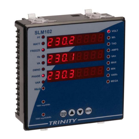
Trinity SLM102 User manual

Trinity
Trinity NF29 User manual

Trinity
Trinity INFINITY User manual

Trinity
Trinity XPERT-PRO User manual

Trinity
Trinity VAF User manual

Trinity
Trinity Olympus WS-811 User manual

Trinity
Trinity ENTITY User manual

Trinity
Trinity TINYPRO6 User manual

Trinity
Trinity TINYPRO3 User manual
Popular Measuring Instrument manuals by other brands

PCB Piezotronics
PCB Piezotronics 3713E11200G Installation and operating manual

Fluke
Fluke Series II Getting started guide

SCHUNK
SCHUNK FMS Assembly and operating manual

Spirax Sarco
Spirax Sarco VLM30 Installation and maintenance instructions

Emerson
Emerson Micro Motion 7835 installation manual

ICP DAS USA
ICP DAS USA PM-3033 Series user manual