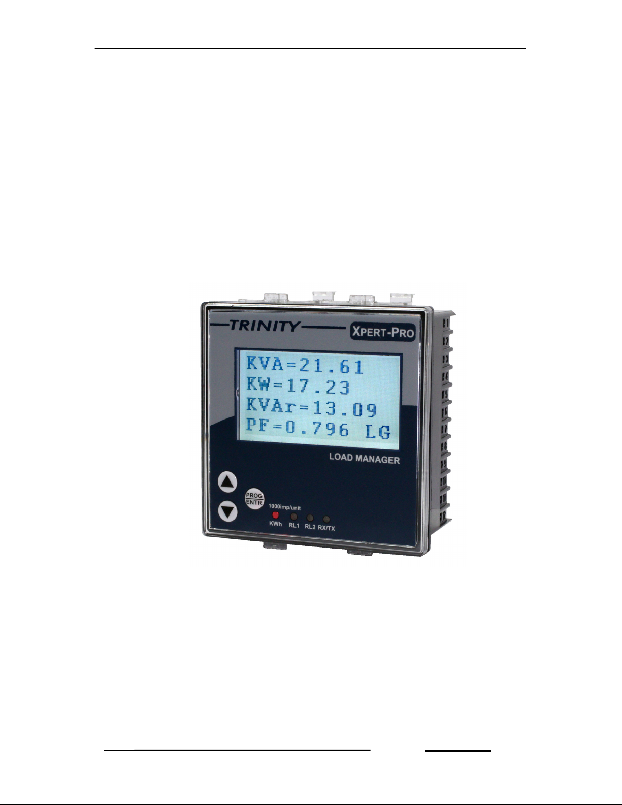
XPERT-PRO – Operational Manual
TRINITY
[2]
Warranty statement
Trinity warrants to the original retail purchaser of the Trinity product enclosed with this
limited warranty statement that the product, if purchased new and used in the India
conforms to the manufacturer’s specifications and will be free from defects in
workmanship and materials for a period of one year from the date of original
purchase, unless expressly stated otherwise by Trinity, in a written format.
Should your Trinity product prove defective during the warranty period, please bring
the product securely packaged in its original container or an equivalent, along with
proof of the date of original purchase, to our Trinity Dealer or Factory. You are
responsible for all costs (shipping, insurance, travel time) in getting the product to the
service location. Trinity will, at its option, repair or replace on an exchange basis the
defective unit, without charge for parts or labor. When warranty service involves the
exchange of the product or of a part, the item replaced becomes Trinity property. The
replacement unit may be new or refurbished to the Trinity standard of quality, and at
Trinity’s option, the replacement may be another model of like kind and quality.
Trinity’s liability for replacement of the covered product will not exceed the original
retail selling price of the covered product. Exchange or replacement products or parts
assume the remaining warranty period of the product covered by this limited warranty.
What This Warranty Does Not Cover:
This warranty does not apply to refurbished or reconditioned products. This warranty
covers only normal use in India. This warranty does not cover damage to the Trinity
product caused by parts or supplies not manufactured, distributed or certified by
Trinity. This warranty is not transferable. This warranty does not cover third party
parts, components or peripheral devices added to the Trinity product after its
shipment from Trinity. Trinity is not responsible for warranty service should the Trinity
label or logo or the rating label or serial number be removed or should the product fail
to be properly maintained or fail to function properly as a result of misuse, abuse,
improper installation, neglect, improper shipping, damage caused by disasters such
as fire, flood, and lightning, improper electrical current, interaction with non-Trinity
products, or service other than by an Trinity Authorized Service.
The warranty and remedy provided above are exclusive and in lieu of all other
express or implied warranties including, but not limited to, the implied
warranties of merchantability or fitness for a particular purpose. In the event,
the remedies above fail, Trinity’s entire liability shall be limited to a refund of
the price paid for the Trinity product covered by this limited warranty. Except
as provided in this written warranty, neither Trinity Energy Systems Pvt. Ltd.
nor its affiliates shall be liable for any loss, inconvenience, or damage,
including direct, special, incidental, or consequential damages, resulting from
the use or inability to use the Trinity product, whether resulting from breach of
warranty or any other legal theory.