Trinity TINYPRO3 User manual

Tinypro3 – Operational Manual
TRINITY
[1]
USER’S MANUAL
TINYPRO3
POWER METER
This document contains the latest technical information about TINYPRO3 which is a
micro-controller based Power meter. The product Infinity is sophisticated electronic
equipment, and the user is advised to read this User’s Manual carefully before
attempting to install or operate the equipment.
Published on: (mention the date of publishing)
Document Version: 1.0

TINYPRO3 – Operational Manual
TRINITY
[2]
Warranty statement
Trinity warrants to the original retail purchaser of the Trinity product enclosed with this
limited warranty statement that the product, if purchased new and used in the India
conforms to the manufacturer’s specifications and will be free from defects in
workmanship and materials for a period of one year from the date of original
purchase, unless expressly stated otherwise by Trinity, in a written format.
Should your Trinity product prove defective during the warranty period, please bring
the product securely packaged in its original container or an equivalent, along with
proof of the date of original purchase, to our Trinity Dealer or Factory. You are
responsible for all costs (shipping, insurance, travel time) in getting the product to the
service location. Trinity will, at its option, repair or replace on an exchange basis the
defective unit, without charge for parts or labor. When warranty service involves the
exchange of the product or of a part, the item replaced becomes Trinity property. The
replacement unit may be new or refurbished to the Trinity standard of quality, and at
Trinity’s option, the replacement may be another model of like kind and quality.
Trinity’s liability for replacement of the covered product will not exceed the original
retail selling price of the covered product. Exchange or replacement products or parts
assume the remaining warranty period of the product covered by this limited warranty.
What This Warranty Does Not Cover:
This warranty does not apply to refurbished or reconditioned products. This warranty
covers only normal use in India. This warranty does not cover damage to the Trinity
product caused by parts or supplies not manufactured, distributed or certified by
Trinity. This warranty is not transferable. This warranty does not cover third party
parts, components or peripheral devices added to the Trinity product after its
shipment from Trinity. Trinity is not responsible for warranty service should the Trinity
label or logo or the rating label or serial number be removed or should the product fail
to be properly maintained or fail to function properly as a result of misuse, abuse,
improper installation, neglect, improper shipping, damage caused by disasters such
as fire, flood, and lightning, improper electrical current, interaction with non-Trinity
products, or service other than by an Trinity Authorized Service.
The warranty and remedy provided above are exclusive and in lieu of all other
express or implied warranties including, but not limited to, the implied warranties of
merchantability or fitness for a particular purpose. In the event, the remedies above
fail, Trinity’s entire liability shall be limited to a refund of the price paid for the Trinity
product covered by this limited warranty. Except as provided in this written warranty,
neither Trinity Energy Systems Pvt. Ltd. nor its affiliates shall be liable for any loss,
inconvenience, or damage, including direct, special, incidental, or consequential
damages, resulting from the use or inability to use the Trinity product, whether
resulting from breach of warranty or any other legal theory.

TINYPRO3 – Operational Manual
TRINITY
[3]
Contents
Introduction ................................................................................................................4
The Main Features Available in This Model..........................................................4
Front View of the Unit ...........................................................................................4
Technical Specifications...........................................................................................5
Installation and Commissioning...............................................................................6
Connection Scheme..............................................................................................9
RS485 Connection..............................................................................................10
Operational Details ..................................................................................................11
Programming Mode................................................................................................12
Setting CT- primary.............................................................................................12
Setting a unit address for RS485 port.................................................................12
Run Mode ...............................................................................................................14
Run Mode Displays.............................................................................................14
Freezing and unfreezing the displays.................................................................15
Communication........................................................................................................16
Modbus RTU on RS485 Port..............................................................................16
Appendix.................................................................................................................17
Ordering Options......................................................................................................18

TINYPRO3 – Operational Manual
TRINITY
[4]
Introduction
Tinypro3 is a microcontroller based power meter which measures basic parameters
and displays on a red seven segment. Tinypro3 is a host of low cost, easy to use
individually that offers for the basic measurement capabilities required to monitor
electricity over and above basic metering. The unit can be installed to either 3P4W or
3P3W in an electrical installation and is able to measure parameters such as PF,
Active power (KW) and Active Energy (KWh).
The unit also has communication, RS485 port supporting MODBUS-RTU protocol for
integration with SCADA/EMS. The entire range is very rugged and cost-effective
solution. The unit is field proven and more than 100,000 units are active in service.
The Main Features Available in This Model
•Multi parameter Monitoring with LED indicators
•Displays with 0.4 Red Seven Segment
•Measurement of KW, PF and KWh.
•Modbus-RTU on RS485 port with SCADA/EMS
•All parameters with default accuracy class 1.0S
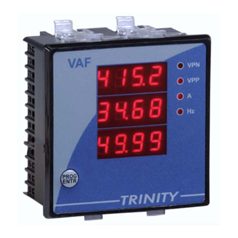
Front View of the Unit

TINYPRO3 – Operational Manual
TRINITY
[5]
Technical Specifications
* To be specified at the time of ordering along with PT primary.
SR.
NO
PARAMETERS
&
OPTIONS STATASTICS
1 Volts R-N Direct Voltage Input : Up to 300V L-N
Burden : 0.5VA
Secondary Voltage Input : 63.5V*
2 Volts Y-N
3 Volts B-N
4 Volts RY Direct Voltage Input : Up to 500V L-L
Burden : 0.5VA
Secondary Voltage Input : 110V*
5 Volts YB
6 Volts BR
7 Current R Secondary Current Input : 5A or 1A (To be specified at the
time of Ordering)
CT Primary : Site Selectable
Range of Reading : 5 – 5000A
Burden : < 1.0VA
Overload(Through CT) : 5A CT = 6A RMS Continuous
1A CT = 1.2A RMS Continuous
(Whole Current) : 120% of Imax continuous.
8 Current Y
9 Current B
10 KWh Range of Reading : 0 to 9999999.0 KWh
Accuracy : 1.0S as per IS13779.
11 System PF Accuracy : 1% of Reading (IPFI>0.5)
Range of Reading : 0.05 to 1.00 Lag/Lead
12 System KW Accuracy : 1.0% of Reading
(Between 0.5 Lag to 0.8 Lead)
13 DISPLAY 0.4” Red Seven Segment.
14 RS485 For Integration with EMS/SCADA
15 Bezel 96x96 mm DIN enclosure
16 Depth 55 mm

TINYPRO3 – Operational Manual
TRINITY
[6]
Installation and Commissioning
The unit can be used only for either 3P4W or 3P3W according to your ordering
option and requirement in your electrical installation.
To install and commission for 3P4W, proceed the following instructions:
1. Push the unit into the panel and mount using the claim provided on it.
2. Connect the auxiliary supply (80V AC to 270V AC) to the terminals marked P
and N.
3. Connect the three phases with the phase sequence being R-Y-B to the
terminals marked U1, U2 and U3 respectively. Make sure that the phases
coming to the unit come through control fuses of 1.0A rating. This will protect
the electronic inside from damage due to severe over voltage or phase faults
in the system.
4. Connect the neutral wire to the terminal marked U4.
5. Connect the two wires from the R-phase CT to the terminal marked M1 and
L1 such that S1 from CT goes to M1. Connect the two wires from the Y-phase
CT to the terminals marked M2 and L2 such that S1 from the CT goes to M2.
Connect the two wires from the B-phase CT to the terminals marked M3 and
L3 such that S1 from the CT goes to terminal marked M3.
6. Switch on the auxiliary supply as well as three phase supply and then, the unit
will come alive in order to display such as TRINITY ESPL, CT ratio, Unit
Address and Run Mode respectively.

TINYPRO3 – Operational Manual
TRINITY
[7]
7. Firstly, user should program the settable parameters, CT-primary and unit
address for RS485 communication port. (Refer Operational Details in the next
section).
8. Now the unit is ready for operation.

TINYPRO3 – Operational Manual
TRINITY
[8]
To install and commission for 3P3W, proceed the following instructions:
1. Push the unit into the panel and mount using the claim provided on it.
2. Connect the auxiliary supply (80V AC to 270V AC) to the terminals marked P
and N.
3. Connect the three phases with the phase sequence being R-Y-B to the
terminals marked U1, U4 and U3 respectively. Make sure that the phases
coming to the unit come through control fuses of 1.0A rating. This will protect
the electronic inside from damage due to severe over voltage or phase faults
in the system.
4. Connect the two wires from the R-phase CT to the terminals marked M1 and
L1 such that S1 from CT goes to M1. Connect the two wires from the B-phase
CT to the terminals marked M3 and L3 such that S1 from the CT goes to the
terminal marked M3.
5. Switch on the auxiliary supply as well as three phases supply and then, the
unit will come alive in order to display such as TRINITY ESPL, CT ratio, unit
Address and Run Mode respectively.
6. Firstly, user should program the settable parameters, CT-primary and unit
address for RS485 communication port as required. (Refer Operational
Details in the next section).
7. Now, the unit is ready for operation.

TINYPRO3 – Operational Manual
TRINITY
[9]
Connection Scheme

TINYPRO3 – Operational Manual
TRINITY
[10]
RS485 Connection

TINYPRO3 – Operational Manual
TRINITY
[11]
Operational Details
The Power Meter, TINYPRO3 is a versatile meter, with all the features needed to
implement for a robust electrical load management system. It can be configured to
monitor most electrical parameters and communication needs and, is also achieved
by making field programmable parameters, as possible.
There are basically two modes of operation in TINYPRO3:
1. Programming Mode
2. Run Mode
After supplying power (80 VAC - 270 VAC), the unit displays immediately power
receiving information, TRINITY ESPL on LCD screen and by default, the display
comes into Run Mode such as shown below.
Now, the unit can be operated by using the following keypad provided for both the
Programming Mode and Run Mode such as shown below.
Press key on Run Mode for about five seconds continuously, the unit will
therefore enter into Programming Mode, CT-PRIMARY with default value.

TINYPRO3 – Operational Manual
TRINITY
[12]
Programming Mode
In order to operate for all the field programmable parameters, it is easy for user
interface by pressing the keys such as, , and keys. Once the unit display
is in CT-PRIMARY, press key to move into the next programmable parameter,
UNIT ADDRESS for RS485 communication.
Setting CT- primary
The CT-primary is settable from 5 to 5000 and, should be set so as to give actual
current values in an electrical installation.
To set the CT-primary, proceed the following instruction:
1. Press key for about 4 to 5 seconds on Run Mode display.
2. The unit will alter into Programming Mode display with settable parameter,
CT-Primary such as shown below.
3. Press key. Immediately, “P” starts blinking with an interval of one second
which shows that the parameter is now settable. Set the CT-Primary by using
and keys until the desired value is received and then press key to
confirm the set value.
4. Now, the unit will reset and return into Run Mode.
Setting a unit address for RS485 port
The unit has the provision to specify a meter address at site for RS485 port. This
address can be set starting from 1 to 255 with a fixed baud rate of 9600.

TINYPRO3 – Operational Manual
TRINITY
[13]
To set the CT-Primary, proceed the following instruction:
1. Press key for about 4 to 5 seconds on Run Mode display.
2. The unit will alter into Programming Mode display with the settable parameter,
unit ADDRESS such as shown below.
3. Press key. Immediately, “P” starts blinking with an interval of one second
which shows that the parameter is now settable. Set the ADDRESS by using
and keys until the desired value is received and then, press key to
confirm the set value.
4. Now, the unit will reset and return into Run Mode.

TINYPRO3 – Operational Manual
TRINITY
[14]
Run Mode
In the run mode, the various parameters calculated by the TINYPRO3 are displayed
on different pages on a three lines of 0.4” Red Seven Segment. There are three
parameters which displays in different pages with the system values. Now the
displays can be altered and analyzed one by one.
Run Mode Displays
The Run Mode displays will autoscroll by default and stay for each page with an
interval of 7 to 8 seconds.
Page 1
The LED indicators glow on system PF and Active Power (KW) which shows their
values on first row and third row display respectively.
Page 2

TINYPRO3 – Operational Manual
TRINITY
[15]
The LED indicator glows on Total Active Energy (KWh) which shows its system
value on first row display.
Freezing and unfreezing the displays
The Run Mode Displays enable to freeze and unfreeze by pressing key, and then
the LED indicator will start blinking which shows that the display is frozen. By
pressing Sand Tkeys, the pages can also be changed and analyzed for each
parameter. To unfreeze the Run Mode, press key again which will stop blinking
the indicator and change the pages automatically in an interval of seven to eight
seconds.

TINYPRO3 – Operational Manual
TRINITY
[16]
Communication
UNIT CONNECTED TO RS485 PORT
The industrial standard RS-485 communication port option is also available in
TINYPRO3. This option makes it possible for a user to select TINYPRO3 to provide
power and energy information into a variety of existing or new control systems and
communication networks.
Modbus RTU on RS485 Port
In order to download live data for the various system parameters, user can use
RS485 connecting to a SCADA or EMS software. TINYPRO3 supports an RS485 port
with MODBUS-RTU support. The station id for every meter is site selectable, and so
is the baud rate. The data which can be read using MODBUS query # 3 (Read
Holding Registers) is provided in an address map, with the applicable multiplication
factors, vide Appendix.
Communication line parameters: 9600/8/N/1.
The register map is described in Appendix. All addresses are in decimal whose
parameters are unsigned long. If illegal address is sent in query or host, try to read
more than 32 bytes of data in one query except message is generated. The
parameters name, address and multiplication factor are also mentioned.
Reserved values are for future uses which are transmitted as zeroes. Please refer to
the address map for the various parameters in Appendix.

TINYPRO3 – Operational Manual
TRINITY
[17]
Appendix
3 phase
3000-3019 R phase
3030-3049 Y phase
3060-3079 B phase
3090-3109 MF
Reserved 3030-KWh Reserved Reserved X100
3002-KW Reserved Reserved Reserved X100
Reserved Reserved Reserved Reserved -
3006-PF Reserved Reserved Reserved X1000
Reserved Reserved Reserved Reserved -
DEFINING MULTIPLICATION FACTOR
•For providing resolution, all parameters except PT are multiplied with 100
before transmitting. Thus if the KW value is 278.99, it is sent out as 27899. PF
has MF of 1000, instead of 100. Thus, a PF value of 0.987 is sent as 987.
•If an attempt is made to read some address other than the valid addresses, the
exception response is sent.
EXPEPTION CODE
In the event that the query from the HOST has no communication error, but there is
some error in specifying the address of registers to be read, the meter returns an
exception message. The format of the exception message will be as under:
Unit Address 0X83 Exception code CRC CRC
Exception Code can have only one value, 03: if the address is not a valid, start
address or host has requested more than 32 bytes of data, this code is returned.

TINYPRO3 – Operational Manual
TRINITY
[18]
Ordering Options
TINYPRO3 can be ordered with the following options according to your requirements.
TINYPRO3
Power Meter
Technical
Specification Options
Installation 3P4W installation
3P3W installation
For H.T
application
( only if meter is to
be used for HT line)
PT-Primary…………..…KV.
PT-secondary…….…….V.
CT secondary
(Current) 5A
1A
Communication RS485 port with Modbus-RTU protocol.
None

TINYPRO3 – Operational Manual
TRINITY
[19]
P.O No. : …………………………………………………………………
Customer : …………………………………………………………………
Sr. No. : …………………………………………………………………
Routine and function tests conducted to relevant standards and our
Specifications/Literature/O & M Manual.
Traceability: tested against "MTE" Standard Model PRS400.3 having basic accuracy
of 0.02% traceable upto International Standards derived using appropriate ratio
techniques.
Result of Test : …………………………………………………………………
Remarks : …………………………………………………………………
Test engineer : …………………………………………………………………
Date : …………………………………………………………………
Table of contents
Other Trinity Measuring Instrument manuals

Trinity
Trinity VAF User manual

Trinity
Trinity TINYPRO6 User manual

Trinity
Trinity INFINITY User manual

Trinity
Trinity ENTITY User manual

Trinity
Trinity XPERT-PRO User manual

Trinity
Trinity Olympus WS-811 User manual

Trinity
Trinity NF29 User manual

Trinity
Trinity SLM102 User manual

Trinity
Trinity E3000 Series User manual
Popular Measuring Instrument manuals by other brands

PCE Health and Fitness
PCE Health and Fitness PCE-CT 25FN user manual

ETS-Lindgren
ETS-Lindgren HI-1501 user manual

PCB Piezotronics
PCB Piezotronics 3741E1210G Installation and operating manual

Badger Meter
Badger Meter ModMAG M Series user manual

Atlas Copco
Atlas Copco ACTA 3000 Guide to using

Avery Weigh-Tronix
Avery Weigh-Tronix evolution Series Service manual