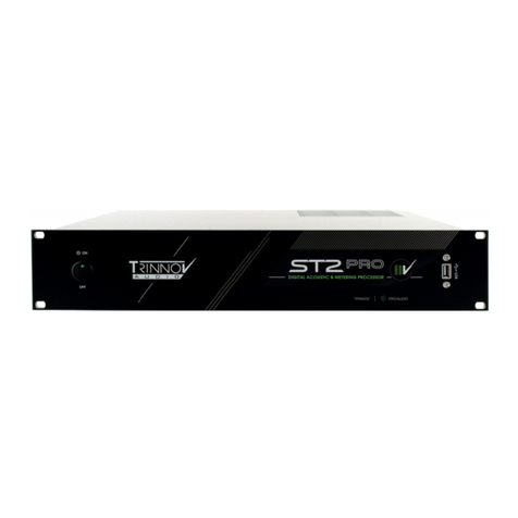
Trinnov Audio ST2 Pro User manual

ST2 Pro
www.trinnov.com
Quick Start
Version: 3.8.40 - December, 2020

2
ST2 PRO

Quick start
3
Thank you for choosing Trinnov.
Our goal is to create products that meet the monitoring requirements of the most demanding
audio professionals.
Our solutions enable them to produce the highest quality sound possible for music, broadcast,
film, or any type of audio content.
This is a Quick start document for the Trinnov Audio ST2 Pro.
This guide includes the essential information you need to start using your device in your studio
setup. We will make sure to help you through every step of the setup process using your ST2
Pro as a room optimizer.
For more detailed information on this product, please refer to the Trinnov Audio ST2 Pro User
Manual.

4
ST2 PRO

Quick start
5
SUMMARY
1
INSERTING YOUR ST2 PRO IN PRE-EXISTING CONFIGURATION 7
1.1 You are using a mixing desk or a sound card (DAC) with analog outputs. 7
1.2 You are using sources with digital outputs. 8
4
MICROPHONE 18
2
ACCESSING THE INTERFACE 10
2.1 | Trinnov App (For macOS users) 10
2.2 | Using your browser 11
5
CALIBRATION 20
3
PRE-CALIBRATION 14
6
POST-CALIBRATION 23

6
ST2 PRO
SAFETY INSTRUCTIONS
1. Read the following instructions carefully. Save all instructions for future reference.
2. Follow all warnings and instructions.
3. TRINNOV Audio expressly forbids unauthorized modification of this equipment.
4. Using the unit in the following locations can result in a malfunction:
• In direct sunlight
• Locations of extreme temperature or humidity
• Excessively dusty or dirty locations
• Locations of excessive vibration
• Close to magnetic fields
5. Condensation can form on the inside of the apparatus if it is suddenly moved from a cold environment to a
warmer location. Before switching the unit on, it is recommended that the unit be allowed to reach room
temperature.
6. Clean only with a dry cloth. Do not use liquid solvent-based cleaners.
7. Do not cover of bloc ventilation slots or openings. Never push objects of any kind into ventilation slots on the
equipment casing.
8. Install in conformance with the manufacturer’s instructions.
9. Maximum permissible operating conditions: 0°C to 40°C, 20-65% relative humidity.
10. Protect the power chord from being walked on or pinched particularly at plugs, convenience receptacles, and
the point where they exit from the apparatus.
11. Always replace damaged fuses with the correct rating and type (T1A).
12. Unplug this apparatus during lightning storms or when unused for long periods of time.
13. Do not open the equipment case. There are no user serviceable parts in this equipment. Refer all servicing to
qualified service personnel.
14. Please connect the designated AC/AC power supply to an AC outlet of the correct voltage. Do not connect it to
an AC outlet of voltage other than that for which your unit is intended.
TO COMPLETELY DISCONNECT THIS APPARATUS FROM THE AC MAINS, DISCONNECT THE POWER
SUPPLY CORD PLUG FROM THE AC RECEPTACLE.
THIS SYMBOL IS INTENDED TO ALERT THE USER TO THE PRESENCE OF UNINSULATED
‘DANGEROUS VOLTAGE’ WITHIN THE PRODUCT’S ENCLOSURE THAT MAY BE SUFFICIENT MAGNITUDE
TO CONSTITUTE A RISK OF ELECTRIC SHOCK.

Quick start
7
1 | SETTING UP YOUR ST2 PRO IN A
PRE-EXISTING CONFIGURATION
1.1 | YOU ARE USING A MIXING DESK OR A SOUND CARD (DAC)
WITH ANALOG OUTPUTS
If in the analog domain (meaning using analog sources from your sound card
or digital audio converters):
The most important thing is to put the ST2 Pro at the end of the chain.
IN
OUT
GPIO 1-8ANA. INPUTS
DIG. INPUTS
ANA. OUTPUTSDIG. OUTPUTS
WORD
CLOCK
21
2
1
1 2
3
3
4
4
1
ON
OFF
Active speakers Analog or Digital
Master Clock
Sound card Out Analog or Digital
3D Mic In for calibration only
ON
OFF
QUICK SETUP
Pair one Pair two
If you are using a monitor controller in your setup, start by plugging it to the ST2 Pro. In this
example, we will be using a DB-25 breakout cable from the controller to the Analog inputs 1
and 2 of the ST2 Pro.

8
ST2 PRO
IN
OUT
GPIO 1-8ANA. INPUTS
DIG. INPUTS
ANA. OUTPUTSDIG. OUTPUTS
WORD
CLOCK
21
2
1
1 2
3
3
4
4
1
ON
OFF
L AUX INPUT R INPUT OUTPUT DC IN TB REMOTE SLATE CUE AMP OUT REMOTE
Figure 1: Using a monitor controller
Then, make sure to plug the speakers to the ST2 Pro. Take the two cables that feed your main
Left and Right speakers and plug them into the analog outputs 1 and 2 to the ST2 Pro.
IN
OUT
GPIO 1-8ANA. INPUTS
DIG. INPUTS
ANA. OUTPUTSDIG. OUTPUTS
WORD
CLOCK
21
2
1
1 2
3
3
4
4
1
ON
OFF
L AUX INPUT R INPUT OUTPUT DC IN TB REMOTE SLATE CUE AMP OUT REMOTE
Figure 2: Plugging the speakers to the ST2 Pro
This wiring will work with any other monitoring controller (Avocet, SPL, …) and even controller
outputs from a console (SSL, Neve, …).
1.2 | YOU ARE USING SOURCES WITH DIGITAL OUTPUTS
If in the digital domain (meaning you have your own set of digital audio
converters or use loudspeakers with digital inputs):
Insert the ST2 Pro as an AES insert or directly output to your speakers through AES if they
have a digital input. If so, ensure that the system clock and synchronization parameters are
correctly set (see user manual for more information).
IN
OUT
GPIO 1-8ANA. INPUTS
DIG. INPUTS
ANA. OUTPUTSDIG. OUTPUTS
WORD
CLOCK
21
2
1
1 2
3
3
4
4
1
ON
OFF
L AUX INPUT R INPUT OUTPUT DC IN TB REMOTE SLATE CUE AMP OUT REMOTE
Figure 3: Using digital io

Quick start
9
Don’t forget to plug the AC power cord to the ST2 Pro and a network connection into your router
to use the Trinnov Mac App and control the ST2 Pro over the network. For more information,
you can refer to the Trinnov App section of the Quickstart.
On the left side of the ST2 Pro, a VGA and/or HDMI port are available for video monitors*as
well as USB inputs for keyboard and mouse to control the ST2 Pro directly.
Important Note: Make sure to remove any USB stick plugged in the ST2 Pro during the boot sequence.
IN
OUT
GPIO 1-8ANA. INPUTS
DIG. INPUTS
ANA. OUTPUTSDIG. OUTPUTS
WORD
CLOCK
21
2
1
1 2
3
3
4
4
1
ON
OFF
L AUX INPUT R INPUT OUTPUT DC IN TB REMOTE SLATE CUE AMP OUT REMOTE
Figure 4: The motherboard part of the device
Once you have everything plugged in (including AC power), you need to turn on the power
switch on the back panel of the ST2 Pro and engage the booting switch on the front panel of
the ST2 Pro.
* May differ depending on the generation of ST2 Pro.

10
ST2 PRO
2 | ACCESSING THE INTERFACE
The ST2 Pro is now online and connected to the internet. No need to configure
your network settings as they are set as Automatic DHCP (by default).
In order to connect to the interface, there are a few possibilities.
Ensure both of your devices (ST2 Pro + Windows/ Android/ ...) are on the
same network before proceeding.
2.1 | TRINNOV APP (FOR MACOS USERS)
The most straightforward way is to use the Trinnov App.*
After downloading the Trinnov App, you can launch it directly on your Mac.
The first thing that will appear is a small interface. This interface contains the basic monitoring
parameters needed.
These features are as follows:
- Volume change per 1dB steps.
- Mute: Mutes all audio outputs
- Dim: Decreases the volume by 20dB (by default)
- Optimizer: Tick to have the Optimizer ON/
Untick to have it bypassed.
Some useful information is also displayed:
- Active preset
- Sampling rate
- Clock mode
- Clock status
* Please visit the Trinnov website to download the latest version of the software. www.trinnov.com/support/
Figure 5: The Trinnov App

Quick start
11
The unit’s ID connected to the interface, and its current software version is located at the bottom.
In order to access the Optimizer settings, hit the Icon located at the bottom right of the app.
To get information about using the Optimizer settings, please refer to the Chapter 3 of this
Quickstart manual.
2.2 | LOCATING YOUR ST2 PRO IP ADDRESS
Each ST2 Pro processor includes a dedicated web server and, therefore, the
GUI can be accessed from a networked device with a web browser interface
such as a desktop computer, laptop, smartphone, tablet, etc.
If both your computer and ST2 Pro are connected on the same network, you can access the
interface through your web browser (Chrome preferred). It requires is to have your ST2 Pro
updated to its latest software release.
Date : December, 2020 Version: 3.8.40
First, locate your ST2 Pro IP address.
There are 2 ways of achieving this:
• With a physical screen plugged to it.
You will require an external monitor, a keyboard, and a mouse.
Plug them all to the motherboard part of the ST2 Pro (see the previous chapter on setting
up your ST2 Pro). Go to the Network settings to get the IP address.
• If you have a “Trinnov Remote” plugged in, navigate up to the network page.
In your web browser address bar, type in “http://<ip>/vnc.html
Replace <ip> with the ST2 Pro address.
You are connected to the interface.
Note: Also, as a Mac user, your ST2 Pro will be automatically listed in the “network”. You can double-click on
the device, then, select “share screen”.

12
ST2 PRO
Figure 6: The password is the serial number of your device (Six-digit number)
available on the rear side sticker
.

Quick start
13
Figure 7: The network page of the interface

14
ST2 PRO
3 | PRE-CALIBRATION
Here, we will focus on the process needed to get your first measurements.
The first thing is to go to the Preset tab of the interface.
Figure 8: The Preset page of the interface
The most important thing here is to make sure that the Built-in Preset is loaded.
This preset has every parameter of the unit set to default.
It is preconfigured for a stereo analog in and out set-up, making it a good starting point for your
first calibration. It will also save time for the remaining part of the configuration.

Quick start
15
Next, go to the Optimizer settings and hit the Calibration tab at the bottom left of the screen.
Figure 9: The calibration page of the interface
This is the page where you will take your first measurements.
As you can see in the Calibrated column, No! Is marked in red. It simply means that no
measurement has been taken yet.

16
ST2 PRO
In order to do so, we need to configure it first.
Hit the Configure button.
Figure 10: Changing the microphone file
The important information displayed here is the Mic name option.
Each 3D measurement microphone has its own calibration file. If not present by default, that
file must be installed first on your device for the measurements to be accurate.
The Mic name option needs to match the serial number written on the body of the microphone.
That name needs to be selected in the Mic name option.

Quick start
17
If not present, the microphone file can be found on the USB stick provided with the microphone.
This USB stick can be inserted in any USB ports available on the ST2 Pro (Front/Back).
After inserting the USB stick into any of the USB ports, a new page will appear.
Figure 11: The USB pop-up message
The important option here is to select “Load microphone files from USB key”.
Then, choose the “Microphone_Files” directory and hit “OK”.
Now, any microphone profile that was on the USB stick has been loaded into the ST2 Pro. In
order for the machine to take it into account, you will need to reboot the unit first.
After reboot, go back to the previous screen. In the Mic name, you will see the microphone file
loaded from the USB stick. After doing so, press “OK”.
This will get you back to the main calibration screen.
You can also set your microphone as the default microphone for future calibrations.
Good news! You are now ready to take your first measurement.
But, wait! We need to prepare the microphone first.

18
ST2 PRO
4 |MICROPHONE
The 3D Trinnov microphone is quite unique. It has 4 capsules on it. On the
bottom, you can see a white push-button switch to turn the microphone On
and Off. When On, a red LED will light up, meaning that the microphone is On.
THREAD
MICROPHONE CABLE
Figure 11: The Trinnov 3D microphone
It is important that you only turn the microphone On when the interface tells you to do so. Turn it
Off right after your measurement. This will prevent any chance of damaging your speaker by
getting feedback through your system.
On the backside of the microphone, you can see the name and the serial number. It needs to
match the number that you’ve entered on the software with the USB stick.
Let’s start by plugging the multi-pin cable to the microphone. Take the 4 XLR and plug them
into the analog inputs of the ST2 Pro.
IN
OUT
GPIO 1-8ANA. INPUTS
DIG. INPUTS
ANA. OUTPUTSDIG. OUTPUTS
WORD
CLOCK
21
2
1
1 2
3
3
4
4
1
ON
OFF
L AUX INPUT R INPUT OUTPUT DC IN TB REMOTE SLATE CUE AMP OUT REMOTE
Figure 12: Plugging the 3D microphone to the ST2 Pro

Quick start
19
Make sure to unplug your controller (if any) on the analog inputs of the ST2 Pro.
The microphone is on a microphone stand and ready for usage.
A few things to verify before calibrating regarding the measurement microphone position:
• The microphone needs to be positioned facing the center between the left and right
speakers.
• The center of the microphone is the red LED, it needs to be set forward.
• The capsules need to be placed at about ear level, located where you would be mixing
(height/ distance from your ear to the wall).
• The L and R speakers should be physically set 30° each from the center of the
measurement (you will be able to see the results after the calibration. Please refer to the
post-calibration chapter).
After setting it up as accurately as possible, it is time to calibrate.

20
ST2 PRO
5 |CALIBRATION
The First thing to consider here is that the test signal could be very loud.
Before going any further, now is a good time to make sure the red LED of the microphone is
turned OFF.
To prevent this process from hurting your ears or speakers, take a look at the top of the interface
and reduce the volume of the ST2 Pro by pressing the “-” (minus) button. This is the volume
control in dB. Start by turning it down to -30dB. This is a good number to start with for most
systems.
If you ignore this step, a message on-screen will appear right before calibration warning you
that the overall volume is louder than average.
When ready, press on “Calibrate”.
You will then hear 3 consecutive bursts of sound going through the speaker one by one until
all the speakers in the system have been measured by our 3D microphone.
If the signal is too quiet, it will stay on the 1st loudspeaker. If so, you can gradually increase the
volume while hearing the test signal coming through the loudspeaker until it moves to the next
one. Then, cancel it and press calibrate again to get a correct measurement.
The most common warning messages are explained below:
“Crest factor too low for capsules (?)”
• Check the input meters in the Processor/Meters page.
If the Input level is null on at least one of the 4 channels, go back to the Optimizer
Settings/ Calibration page and stop the calibration.
• Make sure that the microphone input routing is correct.
• The microphone battery may be low.
• If so the red led at the front of the microphone indicates its level.
• The microphone and or cable could have been damaged.
“Unstable position for speaker”
• Someone may have moved during measurement.
• An obstacle between the microphone and any speakers can disturb the measurement.
• The bandwidth of one of the speakers may be too narrow.
• Too many strong reflections around the microphone environment disturb the impulse
response measurement.
“Unable to localize speaker”
• Dipole/bipole speakers provide more than one wave at the same time, which can cause issues.
• Several speakers chained, providing more than one wave at the same time.
Other manuals for ST2 Pro
1
Table of contents
Other Trinnov Audio Computer Hardware manuals
Popular Computer Hardware manuals by other brands

Pima
Pima ZEL508 installation instructions
ekwb
ekwb EK-XLC PREDATOR 240 installation manual
Cypress Semiconductor
Cypress Semiconductor PSoC CapSense CY8CKIT-031 Kit Guide
Portwell
Portwell WADE-8065 user manual
Extron electronics
Extron electronics Annotator 300 user guide

AJA
AJA KONA LHe Plus Installation and operation guide
Panasonic
Panasonic AW-HHD100N operating instructions
Fujitsu
Fujitsu PRIMERGY Tape Drv DAT72 user guide

Renesas
Renesas R8C/13 quick start guide

HP
HP Adaptive Rack Cooling System System installation guide
Thermalright
Thermalright Macho Zero manual
NXP Semiconductors
NXP Semiconductors QSG ADC1x13D+ECP3 DB quick start guide
