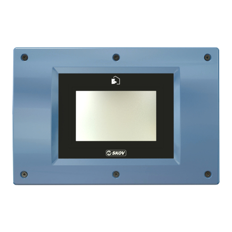
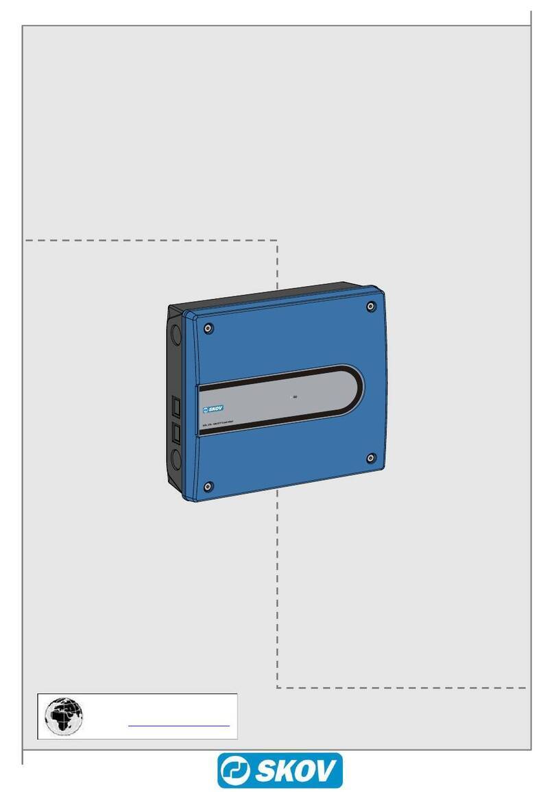
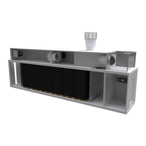
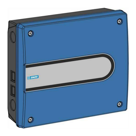
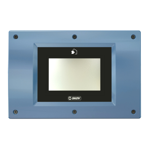
Skov DOL 532 Tunnel User manual

DOL 532 Tunnel
Climate
Technical Manual
612991 • 2023-05-31 Software version 8.0
English For other language variants of this document we refer to:
Español Para otras variantes del idioma de este documento, visite:
Français Pour les versions dans d'autres langues de ce document veuillez consulter:
http://docs.skov.com/1161


DOL 532 Tunnel
Technical Manual 3
Product and Documentation Changes
SKOV A/S reserves the right to change this document and the product herein described without further notice.
In case of doubt, please contact SKOV A/S.
The date of change appears from the front and back pages.
IMPORTANT
Notes concerning alarm systems
Breakdowns, malfunctions or faulty settings may cause substantial damage and financial losses when regulat-
ing and controlling the climate in a livestock house. It is therefore essential to install a separate, independent
alarm system that monitors the house climate concurrently with the climate and production controller. According
to EU-directive No. 98/58/EU, an alarm system must be installed in all mechanically ventilated houses.
We would like to draw your attention to the fact that the product liability clause of general terms and conditions
of sale and delivery specifies that an alarm system must be installed.
In case of an operating error or inappropriate use, ventilation systems can result in production
losses or cause loss of lives among livestock.
We recommend that ventilation systems should be mounted, operated and serviced only by
trained staff and that a separate emergency opening unit and an alarm system be installed as well
as maintained and tested at regular intervals, according to terms and conditions of sale and deliv-
ery.
Installation, servicing and troubleshooting of all electrical equipment must be carried out by quali-
fied personnel in compliance with the applicable national and international standard EN 60204-1
and any other EU standards that are applicable in Europe.
The installation of a power supply isolator is required for each motor and power supply to facilitate
voltage-free work on the electrical equipment. The power supply isolator is not included.
Note
• All rights belong to SKOV A/S. No part of this manual may be reproduced in any manner whatsoever without
the expressed written permission of SKOV A/S in each case.
• All reasonable efforts have been made to ensure the accuracy of the information contained in this manual.
Should any mistakes or imprecise information occur in spite of this, SKOV A/S would appreciate being noti-
fied thereof.
• Irrespective of the above, SKOV A/S shall not accept any liability with regard to loss or damage caused or
alleged to be caused by reliance on any information contained herein.
• Copyright by SKOV A/S.

DOL 532 Tunnel
Technical Manual
1 Product description ....................................................................................................................................... 6
2 Work routine ................................................................................................................................................... 7
3 Installation guide............................................................................................................................................ 8
3.1 Selecting components............................................................................................................... 8
3.2 Slave relays ................................................................................................................................ 8
3.3 Setup of operation form ............................................................................................................ 8
3.4 View week number..................................................................................................................... 9
3.5 Select type of Unit of measurements....................................................................................... 9
3.6 Connecting components........................................................................................................... 9
3.6.1 Installation wizard ........................................................................................................................ 9
3.6.2 The menu Show connection ...................................................................................................... 10
3.6.3 Manual I/O allocation ................................................................................................................. 10
3.6.4 Shared equipment...................................................................................................................... 11
3.7 Climate ...................................................................................................................................... 11
3.7.1 Air inlet ....................................................................................................................................... 11
3.7.2 Air outlet..................................................................................................................................... 11
3.7.2.1 Dynamic MultiStep ..................................................................................................................... 11
3.7.2.2 Setup of tunnel ventilation.......................................................................................................... 14
3.7.3 Heating....................................................................................................................................... 14
3.7.4 Setup of sensors ........................................................................................................................ 14
3.7.5 Active functions in the event of control failure............................................................................ 15
3.7.6 Set-up of tunnel cooling ............................................................................................................. 15
3.7.7 Stir fan........................................................................................................................................ 15
3.7.7.1 Control methods for stir fan........................................................................................................ 15
3.8 Production ................................................................................................................................ 16
3.8.1 Water ......................................................................................................................................... 16
3.8.2 24-hour clock ............................................................................................................................. 16
4 Calibration..................................................................................................................................................... 17
4.1 Calibration of Air Intake and Air Outlet.................................................................................. 17
4.1.1 Winch motor without feedback................................................................................................... 17
4.2 Calibration of climate sensors................................................................................................ 17
4.2.1 Calibration of Weather Station ................................................................................................... 17
4.2.2 Calibration of pressure sensor ................................................................................................... 18
4.2.3 Calibration of CO2 sensor (installed as CO2 sensor) ................................................................ 18
4.2.4 Calibration of NH3 sensor.......................................................................................................... 19
5 Testing........................................................................................................................................................... 20
5.1 Testing basis components...................................................................................................... 20
5.1.1 Testing temperature and air humidity sensors........................................................................... 20
5.1.2 Testing Alarm............................................................................................................................. 20
5.1.3 Testing emergency opening....................................................................................................... 20
5.2 Testing optional components: Manual control ..................................................................... 20
5.2.1 Testing climate functions ........................................................................................................... 21
5.2.1.1 Testing Air Intake and Air Outlet ................................................................................................ 21
5.2.1.2 Testing of Dynamic MultiStep .................................................................................................... 21
5.2.1.3 Stepless fans ............................................................................................................................. 22
5.2.1.4 MultiStep .................................................................................................................................... 22
5.2.1.5 Testing relay functions ............................................................................................................... 23
5.2.1.6 Emergency inlet ......................................................................................................................... 24
5.2.2 Testing production functions ...................................................................................................... 24
5.2.2.1 Testing relay for 24-hour clock................................................................................................... 24
5.3 Testing network connection ................................................................................................... 24
6 Service........................................................................................................................................................... 25
6.1 Settings..................................................................................................................................... 25

DOL 532 Tunnel
6.1.1 Climate....................................................................................................................................... 25
6.1.1.1 Setting exhaust units (MultiStep) ............................................................................................... 25
6.1.1.2 Fan settings ............................................................................................................................... 25
6.1.1.3 Setting outside temperature limit ............................................................................................... 26
6.1.1.4 Setting of heating ....................................................................................................................... 26
6.1.2 Production.................................................................................................................................. 26
6.1.3 Network settings ........................................................................................................................ 26
6.1.4 UTC time.................................................................................................................................... 28
6.2 Display ...................................................................................................................................... 28
6.3 Backup ...................................................................................................................................... 28
6.3.1 Backup of historical data............................................................................................................ 29
6.3.1.1 IMX based CPU module (2 LAN ports) ...................................................................................... 29
6.3.2 SD card and USB stick .............................................................................................................. 29
6.4 Software update ....................................................................................................................... 31
6.4.1 Preparing for a software update................................................................................................. 31
6.4.2 Carrying out the software update............................................................................................... 32
6.4.3 Check after software update ...................................................................................................... 33
6.5 Control parameters.................................................................................................................. 33
6.5.1 Control modes............................................................................................................................ 33
6.5.1.1 Adaptive control ......................................................................................................................... 33
6.5.1.2 P-band adjustment..................................................................................................................... 35
6.5.1.3 PID control ................................................................................................................................. 35
6.5.2 Ventilation .................................................................................................................................. 36
6.5.2.1 Ventilation in relation to the outdoor temperature ...................................................................... 36
6.5.2.2 Inlet without feedback ................................................................................................................ 37
6.5.2.3 Cycle time .................................................................................................................................. 37
6.5.3 Heating....................................................................................................................................... 37
6.5.3.1 Adaptive heating control ............................................................................................................ 37
6.5.3.2 Room heating and stand-alone heater....................................................................................... 37
6.5.4 Cooling....................................................................................................................................... 38
6.5.4.1 Tunnel cooling............................................................................................................................ 38
6.5.5 Humidity ..................................................................................................................................... 39
6.5.5.1 Humidity control ......................................................................................................................... 39
6.5.5.1.1 Humidity control at adaptive ventilation mode ........................................................................... 40
6.5.5.1.2 Humidity control at PID ventilation mode ................................................................................... 40
6.5.5.1.3 Humidity control at adaptive heat mode..................................................................................... 40
6.5.5.1.4 Humidity control at PID heat mode ............................................................................................ 41
6.5.6 Reduced minimum ventilation.................................................................................................... 41
6.6 Adjustment of pressure........................................................................................................... 41
6.6.1 Setting up pressure curves ........................................................................................................ 41
6.6.2 Activation of cycle time at tunnel ventilation .............................................................................. 43
6.6.3 Adjustment of stepless unit ........................................................................................................ 43
7 Troubleshooting instructions ..................................................................................................................... 45
7.1 Troubleshooting shared equipment....................................................................................... 45
7.2 Temperature sensor control table.......................................................................................... 46
7.2.1 Table relating to DOL 114 temperature sensor control.............................................................. 46
7.2.2 Table relating to DOL 12 temperature sensor control................................................................ 47
8 Technical data .............................................................................................................................................. 48
8.1 Dimensioned sketch ................................................................................................................ 49
9 Functionality ................................................................................................................................................. 50
Technical Manual

DOL 532 Tunnel
6 Technical Manual
1 Product description
DOL 532 Tunnel is a climate controller specially developed for simple tunnel houses. The focus is on the func-
tions used in tropical and subtropical areas. Several factors make DOL 532 Tunnel especially suited for use un-
der these climate conditions.
The ventilation is not only regulated according to the current inside and outside temperature, but also to the
cooling effect of the air speed - the chill effect. This means that DOL 532 Tunnel calculates how the animals ex-
perience the temperature in the house and adapts the ventilation accordingly.
The pad cooling is regulated on the basis of an intelligent control, which ensures an optimal use of the supplied
water. Together with the precise control of different types of heat sources, this provides the conditions for
achieving a better climate throughout the entire livestock house.

DOL 532 Tunnel
Technical Manual 7
2 Work routine
This technical manual deals with the installation of the controller and is aimed primarily at the technicians and
electricians who will be mounting, installing and testing the controller.
According to current national and in Europe also EU regulations, the installation must be carried out by expert
personnel.
Note that electrical equipment may not be opened without removing the supply voltage, and only competent per-
sonnel may carry out servicing operations and troubleshooting.
The following checklist indicates the main points of the workflow regarding set up of the controller.
Mounting
1. Controller.
2. Emergency opening, if applicable.
Installation
1. Connect cables according to the circuit diagrams for the emergency opening of the system.
2. Set voltage in the controller.
3. Connect mains voltage to the controller.
4. Select components in the controller menu Installation | Installation wizard by reviewing all the in-
stallation menu items in the Installation wizard.
5. Connect the individual components by means of the controller's menu Installation | Show connec-
tion and the circuit diagrams.
6. Adjust the system.
7. Test the system.
Start-up
1. Setting and calibration.

DOL 532 Tunnel
8 Technical Manual
3 Installation guide
3.1 Selecting components
There are two ways to install the controller.
At the initial installation: Use Installation wizard which will guide you through all the options of the functions.
If making adjustments to the existing installation: Use the menu Manual installation to go directly to the rel-
evant function.
Select components in the installation menu of the controller.
Installation | Installation wizard or Manual installa-
tion.
It is impossible to select more components than there are avail-
able I/O.
Therefore, you must observe that the controller accepts your re-
quests to connect a component.
If missing I/O, you can:
• Install extra I/O modules (if these are available).
• Uninstall components.
While functions are selected in the set-up menus Installation
and Show connection, all alarms will be delayed. Thus, no
alarms will be generated until 2 minutes after the last change is
completed n the installation menu.
It is indicated as info in the alarm menu for as long as the delay
is active.
However, it does not apply to alarms from CAN bus communi-
cation (I/O modules).
3.2 Slave relays
Using slave relays, the power may be distributed on multiple relays. This is especially useful if the power load is
larger than the max. current of the relays.
For several functions it is possible to select a slave relay which will work in the same way as the master relays -
however, with a delay of up to 1 sec. When the controller is set to Manual, the slave relays will also follow the
master relays.
For heating - when the master is 0-10 V output, the slave relay relay will switch on when the heating is switched
on.
3.3 Setup of operation form
Operation form Setting of operation form (continuous/batch production).

DOL 532 Tunnel
Technical Manual 9
3.4 View week number
View week number View of week number at the top of all pages.
3.5 Select type of Unit of measurements
Unit of measurements The controller can display the units as both metric and US units.
3.6 Connecting components
The majority of the connection terminals are universal. Therefore, installing different components in the individ-
ual terminals is possible.
When you select a component from the menu Installa-
tion | Manual installation, the controller allocates I/O based on
a list. It means that the controller selects the first available I/O
on the list and that the components are allocated I/O in the or-
der they are selected.
The same I/O allocation in several controllers – i.e. when the in-
dividual components are connected to the same terminal num-
bers – is ensured by saving the set-up on a USB stick and en-
tering the set-up into several controllers.
3.6.1 Installation wizard
The installation wizard starts automatically the first time you activate the controller. The wizard provides a struc-
tured walk-through of the installation of the controller functions. We recommend that it be used for installation.
It supports the necessary selections and settings to set up the controller.
Choose between:
•Installation wizard: A complete installation walk-through.
•Manual installation: Installation or adjustment of a specific
function, for example, cooling. A few changes can be saved
here.
Press the buttons in the upper right corner to move one step
forward or backward in the installation.
Press the X in the upper left corner to finish the installation be-
fore completing all steps.
Press Cancel to finish without saving.
Press Confirm to save changes.
Also, see the section Work Routine for an overview of the com-
plete procedure of setting up the controller.

DOL 532 Tunnel
10 Technical Manual
3.6.2 The menu Show connection
When you have selected all the components in the installation menu, the controller will show you where to con-
nect the individual components.
See the menu Show connection for where exactly to connect the individual components.
When a wiring diagram in the Circuit Diagrams and Cable Plans reads "See Show connection", it refers to this
menu.
3.6.3 Manual I/O allocation
If you want to determine the I/O allocation for one or more components, you can manually change it under the
menu option Manual I/O allocation.
Select the menu Installation | Manual I/O allocation
and press the component to be changed.
Choose between the listed terminals. Note whether a terminal is
already allocated to another function.
Press the required terminal.
If you use a terminal currently used by another function, the
controller will change the I/O allocation for this function.
In the menu Show connection, ensure that the controller moves
the first allocated function to another terminal.
The controller will change the I/O allocation instantly.
If the I/O allocation can be changed, the controller will accept it.
If the I/O allocation cannot be changed, the controller will reject
it, and the I/O allocation will remain unchanged.

DOL 532 Tunnel
Technical Manual 11
3.6.4 Shared equipment
Controllers in the same network (see Network settings [}26]) can share equipment such as outside tempera-
ture sensor and outside humidity sensor.
The controller where the equipment is physically connected is called the ‘Master’. The other controllers are
called ‘Clients’.
A climate or production controller may be the’ Master’ of connected equipment while it is also the ‘Client’ of
equipment connected to another controller.
If the connection between the controllers is lost, an alarm appears on both the ‘Master’ and the ‘Client’
controller.
Example of shared outside temperature sensor - setup in ‘Client’ controller
Select the menu Techical | Installation | Manual installation | Climate | Sensors | Temperature sen-
sor
Activate Use shared outside temperature sensor.
Select the controller where the outside temperature sensor is
connected.
The name of the controller providing the outside temperature is
shown in the display.
3.7 Climate
3.7.1 Air inlet
The controller includes different types of air intake:
Side inlet Wall inlets are regulated by a winch motor.
Tunnel inlet Tunnel openings are regulated by a winch motor.
A combination of air inlets - Side and Tunnel - allows the possibility to accommodate an increasing need for
ventilation by automatic adjustment of the ventilation mode.
3.7.2 Air outlet
3.7.2.1 Dynamic MultiStep
See the section Setting of Exhaustion (MultiStep) for a general description of MultiStep.

DOL 532 Tunnel
12 Technical Manual
Dynamic MultiStep makes it possible to reduce power consumption for the fans in the MultiStep system. It is
achieved by the fans' ability to run at two speeds (Low and High) and by letting them run as long as possible at
low speed.
When a low level of ventilation is needed ventilation is carried out as an ordinary MultiStep system, but the fan
output is limited so that it can only provide a percentage of the fan's maximum capacity.
All exhaust units that are set up to run only in the low area in the Dynamic MultiStep system must be able to run
at reduced capacity.
At a high ventilation requirement, the fan output varies steplessly from low to full speed and the flaps are fully
open.
0-10 volt output
The 0-10 V output makes it possible to run at low speeds on the
fan, and from here to run the fan steplessly up to full speed.
Low speed and Full speed
When a fan connect to a 0-10 V output has been selected, a
voltage value must be set which corresponds to the fan running
at low and full speed.
Please note that most fan types have stopped at 10 volt.
Depending on which type of fan has been selected, the voltage
is set at low speed to 4-6 volts.
For each MultiStep unit, set whether it should be activated
when the Dynamic MultiStep system runs at high speed, at low
speed, or with both.

DOL 532 Tunnel
Technical Manual 13
Ventilation sequence
The livestock house's ventilation system
Flap in stepless unit: The stepless ventilation sequence is
achieved by opening and closing the flap.
Fan in stepless unit: The stepless fan runs as long as possible at
low speed.
Variable ON/OFF: 0- 10 V control signal to fan in stepless ON/
OFF.
Max. output in % at low and high regulation.
Method of Operation
1 stepless unit
2 MultiStep units
From low to high regulation
Figure1: Principle diagram of Dynamic MultiStep system.
Outputs Low High
Stepless unit 8.5 13
MultiStep 1 8.5 13
MultiStep 2 17 26
34 52
Table1: Examples of outputs

DOL 532 Tunnel
14 Technical Manual
3.7.2.2 Setup of tunnel ventilation
Sectional cross area Setting of house area (combi-tunnel).
Tunnel block by outside
temperature
Select if the climate controller must block the change to tunnel as long as the out-
side temperature is below the settings in the batch curve for outside temperature.
Maximum air speed Read-out of the maximum achievable air speed. It is calculated based on the maxi-
mum air output and the cross-sectional area of the house.
3.7.3 Heating
Room heating can be regulated as common or individual heating, depending on the number of temperature sen-
sors (not for Heat controlled by own sensor).
Common regulation: A sensor combination with a common setpoint for all room heaters
Individual regulation: A sensor combination for each room heater.
Heat control
(only house heaters)
Choose whether heat sources 1 and 2 should start in parallel or sequentially.
Heat distribution Distribution of capacity between heat sources 1 and 2 (for separate heat control only)
Sequential heating is typically used when there are two different heat sources in the
house.
For example:
• heating pipes and air heaters
• heating pipes and blow heater as extra capacity
It is important to distribute correctly between the two types of heat sources, in order to
obtain a steady heat control. The heating system’s dimensions and output determine the
actual distribution.
3.7.4 Setup of sensors
Temperature sensor se-
lection
Location of temperature sensors for ventilation and heat control.
You can set up several temperature sensors in the livestock house to register the
temperature in each zone.
Tunnel cooling sensor
setup
Selecting which temperature sensors should be used for controlling tunnel cooling.
Tunnel cooling sensor: A dedicated temperature sensor for tunnel cooling.
For this type of adjustment, the sensor must also be set up for tunnel cooling alarm
and cooling control, respectively.
Tunnel temperature: An average from the temperature sensors measuring tunnel
temperature.
Temperature sensor: A temperature sensor placed appropriately for tunnel cool-
ing.

DOL 532 Tunnel
Technical Manual 15
3.7.5 Active functions in the event of control failure
When installing MultiStep air outlet and side cooling, you must decide how these functions is to react in an
emergency situation.
MultiStep outlets
Activated: When the control fails, the air outlet is active.
Deactivated: When the control fails, the air outlet is inactive.
3.7.6 Set-up of tunnel cooling
Cooling controlled by Select if the tunnel cooling should be controlled by tunnel cooling sensor, tunnel
temperature or one of the temperature sensors.
Cooling type Selection between types of tunnel cooling (High pressure spray/Pad).
Cooling mode Only with high pressure spray and multiple cooling relays.
The tunnel cooling relays can be controlled in sequence or in parallel.
Tunnel cooling relay 1
ratio
The percentage share between cooling relays that are controlled sequentially.
E.g. with two relays: 50 %/50 %
The controller automatically calculates the percentage share for relay 1.
For sequential tunnel cooling, cooling can be set up for MultiStep-like regulation in
order to avoid major temperature differences in the house.
3.7.7 Stir fan
Stir fans are typically used to improve air circulation inside the house and thus provide a more uniform tempera-
ture in the house. This may be relevant in house where one end of the house is exposed to wind or maybe is
more leaky (for example at doors or gable fans). Stir fans may run here when a too high temperature difference
is measured in the areas. They may also run constantly or via a timer to ensure good heat distribution in periods
where heat is added to the house.
Depending on the type, location and connection method, however, a stir fan can be used for many different pur-
poses.
A stir fan can be connected with relay, 0-10 V, 0-10 with reverse and with slave relay.
Each stir fan can be named for recognition in menus, activity log, and overview.
3.7.7.1 Control methods for stir fan
Relay
Control method: heat, 24-hour clock or temperature.
The stir fan can be regulated either in connection with a heat source, one or two temperature sensors or a 24-
hour clock.
0-10 V
Control method: temperature.
The stir fan is regulated with a minimum and a maximum speed based on a positive temperature offset at the
temperature sensor.
See elaborate descriptions of the control methods in the climate controller’s User Manual.

DOL 532 Tunnel
16 Technical Manual
3.8 Production
3.8.1 Water
Number of water meters Setting the number of water meters.
Liters pr. pulse Setting the number of liters that runs through the water meter for every pulse.
Water meter settings By selecting a relay for a water meter, it is possible to shut off the water in the
event of excessive water consumption.
The relay cannot be activated in the event of power failure. In this case the water
will be switched on.
3.8.2 24-hour clock
24-hour clock 1 follow
week program
Setting whether the 24-hour clock can be deactivated on the individual weekdays.
The week program is set under Strategy.
Name Naming the 24-hour clock according to function so it can be recognized in the
menus.
Hours Select whether the 24-hour clock should regulate according to Stop time or ON
time.
Stop time: Set the time for start and stop.
ON time: Set a start time and how long the function will run.
They are set under Program overview.

DOL 532 Tunnel
Technical Manual 17
4 Calibration
4.1 Calibration of Air Intake and Air Outlet
The controller must be adapted to the winch motor after installation.
Winch motors with feedback must be calibrated by a technician, while winch motors without feedback are cali-
brated automatically once the technician has set up a time for Air inlet time.
During the automatic calibration, the air inlets/air outlets open and close completely for a short time and then re-
turn to the position which the controller calculates.
The change-over switch on the winch motor must be se to AUT.
4.1.1 Winch motor without feedback
Time Setting of the time of day when the automatic calibration shall run.
Running time Setting of the time it takes to run from fully open to fully closed.
Runs before recalibra-
tion
Setting of the number of times the inlet flap has to run before it calibrates automati-
cally.
Minimum voltage
Maximum voltage
When the air inlets or air outlets are 0-10 V controlled, the output voltage can be ad-
justed via min. voltage and max. voltage.
1. Select the menu Calibration | Climate | Side inlet | Calibration
2. Select ON to start calibration.
3. Check that the correct inlet(s) open(s) and close(s) correctly.
4. Wait until the calibration is finished and the display shows Calibration ended again.
Calibration of other air inlets and air outlets are carried out in the same way.
4.2 Calibration of climate sensors
Temperature and humidity
The connected temperature and humidity sensors can be calibrated using an offset.
If, in connection with manual measurements, the current value is measured to a level that differs from the regis-
trations provided by the installed sensors, you can adjust the read-out value so that it corresponds to your ob-
servation.
0-10V sensors
Adapt the controller to the sensors after installation.
When a sensor is 0-10 V controlled, you can adjust the output voltage via Minimum voltage and Maximum volt-
age.
When Min. value and Max. value are set, you should also indicate the range within which the sensor can mea-
sure.
4.2.1 Calibration of Weather Station
Rear end offset from north Set the number of degrees that the geographical location of the live-
stock house deviates from a northerly direction.
Wind direction minimum voltage Adjust the voltage via Minimum voltage and Maximum voltage.

DOL 532 Tunnel
18 Technical Manual
Wind direction maximum voltage
Wind speed minimum voltage
Wind speed maximum voltage
Wind speed minimum speed
Wind speed maximum speed
Enter a Minimum value as well as a Maximum value to indicate the
area within which the weather station can measure.
4.2.2 Calibration of pressure sensor
Depending on the control type (positive pressure/negative pressure), for which the DOL 18 pressure sensor is to
be used, it must be installed and adjusted in different ways.
When installing the pressure sensor, dip switches must be set up and tubes must be placed. Also see the Cir-
cuit Diagrams and Cable Plans document.
System type Minimum value (Pa) Maximum value (Pa)
Negative pressure 0 100
Positive pressure - 50 50
Bio filter 0 300
Table2: Recommended values
Select the menu Calibration | Climate | Pressure sensor
Setting the minimum and maximum values must only be done
when setting up the sensor.
4.2.3 Calibration of CO2 sensor (installed as CO2 sensor)
The CO2 sensor should be checked between each batch when the house is in Empty house.
If the CO2 sensor is installed as an auxiliary sensor (for emission measurement), it must be calibrated as de-
scribed in the section Calibration of CO2 sensor (installed as auxiliary sensor).
1. Replace the air in the house in Empty house mode by running with 100% exhaust and 100% open inlets for
at least 20 minutes.
The reading of the CO2 level should now be 500 ppm +/- 100 ppm or the same value as the atmospheric air
+/- 100 ppm.
2. Check if the reading deviates more than +/- 100 ppm from 500 ppm (or from the same value as the atmo-
spheric air value).
If the reading deviates more than +/- 250 ppm, the sensor should be replaced.
Offset calibration of CO2 sensor
The sensor can only be calibrated when there are no animals in the house and it has been thoroughly venti-
lated.

DOL 532 Tunnel
Technical Manual 19
Calibration should always be carried out in relation to atmospheric air and not in relation to other types of CO2
sensors.
See the menu Calibration | Climate | CO2 sensor.
1. Adjust the Calibration offset until the read CO2 value shows 500 ppm.
The other values must not be changed.
Value Factory reset
Calibration offset CO2 0 ppm
Minimum voltage 0 V
Maximum voltage 10 V
Minimum value 0 ppm
Maximum value 10000 ppm
Note: Calibration should only be carried out only by staff trained by SKOV.
4.2.4 Calibration of NH3 sensor
If DOL 53 does not measure correctly, normal maintenance is carried out (replacement of filter). The sensor
must be changed if this does not help.

DOL 532 Tunnel
20 Technical Manual
5 Testing
After installation of the system a thorough test must be carried out, to ensure that the system works as intended.
5.1 Testing basis components
5.1.1 Testing temperature and air humidity sensors
Read the current inside temperature and humidity
1. Check that the temperature displayed corresponds to what you can measure in the house/outside.
2. Check that the temperature increases in the display when you warm the sensor in your hand.
3. Check that the humidity displayed corresponds to what you can measure in the house.
4. Check that the humidity rises when you breathe on the sensor, for example.
5.1.2 Testing Alarm
Select Alarm settings.
Activate Alarm test to start testing.
Check that the alarm lamp is flashing.
Check that the alarm system alarms as intended.
Press Acknowledge to finish testing.
The test should then be made every week.
5.1.3 Testing emergency opening
See the Technical Manual for the emergency opening.
5.2 Testing optional components: Manual control
During testing, and in a service situation, the individual components connected to the climate or production con-
troller and be switched from automatic to manual control. Thus, you can easily test the optional components
such as winch motors, etc.
In the menu Manual/auto the controller displays the components selected in the menu Installation.
Automatic control: Normally the controller must be set to automatic control.
Manual control: During start up, or in a service situation, it may be convenient to control the individual functions
manually.
The component currently set for manual control are listed in the
menu Manual/Auto | Manual mode.
The manual control can also be deactivated here.
Table of contents
Other Skov Control System manuals

Skov
Skov BlueControl Pig User manual

Skov
Skov DOL 635 User manual

Skov
Skov DOL Manual

Skov
Skov DOL 535 User manual

Skov
Skov DOL 43X cULus User manual

Skov
Skov DOL 278 User manual

Skov
Skov DA 3800 Installation instructions manual

Skov
Skov DOL 278 User manual

Skov
Skov 278A User manual

Skov
Skov DOL 278AMT-1 User manual
Popular Control System manuals by other brands

SOR
SOR 681 Point Level Control General instructions

Radionics
Radionics D9124 Operation and installation manual

Igema
Igema SMLC 1 Installation and operating instructions

DayTronic
DayTronic System 10 User guide book

Siemens
Siemens SIMATIC C7-613 manual

ONEFINITY
ONEFINITY Elite Series Installation and operation instruction