FORCE - 5
GB Assembly instructions - FORCE 825K/825KI
S S S
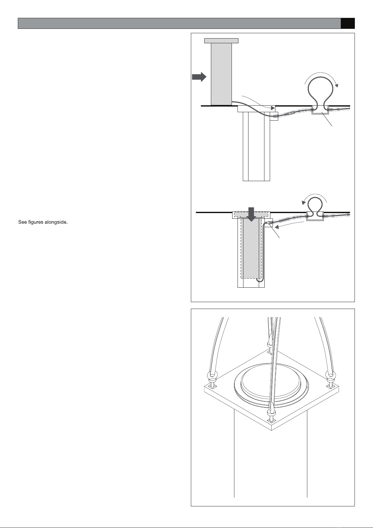
Plan for a junction box in proximity (max 2/3m) of the bollard (Ref. S),
where about 1m of extra cable should be left. While inserting the bollard,
thanks to this junction box it will be possible to recover/release the cable
When installing multiple bollards, plan on a junction box for each bollard.
When laying the conduit, try to keep the path as straight as possible,
avoiding sharp corners.
Before inserting the bollard into its housing, remove the previously placed
closing or cover making sure that the anchorage housing of the bollard,
represented by the grey area, is cleaned carefully.
After positioning the case, make sure that the open recess is covered
for the entire amount of time that the rising bollard is not inserted,
with covering that is suitable to avoid accidents that may involve per-
sons or property. A sheet metal cover is available as an option.
Attention: The bollard is equipped with a short segment of connec-
tion cable equipped with a male IP68 connector.
Different size extension cords are available (5 to 25 m), , equipped
with a female IP68 connector, for connecting to the control unit.
Bring the two parts of the connector together, aligning the arrow with the
IMPORTANT: You must close the connector fully and in the correct
manner to avoid bending the electrical contacts and to ensure a wa-
terproof seal. Check the connector and the illustrations carefully be-
fore proceeding. Do not force the two parts of the connector for any
reason.
The connector, when correctly put together, guarantees IP68 protec-
tion. The manufacturer cannot guarantee against faults and malfunc-
tions in the event of incorrect connection of the connector.
You are advised to check movement of the connector in the sheathing by
-
ucts if necessary.