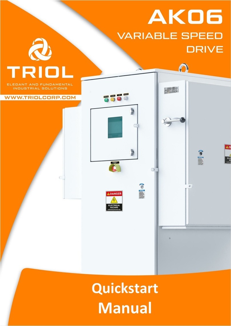
Triol AK06 Programming manual

Troubleshooting
Manual

2AT.654254.050 ver.1.0
Troubleshooting manual

3
AT.654254.050 ver.1.0
Troubleshooting manual
Dear customer
Thank you for purchasing Triol Variable Speed Drive (VSD), the key to your
successful artificial lift strategy.
We are sure that our variable speed drive technologies allow you to improve
operations and maximize your production.
VSD is complete with the following manuals:
•Design Manual;
•Operation Manual;
•Quickstart Manual;
•Programming Manual;
•Troubleshooting Manual;
•Approvals/Standards.
IMPORTANT: The list may be extended with the additional documents (The
Factory Acceptance Testing (FAT) and others) depending on the VSD line.
NOTE: Quickstart manual includes only the necessary basic steps to start VSD with
an induction motor and permanent magnet motor at a well site during pre-
commissioning: set-up VSD to motor and transformer, no-load test and test a VSD
with step-up transformer. During commissioning must be set-up protections,
operation and starting modes in accordance to a field standards or well design.
Explanation of VSD controller settings are given in the Programming manual.
Procedures of starting/stop, recommendations for settings, connection of
external equipment (such as downhole sensors, analog/digital, input/outputs
sensors are given in the Operation manual. In case of any problems or failures
please use Troubleshooting manual. Design manual includes technical
specifications, a set of dimensional drawings and electrical diagrams for Variable
Speed Drives Triol AK06. The list of all kinds of user manuals is discussed at the
placing an order stage. E-documents version for the product is available on the
official Triol Corporation website.
https://triolcorp.us/documents/
Troubleshooting Manual АТ.654254.050 ver. 1.0.
The manual applies to the commercially available Variable Speed Drives Triol
AK06 UD, CP and RD lines with UMKA07 controller for ESP application.

4AT.654254.050 ver.1.0
Troubleshooting manual
Copyright © Triol Trading LLC. 1993-2021 All rights reserved.
No part of this publication may be reproduced or copied without prior written
permission from Triol Trading LLC.
All products and company names mentioned in this manual are trademarks or
registered trademarks of their respective holders.
The information contained herein is subject to change without prior notice for
improvement.

5
AT.654254.050 ver.1.0
Troubleshooting manual
Contents
Safety requirements and personnel qualification ......................................................................7
General description .................................................................................................................9
List and description of alarms and faults ................................................................................10
Replacement of the RMPS + UDP unit..................................................................................... 17
Replacement of the GB unit.................................................................................................... 19
Replacement of the BVN unit. ................................................................................................ 21
Replacement of the 3MDS unit. .............................................................................................. 23
Replacement of the MDN unit................................................................................................. 25
Replacement of the UMKA07 controller. ................................................................................. 27
Replacement of the RisS unit. ................................................................................................ 30
Replacement of the OutM unit. ............................................................................................... 32
Replacement of the extension unit. ........................................................................................ 34
Replacement one extension unit ......................................................................................... 34
Replacement two and more external units ........................................................................... 37
Instruction for updating software UMKA and GB .....................................................................39
Drive static check ..................................................................................................................42
No Load Test......................................................................................................................... 46
Short circuit full load test procedure....................................................................................... 48
Periodic maintenance of VSD Triol ......................................................................................... 51
APPENDIX A ......................................................................................................................... 55
AK06-RD-300…420 with output frequency 200 Hz...................................................................55
AK06-RD-300…420 with output frequency 200 Hz overview ................................................. 56
Electronic compartment ..................................................................................................56
Power input/output compartment ....................................................................................58
External connection section ............................................................................................. 59
AK06-RD-300…420 with output frequency 200 Hz diagnostics flow charts............................ 60
Fans do not work............................................................................................................. 61
VSD indicators are not active ........................................................................................... 62
No input voltage indication (or it does not match) ............................................................. 63
DC bus voltage cannot be measured or measurements are incorrect ................................. 64
Failures of measuring voltage DC in operation, DC overvoltage, DC undervoltage ............... 65
Supply network currents 1 differs from network 2 by more than 20% ................................. 66
No connection with Downhole Measuring System (Sensors)..............................................67

6AT.654254.050 ver.1.0
Troubleshooting manual
No data on ACS (SCADA) ................................................................................................. 68
Digital inputs do not work ................................................................................................ 69
Analog Inputs do not work ............................................................................................... 70
No supply voltage on the surface unit............................................................................... 71
Constant «Emergency stop» is displayed .......................................................................... 72
Constant «Discr T» failure is displayed ............................................................................. 73
Diagnostics of phase failure............................................................................................. 74
Output current are not measured or measurement are incorrect ........................................76
The VSD diagnostics during Power Switch failure (stopped) .............................................. 77
Replacing of an inverter current sensors. ......................................................................... 78
Main fan unit replacing .................................................................................................... 82

7
AT.654254.050 ver.1.0
Troubleshooting manual
Safety requirements and personnel qualification
All the activities on installation, mounting, dismantling, operation and mainte-
nance of a Variable Speed Drive must be carried out in conformity with effective
local and electrical codes and regulations. Improper installation and operation of
the drive may result in personal injury or equipment damage. There is a deadly
level of voltage in drive’s cabinet. When working on installation, maintenance, re-
pair, it is vital to monitor the absence of voltage at the input and output terminals
of VSD.
Before start working with VSD the staff must:
•be specially trained and examined in labor protection issues;
•attend a preliminary medical examination (when hired for work) and peri-
odic health examinations (during the entire labor activity);
•have electrical safety qualification.
At conducting connection to the power supply line there a special attention
must be paid to ensuring of reliable grounding of VSD casing. Grounding re-
sistance must meet the local and national requirements.
At executing any work inside Variable Speed Drive the following safety
measures must be performed:
•circuit breaker ON/OFF must be placed to
«OFF» position;
•leading-in cables must be de-energized;
•warning tags must be put «ON»;
•make sure that leading-in cables are de-ener-
gized and ground them.
* –circuit breaker handle may change place in different
VSD’s types.
ATTENTION! Filter power capacitors conserve the charge hazardous to
life within 5 minutes after de-energization! Prior to execution of work
inside the cabinet make sure that capacitors are de-energized. Filter
power capacitors conserve the charge hazardous to life within 5
minutes after de-energization!
ATTENTION! It is prohibited to disconnect and connect detachable
joints if supply voltage is available. Electronic control units of Variable
Speed Drives contain components made on the basis of metal-oxide-
semiconductor (MOS) technology excluding the action of static
electricity. If you need to touch some MOS component, ground your
body and the tools to be used.

8AT.654254.050 ver.1.0
Troubleshooting manual
Safety Recommendation
The drive must be installed, adjusted and serviced by qualified electrical
maintenance personnel. Improper installation or operation of the drive may cause
injury to personnel or damage to equipment. The drive must be installed and
grounded in accordance with local and national electrical codes. There is a deadly
level of voltage in drive’s cabinet. Extreme care must be taken to ensure all power
sources are disconnected before starting installation, maintenance and repair
jobs. Whenever a drive containing a SCADA or telemetry connection is to be re-
paired or serviced, the service man must disconnect any communication devices
attached to the drive to prevent unexpected start commands from the remote
control system. Service men must be aware that there could be more than one
remote telemetry connection and that all of them must be disabled or discon-
nected for the duration of the repair period. Once repairs are completed, the te-
lemetry connections must be reestablished.
Personal Protective Equipment (PPE)
The basic personal protection equipment (PPE) required for field service in-
cludes, but is not limited to, steel toe shoes, safety glasses and a hard hat. If elec-
trical configuration or maintenance is performed on potentially energized circuits,
personal protective equipment is required to minimize the danger or electrical
shock, arc flash and/or arc blast. The level of PPE required can vary based upon
the available electrical energy available at the installation site. If any doubt exists,
consult and employ the recommendations published in the National Fire Protec-
tion Code, NFPA-70E.
Safety Procedures
Work inside the cabinets must be performed with the power off. Isolate energy
source(s) and use proper Lock Out/Tag Out (LOTO) procedures and Personal Pro-
tective Equipment (PPE) to ensure personnel safety. The drive also contains
stored sources of energy in the form of capacitors. Allow sufficient time after
power is removed for those capacitors to discharge to a safe level below 50 V DC.
The bleed resistors attached to the capacitors reduce the voltage to safe levels
within five minutes of power down. Confirm removal of energy source using a
proven voltage indicator device.

9
AT.654254.050 ver.1.0
Troubleshooting manual
General description
The Troubleshooting manual contents comprehensive step-by-step instruc-
tion with description all possible alarms, faults and actions for their diagnostic
and repair.
Variable Speed Drive cabinet has five separate sections: power section with
control system, section of power winding, input / output cabinet, gauge
connection cabinet, extension units connection cabinet.
Inputs and outputs terminals in VSD, located in same cabinet on the
backside of the cabinet.

10 AT.654254.050 ver.1.0
Troubleshooting manual
List and description of alarms and faults
Troubleshooting of VSD at start motor, fault finding charts are given in Table be-
low:
№
Potential problem/Message
on the controller display
Probable causes
of message displaying
Remedies
1
The screen of the controller
UMKA 07 does not light up and
the control lamps of the VSD
status do not light
Perhaps the mains power is not
supplied to the control system
Supply power to the control sys-
tem
It is possible that power breakers
and auxiliaries are turned off
Turn on auxiliaries located in the
VSD and turn on the main input
circuit breaker.
Malfunction of power unit
Change circuit board
Malfunction of UMKA07 control-
ler
Change the controller UMKA07
2
Alarm «Drive connection fail-
ure» is displayed
There is no connection between
the controller UMKA07 and the
drive
Restore electrical connection be-
tween the UMKA07 controller
and the electronics panel
Insert the connectors according
to the VSD diagram
The software between the
UMKA07 controller and the drive
is not compatible
Update the UMKA07 Controller
software to a version compatible
with the firmware of the drive, if
the necessary firmware is rec-
orded in the drive
Change the software of the drive
to a version compatible with the
firmware of the UMKA07 Con-
troller, if the necessary firmware
is recorded in the UMKA07 Con-
troller
3
Alarm «Incompatibility soft
drive» is displayed
The software between the
UMKA07 controller and the drive
is not compatible
Update the UMKA07 Controller
software to a version compatible
with the firmware of the drive, if
the necessary firmware is rec-
orded in the drive
Change the software of the drive
to a version compatible with the
firmware of the UMKA07 Con-
troller, if the necessary firmware
is recorded in the UMKA07 Con-
troller
4
Alarm «Emergency stop» is dis-
played
The emergency stop signal
comes
Press the emergency stop button
Check the integrity of the circuits
from the emergency stop button
and restore their circuits
Electronics malfunction
Replace the electronics panel
with a working one
5
Alarm «R insulation» is dis-
played
«Low insulation of submersible
equipment” signal comes
Replace equipment that has low
resistance (transformer, long
line, submersible unit of teleme-
try)
Replace a faulty insulation meas-
urement unit (surface telemetry
unit or electronics panel if the
equipment does not have telem-
etry)

11
AT.654254.050 ver.1.0
Troubleshooting manual
№
Potential problem/Message
on the controller display
Probable causes
of message displaying
Remedies
Malfunction of the controller
UMKA07
Replace the controller
6
Alarm «Door» is displayed
«Open door»signal comes
Close all VSD doors with a loose
closure; adjust the locks for a
snug fit of the doors to the VSD
itself
Replace the faulty door open
sensor, restore the door open
control circuit
Malfunction of the UMKA07 con-
troller
Replace the controller with a
working one
7
Alarm «Press gauge» is dis-
played
«contact pressure gauge» signal
comes
Ensure the absence of a signal
from the contact pressure
gauge; check the integrity of the
wires from the sensor to the con-
trol system
Correctly connect the contact
pressure gauge to the control
system; correctly configure the
«Press gauge»
Malfunction of the UMKA07 con-
troller
Replace the controller with a
working one
8
Alarm «U,V,W phase power
switch» is displayed
The inverter module or driver in
this phase is defective in the cor-
responding phase
Diagnosis occurs by alternating
phase loops. If the field of loop
alternations did not pass the er-
ror, then the control system is
faulty, if it does, the problem may
be in the module driver or in the
module. Replace driver and mod-
ule together. If the module fails,
it most likely damaged the driver
Defective Electronics panel
Diagnosis occurs by alternating
phase loops. If, after the loop al-
ternations, the error did not
transfer, then the control system
is faulty. If the switch has
passed, there may be a problem
in the module driver or in the
module. Replace the electronics
panel assembly
Faulty cable connecting the elec-
tronics panel and the driver
Replace with a working cable
9
Alarm «Overcurrent p.U,V,W» is
displayed
Faulty current sensor or MDN or
MDS3
Diagnosis occurs by alternating
phase loops. If, after the loop al-
ternations, the error did not
switch, then the control system
is faulty, if the problem has
passed in the current sensor or
in the MDN or 3MDS blocks, re-
place the current sensor if it is
one, or all of them in this phase.
If the alarm does not go away re-
place the MDN or 3MDS blocks
Defective Electronics panel
Diagnosis occurs by alternating
phase loops. If, after the loop al-
ternations, the error did not
transfer, then the control system
is faulty. If the switch has

12 AT.654254.050 ver.1.0
Troubleshooting manual
№
Potential problem/Message
on the controller display
Probable causes
of message displaying
Remedies
passed, there may be a problem
in the module driver or in the
module. Replace the electronics
panel assembly
The adjusted numbers and rated
current of the VSD are entered in-
correctly
Restore factory default rates and
verify their correspondence to
the set rated power of the VSD
(you may need to contact a Triol
service for assistance)
10
Alarm «T° power switch U,V,W»
is displayed
Defective temperature sensor,
driver board, or electronics panel
Diagnosis occurs by alternating
phase loops. If after loop alterna-
tions error did not pass, then the
control system is faulty, if the
switch has passed, there may be
a problem in the temperature
sensor or in the MDN or 3MDS
units. Replace temperature sen-
sor and MDN or 3MDS units or
electronics panel
Overheating protection activation
setpoint «T ° power switch U, V,
W» set incorrectly
Restore factory default rates and
verify their correspondence to
the set rated power of the VSD
(you may need to contact a Triol
service for assistance)
Cooling fan defective
Check the operation of the fan, if
not working, replace it with a
working one
11
Alarm «T° digital sensor» is dis-
played
Faulty temperature sensor, elec-
tronics panel
Diagnosis of the sensor is car-
ried out using a tester. If, at a ra-
diator temperature below 70 de-
grees Celsius and the sensor is
in the open state, the sensor is
faulty. Replace sensor. If the
sensor is faulty and an alarm is
issued, replace the electronics
panel
The cooling fan is defective or
the radiator is clogged
Check the operation of the fan, re-
place it if faulty.
Clean the VSD radiators from
dust and dirt
12
Alarm «Phase failure 1,2,3,4
grid» is displayed
There is no power on one of the
networks or one of the power
switches is turned off
Supply power to all networks.
Check that all power circuit
breakers are fully turned on and
there is power on all phases
There is no contact in the con-
nectors of the rectifier unit, or on
the electronics panel
Restore the connection of the
connectors according to the
electrical diagram, check their re-
liable fixation
13
Alarm «Time-out charge DC»is
displayed
Defective charge unit or power
unit
When a signal is applied to the
charge of a link, there is no
charge, the voltage across the
capacitors does not increase.
Replace charge circuits consist-
ing of charging resistors and
starter or BVN unit
Defective electronic panel
When charging, the voltage rises
but the controller does not meas-
ure this voltage.

13
AT.654254.050 ver.1.0
Troubleshooting manual
№
Potential problem/Message
on the controller display
Probable causes
of message displaying
Remedies
Replace the electronics panel
with a working one
The adjusted number for the
measured voltage in the link is
entered incorrectly
Restore the correct settings for
measuring voltage in the link
14
Alarm «Fail AutoSet» is dis-
played.
On the controller, it is displayed
only during autotest in vector
mode
When conducting auto determi-
nation of motor parameters, it
was not possible to get the cor-
rect data
Connection of motor to the drive
is incorrect, or there is a trans-
former in the scheme
Incorrectly entered parameters
of the measured equipment
(rated current, voltage, PMM
RPM speed)
15
Alarm «Phasing Iabc» is dis-
played
Incorrectly connected current
sensors behind the sine filter
Restore the connection as indi-
cated in the electrical diagram.
Reconnect the connectors to ver-
ify the reliability of the contacts
One of the transformers/current
sensors behind the sine filter is
defective
Check transformers for servicea-
bility by dialing using a tester
with a connected and discon-
nected load current resistor; if a
malfunction is detected, replace
it with a working one
16
Alarm «Charge DC bus» is dis-
played
Defective charge unit or power
unit
When a signal is applied to the
charge of a link, there is no
charge, the voltage across the
capacitors does not increase.
Replace charge circuits consist-
ing of charging resistors and
starter or BVN unit
Defective electronic panel
When charging, the voltage rises
but the controller does not meas-
ure this voltage.
Replace the electronics panel
with a working one
Incorrectly entered adjusted
number of measured voltage in
the link
Restore the correct settings for
measuring voltage in the link
17
Alarm «Short circuit DC bus»
Faulty power unit
When a signal is applied to the
charge of a link, there is no
charge, the voltage across the
capacitors does not increase.
Replace BVN
Defective electronic panel
When charging, the voltage rises
but the controller does not meas-
ure this voltage.
Replace the electronics panel
with a working one
Incorrectly entered adjusted
number of measured voltage in
the link
Restore the correct settings for
measuring voltage in the link
18
Alarm «DC bus Min» is dis-
played
Low supply voltage
During operation, the supply volt-
age draws down and as a result,
the «DC bus Min» is triggered to
provide a stable voltage source
with the required power

14 AT.654254.050 ver.1.0
Troubleshooting manual
№
Potential problem/Message
on the controller display
Probable causes
of message displaying
Remedies
Defective electronic panel
The readings of the voltage
measurement in Ud do not coin-
cide in a smaller direction with
the actually measured ones.
Replace the electronics panel
with a working one
Incorrectly entered adjusted
number of measured voltage in
the link
Restore the correct settings for
measuring voltage in the link
19
Alarm «DC bus Mах» is dis-
played
High supply voltage
During operation, the supply volt-
age is overvalued, as a result of
which the «DC bus Max» is trig-
gered to ensure a connection
with a stable voltage source
Defective electronic panel
The readings of the voltage
measurement in Ud do not coin-
cide upwards with the actually
measured ones.
Replace the electronics panel
with a working one
Incorrectly entered adjusted
number of measured voltage in
the link
Restore the correct settings for
measuring voltage in the link
20
Alarm «Grid Min» is displayed
Low supply voltage
During operation, the supply volt-
age sags; as a result, the «Grid
Min» network is activated to pro-
vide a connection with a stable
voltage source of the required
power
Defective electronic panel
The readings of the voltage
measurement in Ud do not coin-
cide in a smaller direction with
the actually measured ones.
Replace the electronics panel
with a working one
Incorrectly entered adjusted
number of measured voltage in
the link
Restore the correct settings for
measuring voltage in the link
21
Alarm «Grid Max» is displayed
High supply voltage
During operation, the supply volt-
age is overestimated, as a result
of which the «Grid Max» is acti-
vated to provide a connection
with a stable voltage source
Defective electronic panel
The readings of the voltage
measurement in Ud do not coin-
cide upwards with the actually
measured ones.
Replace the electronics panel
with a working one
Incorrectly entered adjusted
number of measured voltage in
the link
Restore the correct settings for
measuring voltage in the link
22
Alarm «Unbalance U» is dis-
played
The supply voltage has a phase
imbalance
During operation, there is a volt-
age imbalance in different
phases; as a result, «Unbalance
U» is triggered to provide a con-
nection to a stable voltage
source

15
AT.654254.050 ver.1.0
Troubleshooting manual
№
Potential problem/Message
on the controller display
Probable causes
of message displaying
Remedies
Defective electronic panel
The readings of the voltage
measurement in the network do
not coincide with the actually
measured
Replace the electronics panel
with a working one
23
Alarm «Phasing CBA» is dis-
played
The supply voltage has an incor-
rect phase sequence
Change the sequence of incom-
ing supply phases
24
Alarm «Backspin» is displayed
There is a backspin motor rota-
tion
Wait until backspin rotation falls
below the setpoint
A tip on a long line running paral-
lel to other live lines
Run shielded cable, or increase
distance from other live conduc-
tors
25
Alarm «SCADA conn. error» is
displayed
Incorrect exchange protocol,
speed and address for communi-
cation with ACS selected
Set the correct exchange proto-
col, speed and address between
VSD and the upper level control-
ler; check what comes from the
controller
Incorrect connection made
Check the connection and make
the connection according to the
connection diagram.
Defective UMKA07 Controller
Replace the controller with a
working one
26
Alarm «USP conn. error» is dis-
played
Block USP not configured
Set speed and address in USP
settings
Block USP out of order
Replace USP
Defective UMKA07 controller
Replace the controller with a
working one
27
Alarm «A-USP conn. error» is
displayed
Block A-USP not configured
Set speed and address in A-USP
settings
Block A-USP out of order
Replace A-USP
Defective UMKA07 controller
Replace the controller with a
working one
28
Alarm «Din8Dout4 conn. error»
is displayed
Block Din8Dout4 not configured
Set speed and address in
Din8Dout4 settings
Block Din8Dout4 out of order
Replace Din8Dout4.
Defective UMKA07 controller
Replace the controller with a
working one
29
Alarm «STM conn. error» is dis-
played
Defective UMKA07 controller
Replace the controller with a
working one
30
Alarm «T° UMKA» is displayed
Defective UMKA07 controller
Replace the controller with a
working one
Protection enable setting low
Set settings according to factory
values
The ambient temperature of the
place where the controller is in-
stalled is too high
Ensure a decrease of ambient
temperature in the compartment
where the controller or VSD is in-
stalled
31
Alarm «Overtorch» is displayed
The program determined that
during operation in PMM the vec-
tors of speed and moment do
not coincide
Check the correctness of the en-
tered motor parameters and VSD
settings and restart.
If it is not possible to eliminate,
please contact Triol service hav-
ing with you the VSD operation
log
32
Alarm «Overshoot» is displayed
The program determined that in
the process of operation in PMM
Check the correctness of the en-
tered motor parameters and VSD
settings and restart.

16 AT.654254.050 ver.1.0
Troubleshooting manual
№
Potential problem/Message
on the controller display
Probable causes
of message displaying
Remedies
mode, vectors have fluctuations
in loading above the specified
If it is not possible to eliminate,
please contact Triol service hav-
ing with you the VSD operation
log

17
AT.654254.050 ver.1.0
Troubleshooting manual
Replacement of the RMPS + UDP unit.
RMPS + UDP replacement procedure is the same for each VSD.
Preparations:
A VSD must be de-energized and disconnected from a power supply.
Using a multimeter, make sure that there is no dangerous voltage on a
DC-link.
Use the following tools for dismantling the RMPS + UDP unit:
•crosshead screwdriver —1 pc;
In case if it is necessary to dismantle RMPS + UDP unit:
1. Take photo or mark all connectors locations.
2. Unplug signal connectors (yellow) from a terminal blocks which is shown at
figure 1 and disconnect the blade clamps shown in red circles.
Figure 1 –Unplug and unscrew connectors of a RMPS + UDP unit

18 AT.654254.050 ver.1.0
Troubleshooting manual
3. Unscrew the screws which fixing RMPS + UDP units as shown at the figure 2
using crosshead screwdriver.
Figure 2 –RMPS + UDP unit final dismantle step
4. Installation of a new RMPS + UDP unit must be done in reversal sequence.
Connection of the RMPS + UDP unit must be carried out according to the
electric circuit and marks.

19
AT.654254.050 ver.1.0
Troubleshooting manual
Replacement of the GB unit.
GB replacement procedure is the same for each VSD.
Preparations:
A VSD must be de-energized and disconnected from a power supply.
Using a multimeter, make sure that there is no dangerous voltage on a
DC-link.
Use the following tools for dismantling the GB unit:
•crosshead screwdriver —1 pc.
In case if it is necessary to dismantle GB unit:
1. Take photo and mark all connectors locations. Special attention must be paid
to the chains not highlighted in red. After installing a new GB unit you must
strictly follow the sequence of connected loops according to the previously
taken photo and tags.
2. Unplug signal connectors (yellow, red) from a terminal blocks which is shown
at figure 3.
Figure 3 –Unplug connectors of a GB unit

20 AT.654254.050 ver.1.0
Troubleshooting manual
3. Unscrew the screws which fixing GB unit from fastening (yellow) as shown
at figure 4 using crosshead screw driver.
Figure 4 –Unscrew the screws which fixing GB unit
4. Remove the GB units from a VSD.
5. Installation of a new GB unit must be done in reversal sequence. Connection
of the GB unit must be carried out according to the electric circuit and marks.
Table of contents
Other Triol DC Drive manuals
Popular DC Drive manuals by other brands
Cole Parmer
Cole Parmer MasterFlex I/P 7591-07 operating manual
ABB
ABB ACS580-01 drives Quick installation and start-up guide
ForceDoor
ForceDoor BASE70 Instructions and user guide
ABB
ABB ACS380 Series Firmware manual
Enerpac
Enerpac HMT Series Operation and maintenance manual
Pfeiffer Vacuum
Pfeiffer Vacuum TC 1200 E74 operating instructions
