Triple Plus CLM User manual

Installation & Operation Manual
Triple CLMTM
1

Leak management and damage prevention
CLMTM
2

Triple+ CLM™line of products is the most comprehensive leak management
and damage prevention solution in the market. The battery operated system
includeswireless water flood detectors, shutoff units and a HUB. Signal repeaters can
be included if necessary. The HUB is connected to the Triple+ Cloud, which End-Users
and Installers are connected to via user friendly Smartphone Apps.
TheTriple+CLM™servesasaSecureGatewaythatensuresalongrangecommunication
between the connected system components via a secure RF link.
Additionally, the HUB is connected to the internet through a local Router (components
via a secure RF link).
Thank you for choosing the Triple+ CLM™
Cloud-based Leak Management
system designed to detect water leaks and prevent the
subsequent damages. Triple+ CLM™ system will give you
peace of mind while at home and away.
Safe Connected Property
3

The primary advantage of the Triple+ CLM™ lies in the
simplicity and completeness of the solution. Having a
wireless and battery operated system assures that the
installation is handled in minutes without the need to trench
cables or involvement of an electrician.
The Triple+ CLM™ smartphone App offers a true remote
management regardless of being home or away. The Triple+
CLM™ system is fully resilient to any Internet communication
failure and will work in its autonomous offline mode,
providing a complete protection of the premises against
water leak damages.
With the Triple+ CLM™ You have the peace of mind and you
know that your property is safe.
Either in a new or existing property, Triple+ introduces a
new era in the water leak damage prevention. Installations
are guaranteed to be handled in minutes. There is no need
to trench communication or power cables during the
installation of leak management system. The Triple+ CLM™
fully address the most demanding needs and requirements
of the professional installer in the industry and eliminates the
boundaries for future system derivatives.
Triple+ CLM™ smartphone App
Stay in full control of your
property
4

5

General Info
Warnings
This product was designed to prevent water leak damages and as
such should be used for water piping only.
Please read through the instructions carefully and follow the steps
of the system’s installation.
Please maintain this document in a safe place for future reference.
When in any doubt, contact your authorized distributor or installer.
Battery replacement
Installation and/or replacement of unit batteries should be performed
6

System components’ placement limitations
HUB/
Repeater
Flood
Sensor
Integrated
shutoff unit Actuator
Metal cabinet
installation
Indoor use
Outdoor use
CLMTM
System component pairing and positioning
Triple+ CLM™
activated using the mobile installer’s App. Please look for Triple+ CLM™
Installer App in Google Play for Android OS-based smartphones or in
the App Store for iOS devices.
The professional installer will pair the system components, install
them on permanent locations within the premises, verify that they
communicate properly between them and the system is ready to be
monitored and controlled via your End-User smartphone App. It can
function either in a wired LAN (local area) or wireless network.
7

Triple+ CLM™ HUB performs the functions of a system gateway. It is used to
provide access to the Internet or a private computer network. It can function in
a wired LAN (local area network), in a wireless-only LAN (WLAN), or in a mixed
wired/wireless network, depending on the need. Once paired by the professional
installer using the Triple+ CLM™ Installer’s App, the HUB is ready for action.
Triple+ CLMTM HUB
The HUB allows understanding of devices’ state
& Remote control of water shutoff units.
8

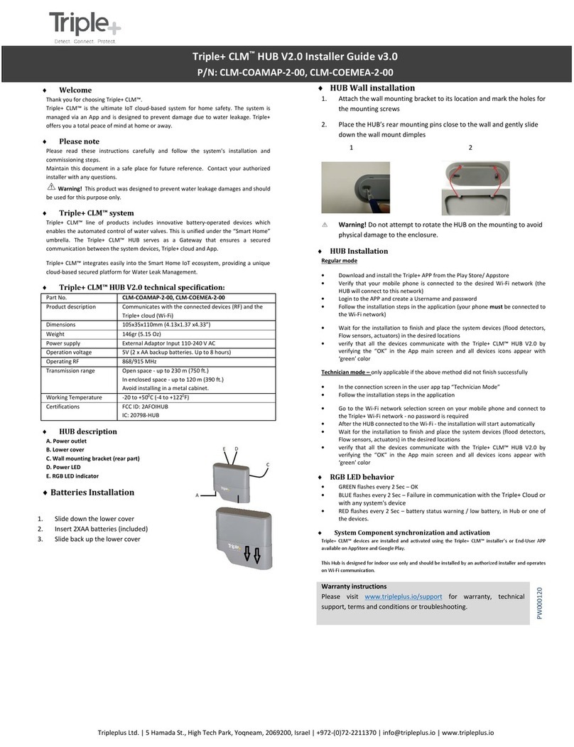
A_Power cable.
B_Table mount bracket.
C_Lower cover.
D_HUB circuit body
E_RGB LED indicator.
F_Wall mounting bracket (on the rear part)
+ HUB description
DE
C
AB
F
9

When interested in HUB wall mounting, please follow the following instructions:
+ HUB installation
1. Detach the HUB from the table stand
as described below.
2. Attach the wall mounting bracket to intended
location and mark the holes for the
mounting screws.
3.
Plug the LAN cable into the LAN inlet, if the
HUB will be permanently operated via the LAN.
4. Position the HUB on its permanent location. For
wall mounting, bring the HUB’s rear mounting
pins close to the wall and gently slide it down the
wall mount’s dimples. Please do not attempt to
rotate the HUB on the mounting in order to avoid
physical damage to the enclosure.
5. For table mounting, connect the table stand
to the HUB and place it on the table.
External
Adaptor
Jack
LAN Inlet
10

+ Expected HUB LED behavior
1. Faultless communication of the HUB with all the components and with the server :
The HUB RGB LED will repeatedly blink in GREEN every 5 seconds.
2. Failure in communication with the server or with any of the system components:
The HUB RGB LED will repeatedly blink in BLUE every 5 seconds.
3. Battery status of at least one the shutoff units is too low and is not allowing to
close it (them) in case of leak event (installation/reset):
The HUB RGB LED will repeatedly blink in RED every 5 seconds.
4. Reset to factory settings:
The HUB RGB LED will be GREEN steady for 10 seconds after the unit reset.
11

The Triple+ CLM™ flood detectors are to be installed in places probe
to water floods or leaks. When a puddle of water is detected, wireless
signal is dispatched to initiate closure of the shutoff unit(s) and push
Flood Detector Setup
Detect the water flood
12

1_Indication LED
2_Water detector
3_Battery housing cover
4_Wall mount bracket
5_Double-sided adhesive tape application locations (rear)
+ Flood Detector description
1
4
3
2
5
13

+ Flood Detector installation
1. Open the battery
housing cover
by pulling it
towards the cable,
while holding the
detector body.
2. Remove
the cover and
expose the
battery housing.
3. Install 2 AAA
batteries in the
battery housing,
please note
the polarity
marking.
4. Close the
battery housing
cover.
5. Apply the attached
double-sided adhesive
tape strips to the battery
housing cover in the
picture.
6. Choose the position and height from the floor level most suitable for
installation, so during flooding detector’s only electrodes would get wet.
Fix both parts of the detector to the wall using the double sided adhesive
that the box will not be exposed to water. The flood detector contains an
electronic circuit and is not within a watertight casing (the two electrodes
are the only part that should come in contact with water).
14

+ Expected Flood Detector LED behavior
+ Flood Detector installation limitations
Places where the detector should not be installed or positioned at:
Within a metal cabinet or anywhere that might influence wireless
communications.
Where the temperature exceeds the range between -20C and +50C degrees
(-4F and 122F).
Where there is an apprehension of being hit or damaged.
In an external place where exposed to rain and direct sunlight and/or
to the elements.
In such a case, the unit should be installed in a water tight plastic casing.
Where there is humidity
1. GREEN blink once in 30 seconds – all is OK
2. RED blink once in 30 seconds – communication problems
3. RED blink once in 10 seconds – ongoing water leak
4. BLUE blink once in 30 seconds –
15

The Integrated ¾”-pipe diameter compatible Shutoff unit is installed on the
main water supply pipe within the premises (or outdoors, in a water tight plastic
casing) and controls the water flow within the pipeline. When needed, using
standard plumbing adapters, the unit can interface various pipe diameters.
Integrated Shutoff Setup
Controls the water flow
1.
sprinkler line.
2. Ensure easy access to the battery housing (opened with a screwdriver)
ensure a minimal access space of 30Cm/1Ft.
3. Ensure easy access to the manual override handle.
16

1_Closing/ opening handle.
2_Close/ open dial.
3_Disconnection unit (valve) body.
4_Battery cover
5_Entry/ exit 3/4” adapter.
6_Base for non-wall mounted valve
7_Base for wall mounted valve.
+ Integrated Shutoff unit description
1
2
3
4
5
7
6
17

1. Installation and/or replacement of a battery should be performed
by authorized personnel.
2.
3. Locate the most suitable place for installation on the water line (as indicated
above.)
4. Shut down the water supply, using the main valve of the building or site.
5. Dismantle the water line connectors in a way that would leave a gap suitable
for installing the 3/4” valve.
6. Install the unit on the water line.
7. Should it be required to have a flexible water pipe for mounting the disconnection
unit on the wall, dismantle the base unit by removing 4 screws to replace it with
the appropriate base unit.
8. Mark the holes’ position on the wall, drill and attach 4 studs and screws.
9. Manual opening and closing of the valve handle should be possible after installation.
10. Enable passage of water in the main line and prevent leaks or drippings.
11. Ensure easy access to the battery housing (opened with a screwdriver) -
ensure a minimal access space of 30cm\1ft.
12. If unit wetting is probable, install an external protective casing.
+ Integrated Shutoff unit installation
18

19

The wireless, battery operated water and gas Shutoff unit is installed on any
manually requested by the user. This actuator is mounted on a ISO5211 flange
using 2 screws, provided with the installation kit. It is IP68-rated, meaning that its
enclosure is both dust and water tight and can also be submerged into water.
Triple+ CLM™ Actuator Shutoff Unit
20
Table of contents
Other Triple Plus Control System manuals

