Trolex TX9042 User manual


TX9042 User Manual
TX9042-UM-EN-02 3
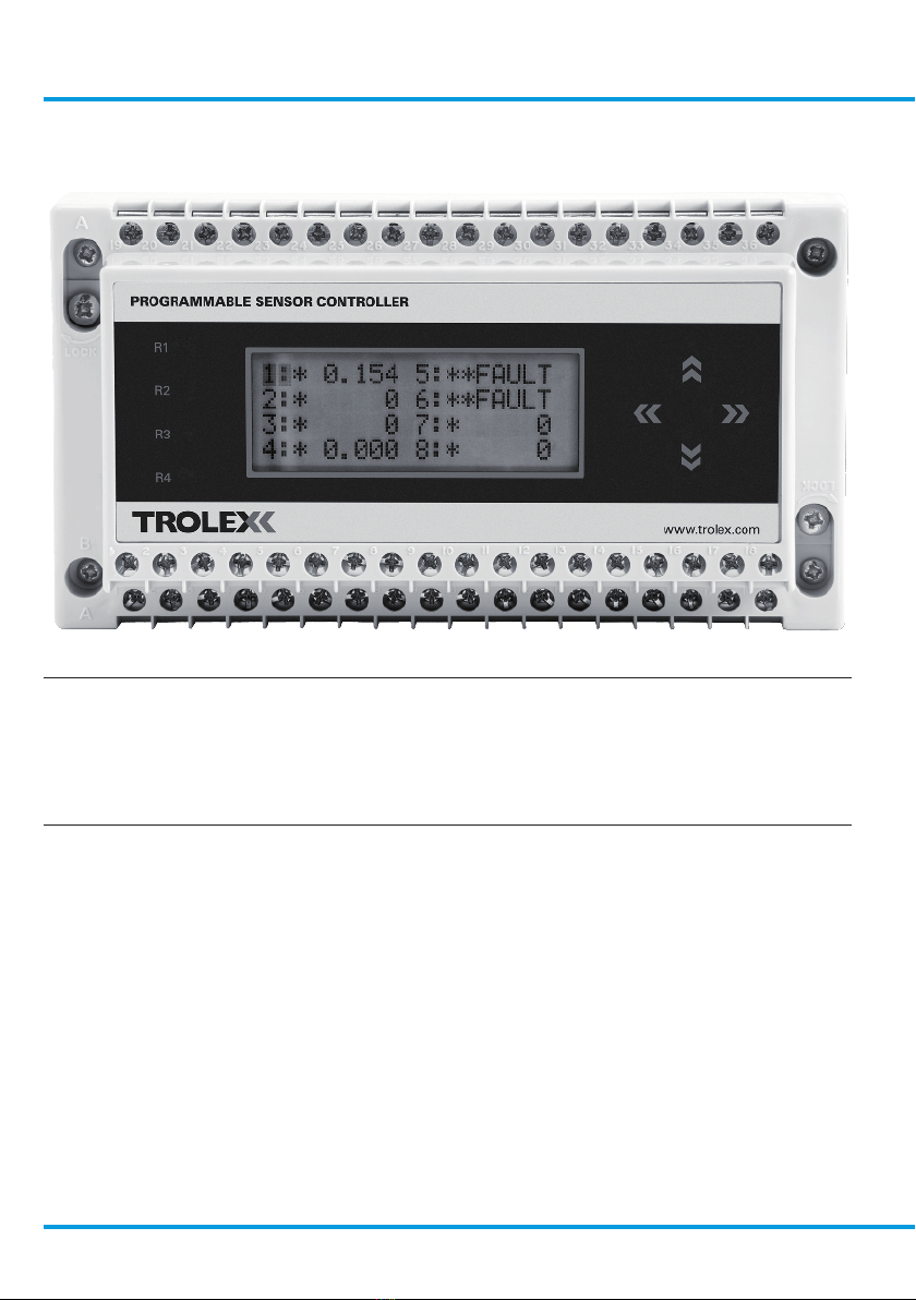
TX9042 Programmable Sensor Controller (PSC)
Contents
1. Product Overview 5
1.1 Operating Features 5
1.2 Application 6
1.3 Product Options 7
1.3.1 TX9042 PSC Input Module
Types 7
1.4 Dimensions 8
1.5 Technical Information 8
1.6 Electrical Details 10
2. Certification 11
2.1 Europe (ATEX) 11
2.1.1 Special Conditions for
Safe Use 11
2.1.2 General Conditions of Use 12
2.2 IECEx Certification 12
2.2.1 Conditions of Certification 12
2.2.2 General Conditions of Use 13
2.3 Russia (Customs Union) 13
2.3.1 General Conditions of Use 13
2.4 South Africa (MASC) 13
2.4.1 Special Conditions for
Safe Use 13
2.4.2 General Conditions of Use 14
2.5 Australia/NZ (ANZEx) 15
2.5.1 Conditions of Safe Use 15
2.6 USA (MSHA) 15
2.6.1 Conditions of Use 15
3. Functional Safety 16
3.1 Overview of Safety Integrity
Level 16
3.2 SIL Suitability 16
3.3 Summary of the Verified
Functional Safety Data 17
3.4 Conditions or Restrictions for
use in SIL Applications 18
3.5 Proof Test 19
3.6 System Configuration
Drawing 20
4. Installation 21
4.1 Precautions 21
4.2 Labelling 21
4.3 Tools and Test
Equipment Required 22
4.4 Mechanical Installation 22
4.5 Connections 23
4.6 Input Channel Configuration 25
4.6.1 Analogue Input Modules 26
4.6.2 Digital Input Modules 31
4.6.3 Display of Connection Details 33
4.6.4 Replacing an Input Module 33
4.6.5 Cable Distance Calculation
for Loop Powered 4 to 20 mA
Sensors 33
4.6.6 Cable Distance for Voltage
Inputs (0.4 to 2 V) 34
4.6.7 Dual Input Signals
(Differential) 34
5. Setup and Calibration 35
5.1 Controls and Indicators 35
5.2 Power-up 37
www.trolex.com

4 TX9042-UM-EN-02
5.3 Signal Display 37
5.4 Reviewing the Input Module
Configuration 38
5.5 Close-up Information Display 38
5.5.1 Close-up 1 Information
Display 39
5.5.2 Close-up 2 Information
Display 42
5.6 Menu of Function 44
5.6.1 Default Values 44
5.6.2 Programming the Operating
Values 44
5.7 Main Menu 45
5.7.1 Entering the Main Menu 45
5.7.2 Escape/Return 46
5.7.3 Communication Setup 47
5.7.4 Clock 49
5.7.5 Keycode Security 49
5.7.6 Interval Period of the Datalog 50
5.7.7 Data Display Review of the
Datalog 50
5.7.8 Clear the Data in the Datalog 51
5.7.9 Relay Reset Mode Options 52
5.7.10 Relay Voting 53
5.7.11 Relay Operation 55
5.7.12 Software Version 55
5.7.13 Self Test 55
5.7.14 Display Cycling 56
5.8 Contrast Control 56
5.9 Channel Function and
Calibration 57
5.9.1 Power On Delay (POD)
Period 58
5.9.2 Scale and Display Settings 60
5.9.3 Setpoint Characteristics 79
5.9.4 Fault Signal Alarm
Assignation 85
5.9.5 Threshold Acceptance Level 86
5.9.6 Keycode Security for Each
Channel - 1 to 8 87
5.9.7 Mode Setting for a Digital
Input Module 88
5.9.8 Setting a Digital Failsafe
Input Module 96
5.9.9 Channel Display Mode 99
5.10 Datacommunications 100
5.10.1 RS485 100
6. Maintenance 102
6.1 TX9042 PSC Planned
Preventative Maintenance 102
6.1.1 Introduction 102
6.1.2 TX9042 PSC - Check 102
6.1.3 TX9042 PSC Battery
- Replace 104
6.1.4 TX9042 PSC - Proof Test 104
6.2 TX9042 PSC - Repair 107
6.3 Maintenance Records 107
6.4 Maintenance Log 108
7. Disposal 109
Disclaimers 110
Trademarks 110
Document History 110
Contact Details 110
www.trolex.com
TX9042 User Manual
TX9042-UM-EN-02 5
1. Product Overview
TX9042.55
Up to 8 analogue or digital inputs.
Up to 16 On/Off inputs
RS485 data communications
Data logging facility for up to 26,000 input readings per
channel
1.1 Operating Features
• Up to eight channels of analogue or digital inputs or sixteen on/off inputs
• Input and output functions are programmed directly using the keypad
• RS485 data protocol for integrating multi-point sensor collecting into mine wide
systems
• Accepts analogue or digital inputs from a variety of source types
• Simple to use, just four keys to programme the TX9042 PSC, no special
software and no software programming skills required
• Full functional compatibility with the entire range of Trolex sensors
• Up to 32 TX9042 PSC can be connected to a single mine wide data system
www.trolex.com

6 TX9042-UM-EN-02
1.2 Application
The TX9042 Programmable Sensor Controller (PSC) is for sensor management and
data communications in arduous industrial environments and hazardous areas. It is
suitable for use in SIL 1 and SIL 2 applications, in accordance with any conditions or
restrictions.
The uses of the TX9042 PSC include:
• Underground machinery protection
• Environmental monitoring using a combination of gas sensors and flow sensors
• Gas detection systems
• Conveyor control
• Pump and compressor monitoring
• Machine condition monitoring
• Fan vibration monitoring
• ITP monitoring
• On-board underground machinery monitoring
• Plant protection
• Data collection from groups of diverse sensors
• Area network sensor collection and monitoring
The data logging facility can be used to record operational trends and to analyse
periods where serious incidents may have occurred. All data acquired can also be
transmitted over a communication link to a remote point. The system can also be
used for collecting sensor information from several distributed monitoring stations
on a mine wide sensor network. Up to 32 sensor collectors can be networked on
a data link and communicated to a central control and monitoring computer via the
data link.
Intrinsically Safe:
TX9042.55
Supply Voltage:
12 V dc from an approved intrinsically
safe power source
www.trolex.com

TX9042 User Manual
TX9042-UM-EN-02 7
1.3 Product Options
TX9042 PSC General Purpose Mining Ex ia
12 V dc - TX9042.55
1.3.1 TX9042 PSC Input Module Types
Input Module Description Mining Ex ia Order Code
Current - 0 to 20 mA P5423.516
Current - 4 to 20 mA P5423.508
Voltage - 0 to 2 V P5423.514
Voltage - 0.4 to 2 V P5423.509
Voltage - 0 to 10 V P5423.515
Flow TX6023 - not lo limited P5423.552
Flow TX6023 - lo limited P5423.553
Flow TX6023 - 4 to 20 mA lo limited P5423.556
Thermocouple - K type P5423.539
Thermocouple - I/R -50 to +400°C P5423.527
PT100 - -50 to +200°C P5423.510
PT100 - -50 to +400°C P5423.513
KTY21 - -50 to +150°C P5423.519
KTY81 - -50 to +150°C P5423.511
KTY84 - 0 to +300°C P5423.512
Flow TX6022 - Flow P5423.528
Flow TX6022 - Pressure P5423.518
ac RMS - 500 Hz to 10 kHz - TX5630 P5423.506.01
ac RMS - 15 to 100 Hz - TX5630 P5423.506.02
www.trolex.com
8 TX9042-UM-EN-02
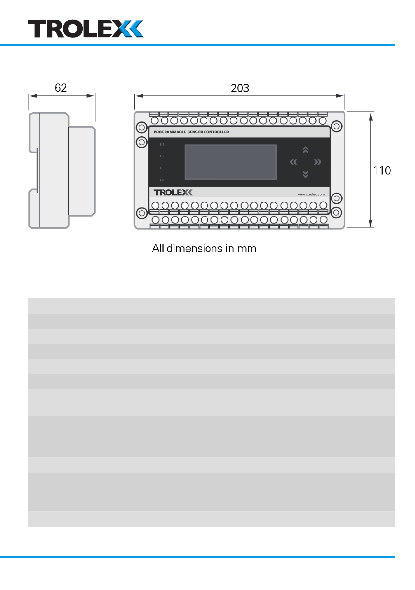
1.4 Dimensions
1.5 Technical Information
Display accuracy +/-0.25% (analogue channels)
Setpoint accuracy +/-0.5%
Ambient temperature limits -10 to +50°C
Electrical connections 4 mm barrier/clamp terminals
Housing material ABS
Nett weight 800 g
Environmental protection Must be housed in a protective metal enclosure
to comply with Intrinsically Safe requirements
Information display LCD screen
20 characters x 4 lines
6 mm high characters
Mounting DIN rail
Microprocessor Microprocessor controlled menu operation, with
non-volatile data retention and 10 bit analogue to
digital conversion (analogue channels)
Setpoints 2 per channel plus Fault signal
www.trolex.com

TX9042 User Manual
TX9042-UM-EN-02 9
Output relays 4 encapsulated reed relays with function
programming
Relay contact rating 200 V
0.25 A
3 W absolute maximum
Checkpoint
Circuits switched by the contacts of the
output relays MUST emanate from a certified
Intrinsically Safe power source and the circuit
parameters must be within Intrinsically Safe
requirements.
Setpoint adjustment 0 to 99% of full scale
Hysteresis adjustment 0 to 99%
Power on delay adjustment 0 to 255 seconds for each channel
Output delay adjustment 0 to 18 hours for each setpoint in one second
steps
Input update period
adjustment
0 to 60 seconds for each channel in 0.05 second
steps
Engineering units menu V, mV, mA, °C, °F, °K, g, kg, mbar, bar, Pa, kPa,
PSI, %, ppm, %RH, mm, m, mm/s, m3/s, rpm,
pps, Hz, kHz, secs, m:s, h:m, m/s, m3/H, m3/m,
A, l/m, g/m, l/s, g/s, l/h and g/h
Fault signal Open or short circuit signal line or sensor fault,
will generate a fault signal, the fault will be
identified and displayed on the LCD screen
Data communications RS485 Modbus
Data logging Up to 26,000 readings with on-demand down
loading
www.trolex.com

10 TX9042-UM-EN-02
1.6 Electrical Details
TX9042.55 - Programmable Sensor Controller (PSC)
Supply voltage: 12 V dc +20%/-2.5% at 125 mA
Output: Modbus protocol
Type of sensor: Flammable
Supply current: 125 mA at 12 V
Relay: 200 V
0.25 A
3 W absolute maximum
Checkpoint
Circuits switched by the contacts of the output relays
MUST emanate from a certified Intrinsically Safe
power source and the circuit parameters must be
within Intrinsically Safe requirements.
www.trolex.com
Other manuals for TX9042
1
Table of contents
Other Trolex Controllers manuals

Popular Controllers manuals by other brands

Digiplex
Digiplex DGP-848 Programming guide

YASKAWA
YASKAWA SGM series user manual

Sinope
Sinope Calypso RM3500ZB installation guide

Isimet
Isimet DLA Series Style 2 Installation, Operations, Start-up and Maintenance Instructions

LSIS
LSIS sv-ip5a user manual

Rockwell Automation
Rockwell Automation 1769-L31 installation instructions


