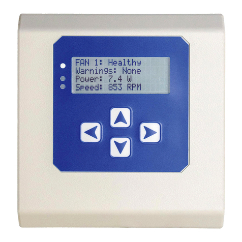
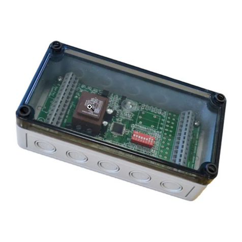
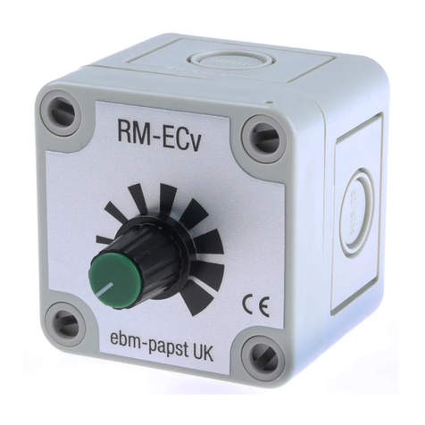
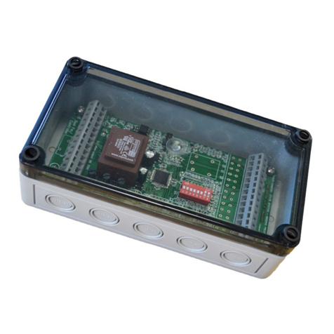
Ebmpapst VTD-60.05-K5C-S Quick guide

the engineer’s choice
Control electronics
VTD-60.XX-K5C-S
Translation of the original operating instructions
(ENU)
VTD-60.13-K5C-S
VTD-60.35-K5C-S
VTD-60.05-K5C-S

2/37 Item no.: HAB 100177146 - 000 · ENU · Change 1.1 · Approved 2023-02-21
Control electronicsControl electronics
VTD-60.XX-K5C-SVTD-60.XX-K5C-S
Contents
1 Introduction ............................................................................................................... 5
1.1 Foreword........................................................................................................................................................5
1.2 Target group ..................................................................................................................................................5
1.3 Written styles in this document ...................................................................................................................5
1.4 Warning notices and notices ........................................................................................................................5
2 Safety information..................................................................................................... 5
2.1 General safety information ...........................................................................................................................6
2.2 Documentation ..............................................................................................................................................6
2.3 Mechanical safety..........................................................................................................................................6
2.4 Standards and directives..............................................................................................................................6
...............................................................................................................................7
2.6 Safety of persons ..........................................................................................................................................7
2.7 Electric/electromagnetic safety....................................................................................................................7
2.8 Intended use ..................................................................................................................................................8
2.9 Improper use..................................................................................................................................................8
...................................................................................................................9
2.11 Transport and storage...................................................................................................................................9
2.12 What to do in the event of malfunctions and irregularities........................................................................9
3 Description ................................................................................................................ 10
3.1 Description of VTD-60.XX-K5C-S..................................................................................................................10
3.2 Nameplate ......................................................................................................................................................10
3.3 Device view ....................................................................................................................................................13
3.4 Status LED .....................................................................................................................................................15
4 Technical data............................................................................................................ 16
4.1 Power .............................................................................................................................................................16
4.2 Motor types ....................................................................................................................................................16
4.3 Mechanical data.............................................................................................................................................16
4.4 Environment ..................................................................................................................................................17
4.5 Controller cycle times ...................................................................................................................................17
4.6 CAN bus .........................................................................................................................................................17
4.7 Encoder supply (rotary encoder/Hall)..........................................................................................................17
4.8 Rotary encoder ..............................................................................................................................................17
4.9 Hall sensors ...................................................................................................................................................18
4.10 Digital inputs..................................................................................................................................................18
4.11 Digital outputs ...............................................................................................................................................18

3/37
Item no.: HAB 100177146 - 000 · ENU · Change 1.1· Approved 2023-02-21
Control electronicsControl electronics
VTD-60.XX-K5C-SVTD-60.XX-K5C-S
4.12 Analog inputs ................................................................................................................................................18
4.13 Dimensional drawings ..................................................................................................................................19
5 Installation ................................................................................................................. 21
5.1 Mounting conditions .....................................................................................................................................22
5.2 Mechanical installation .................................................................................................................................22
5.3 Electrical installation ....................................................................................................................................23
5.4 Connecting control electronics to electricity source .................................................................................26
5.5 Schematic overview .....................................................................................................................................30
5.6 Order of electrical hookup for commissioning ...........................................................................................30
5.7 Wiring examples............................................................................................................................................31
6 Operation ................................................................................................................... 33
6.1 Switching on the control electronics...........................................................................................................33
6.2 Setting operating modes...............................................................................................................................33
6.3 Checking functions .......................................................................................................................................33
...........................................................................................................33
6.5 Parameterization/description of parameters...............................................................................................33
6.6 Setting options using HEX switches (VTD-60.13-K5C-S, VTD-60.35-K5C-S) ............................................33
6.7 Setting options using epTools .....................................................................................................................34
7 Maintenance & error handling .................................................................................. 36
7.1 Cleaning .........................................................................................................................................................36
7.2 Safety checks ................................................................................................................................................36
7.3 Disposal .........................................................................................................................................................36

4/37 Item no.: HAB 100177146 - 000 · ENU · Change 1.1 · Approved 2023-02-21
Control electronicsControl electronics
VTD-60.XX-K5C-SVTD-60.XX-K5C-S
Disclaimer
Contents of operating instructions
These operating instructions have been created with care. However, ebm-papst assumes no liability for the up-to-dateness,
correctness, completeness, or quality of the information provided. Liability claims towards ebm-papst which relate to damage of
a material or non-material nature which was caused by use or non-use of the information presented or by the use of incorrect
and incomplete information are categorically excluded insofar as there is no evidence of deliberate or grossly negligent
culpability on the part of ebm-papst.
Version Date Description of change
1.1 21.02.2023 VTD-60.05-K5C-S control electronics added, designations changed: VTD-60.13-K5SB in VTD-60.13-
K5C-S, VTD-60.35-K5SB in VTD-60.35-K5C-S, general adaptations
Responsibility for documentation
ebm-papst St. Georgen
GmbH & Co. KG
Hermann-Papst-Strasse 1
78112 St. Georgen
Copyright
ebm-papst St. Georgen
GmbH & Co. KG
Hermann-Papst-Strasse 1
78112 St. Georgen
ebm-papst has sole copyright. Duplicating this document or using it without the express consent of the author is prohibited.
Availability of operating instructions
The operating instructions must be available to the user at all times, to ensure the device is used safely. They must be kept at
an easily accessible location at the place of installation, where they can be viewed at all times.
Application
When using the control electronics, it is essential that the safety regulations and the relevant operating instructions in connection
with drives or similar are observed. Read these operating instructions carefully before you start working with the control elec-
tronics. Observe the hazard and warning notices to avoid the risk of injury or malfunctioning.
These operating instructions are to been viewed as part of the control electronics. The control electronics are only to be sold or
passed on together with the operating instructions. Safety regulations and installation instructions may be duplicated and
distributed to inform about potential dangers and their prevention. ebm-papst is always looking to advance and enhance its
products. As a result, products may differ from these operating instructions. The user must check this before use and take into
account any deviations.
Subject to change.
You can find the respective current version of these operating instructions on our homepage: www.ebmpapst.com

5/37
Item no.: HAB 100177146 - 000 · ENU · Change 1.1· Approved 2023-02-21
Control electronicsControl electronics
VTD-60.XX-K5C-SVTD-60.XX-K5C-S Introduction
1 Introduction
1.1 Foreword
These operating instructions outline the application possibilities, installation, operation, and programming of the control electron-
ics specified on the title page.
When installing and operating the control electronics, all of the safety information listed in Chapter 2 must be adhered to.
Abroad, the corresponding laws, guidelines, and regulations of the relevant country also apply.
Read these operating instructions carefully before you start working with the control electronics. Observe the following warning
notices in order to avoid risk of injury or malfunction of the control electronics.
1.2 Target group
These operating instructions are only intended for qualified and trained specialist personnel with knowledge of electronics and
mechanics.
1.3 Written styles in this document
In these operating instructions, the meaning of certain sections is indicated through various means.
Descriptive text is shown without a preceding symbol.
• Text preceded by a dot (•) indicates a list introduced by a heading.
Underlined blue text indicates a hyperlink, which can be clicked on in the PDF document. The relevant website is then called up.
Underlined green text indicates a non-interactive cross reference, which refers to the relevant chapter of the help file in the
"epTools" software.
1.4 Warning notices and notices
Warning notices and notices are always shown before an instruction where carrying out the action could result in a hazard or
material damage.
In this documentation, the following warning notices are used:
DANGER
Hazard
This notice indicates a hazard with a high level of risk that will directly result in death or severe bodily injury if
it is not avoided.
→This arrow highlights a corresponding precautionary measure in order to prevent the hazard.
WARNING
Hazard
This notice indicates a hazard with a moderate level of risk that may possibly result in death or severe bodily
injury if it is not avoided.
→This arrow highlights a corresponding precautionary measure in order to prevent the hazard.
CAUTION
Hazard
This notice indicates a hazard with a low level of risk that may result in light or moderate bodily injury and
material damage if it is not avoided.
→This arrow highlights a corresponding precautionary measure in order to prevent the hazard.
Notices contain information that is particularly important at the relevant point or make the operating steps described easier.
They are emphasized as follows:
NOTE
This notice provides you with recommendations for use and helpful tips.

6/37 Item no.: HAB 100177146 - 000 · ENU · Change 1.1 · Approved 2023-02-21
Control electronicsControl electronics
VTD-60.XX-K5C-SVTD-60.XX-K5C-S
Safety information
2 Safety information
The VTD-60.XX-K5C-S control electronics have been developed based on state-of-the-art electronics and electrical engineer-
ing, as well as recognized guidelines for the safety and protection of users. See also Chapter “2.4 Standards and directives”.
The control electronics may only be operated and serviced by authorized specialist personnel who have fully read and under-
stood these operating instructions. These control electronics must be used with due care and in compliance with the safety infor-
mation outlined in these operating instructions and the country-specific applicable regulations.
2.1 General safety information
Always observe the following safety instructions, regardless of the specific operating conditions:
• Before you start working with the control electronics, switch them off and secure them from switching themselves on again.
• Before opening the control electronics or entering the danger zone, ensure all drives are safely brought to a standstill and are
secured against switching on again.
• Do not modify or convert the control electronics, or fit any attachments to them, without approval from ebm-papst.
• Commissioning may only take place following full verification of compliance with all relevant legal requirements, guidelines
and application-related safety regulations (e.g. accident prevention regulations).
• The safety hazards associated with the control electronics must be reassessed following installation in the end application.
• Keep the workplace clean and tidy. Untidiness in the work area increases the risk of accidents.
2.2 Documentation
When using the control electronics in connection with drives or similar, the relevant operating instructions must also be
observed.
In addition to these operating instructions, "epTools" PC software is required for configuring and parameterizing the control
electronics. Operation is described in the help file in the "epTools" software.
You can find the respective current version of these operating instructions and the "epTools" software on our homepage:
https://www.ebmpapst.com/software.
2.3 Mechanical safety
• Only carry out work when the system/machine is at a standstill.
• Ensure the control electronics have cooled sufficiently.
• Only ever remove the protective devices for repair and assembly work.
2.4 Standards and directives
The control electronics fall under the Machinery Directive, as they concern "partly completed machinery" according to Article 2,
Section g, Machinery Directive 2006/42/EC. Applying a CE marking to the nameplate is prohibited. The declaration of incorpora-
tion according to Annex II, Part 1, Section B, Machinery Directive, 2006/42/EC has been issued.

7/37
Item no.: HAB 100177146 - 000 · ENU · Change 1.1· Approved 2023-02-21
Control electronicsControl electronics
VTD-60.XX-K5C-SVTD-60.XX-K5C-S Safety information
2.5
The following qualification requirements are specified in these operating instructions:
• Qualified electricians: persons who, due to their specialist training and skills, are able to carry out work on electrical
systems and independently identify hazards. A qualified electrician must observe the applicable regulations in their country
for installing electrical equipment (e.g. DGUV (German Social Accident Insurance) in Germany).
• Authorized specialist personnel: persons who have been trained by the operator about the potential hazards when
carrying out their assigned tasks and activities.
Tasks and activities Required skills and knowledge
Installation
• Practical electrical training
• Knowledge of the current electrical safety regulations
• Knowledge of the relevant electrical safety regulations at the workplace
Configuration
• Basic knowledge of the structure and set-up of the described connections and
interfaces
• Basic knowledge of data transfer
Servicing • Practical technical training
• Knowledge of the relevant electrical safety regulations at the workplace
• Only qualified electricians are allowed to install the control electronics, carry out the trial run and perform work on the
electrical system.
• Only authorized specialist personnel are allowed to transport, unpack, operate and service the control electronics.
2.6 Safety of persons
• Provide sufficient protection against accidental contact (e.g. cover electrical contacts).
• Do not wear loose clothing or jewelery.
• Keep hair, clothing, and gloves well away from rotating components.
• Use personal protective equipment (e.g. hearing protection, thermal gloves).
2.7 Electric/electromagnetic safety
DANGER
Electrical charge possible on the control electronics (even when switched off)
Electric shock
→Make sure there is no possibility of contact with the control electronics when installed.
→Before working on control electronics that may be electrically charged, make sure that no charge is
present any more. Use a two-pole voltage tester.
→Wait five minutes after disconnecting the voltage at all poles before opening the control electronics.
• Depending on the environmental conditions, regularly check the control electronics and connected cables for damage.
• Only use cables and plug connections approved by ebm-papst.
• Immediately replace defective cables and loose connections.
• Ensure EMC capability in the end device/installation state, e.g. with shielding.
• Provide suitable measures for avoiding impermissible electromagnetic interference emissions, such as shielding.
• Use open-loop and closed-loop control devices for influencing the electromagnetic radiation.

8/37 Item no.: HAB 100177146 - 000 · ENU · Change 1.1 · Approved 2023-02-21
Control electronicsControl electronics
VTD-60.XX-K5C-SVTD-60.XX-K5C-S
Safety information
2.8 Intended use
These control electronics are an installation product. It is intended solely for industrial use in devices and machines and does
not have any independent function. The control electronics are not intended to be passed on to end customers. The end
manufacturer must ensure all of the motor and electronics combinations are qualified for their intended application and are
validated as having overload and locking protection. The end manufacturer is responsible for the end product and must take
adequate safety measures. Customer equipment must be capable of withstanding the mechanical and thermal stresses that can
arise from these control electronics. This applies for the entire service life of the equipment in which these control electronics are
installed. Any other usage above and beyond this does not conform with the intended purpose and constitutes misuse of the
control electronics.
Compliance with the intended use also demands:
• Observing the operating instructions.
• Using the control electronics according to the permissible ambient temperatures and nominal data (see Chapter “4 Technical
data” on page 16).
• Only using the control electronics in stationary systems.
• Starting up the control electronics only after installation in the customer equipment.
• Operating the control electronics with all protective devices.
• Performing all maintenance work.
2.9 Improper use
In particular, using the control electronics in the following ways is prohibited and could lead be hazardous:
• Operation of the control electronics in technical systems for which there are special requirements with regard to safeguarding
against failure.
• Operation of the control electronics in aircraft or spacecraft.
• Operation of the control electronics in residential environments.
• Operation of the control electronics in railway vehicles, motor vehicles, and ships.
• Operation of the control electronics in potentially explosive atmospheres (explosion protection area).
• Operation in medical equipment with a life-sustaining or life-support function.
• Use as a safety component or to perform safety-related functions.
• Operating the device with protective devices that have been tampered with or completely or partially disassembled.
• Operation with extreme vibrations.
• Painting of the control electronics.
• Unfastening of connections (e.g. screws) during operation.
• All other applications not listed as intended uses.
DANGER
Risk of injury
Potential dangers in the event of non-compliance include personal injury and property damage due to
reduced service life or explosions caused by elevated surface temperature or sparking.

9/37
Item no.: HAB 100177146 - 000 · ENU · Change 1.1· Approved 2023-02-21
Control electronicsControl electronics
VTD-60.XX-K5C-SVTD-60.XX-K5C-S Safety information
2.10
Only operate the control electronics in their original and faultless condition. Retrofitting, modifying, and converting the control
electronics is strictly prohibited. Any modifications you wish to make must always be agreed with ebm-papst first.
ebm-papst is not liable for any conversions and modifications carried out which have not been expressly approved by us. This
also includes any damage resulting from the use of non-original parts or through operating the device outside of the agreed
parameters.
2.11 Transport and storage
• Transport and store the control electronics in their original packaging only.
• Store the control electronics so that they are protected from environmental influences and dirt until final installation.
• We recommend storing the control electronics for no longer than one year in order to guarantee trouble-free operation and
the longest possible service life.
• If the device is stored for an extended period, it must be connected and started at least every two years.
• Comply with the ambient temperatures specified in Chapter “4 Technical data” on page 16.
2.12 What to do in the event of malfunctions and irregularities
The device may only be used in perfect condition. If you notice irregularities, malfunctions, or damage, shut down the device
immediately and inform your manager (if there is one).
The user/owner of the control electronics and associated accessories should address all complaints about the product to one of
ebm-papst's representatives or directly to:
ebm-papst St. Georgen
GmbH & Co. KG
Hermann-Papst-Strasse 1
78112 St. Georgen

10/37 Item no.: HAB 100177146 - 000 · ENU · Change 1.1 · Approved 2023-02-21
Control electronicsControl electronics
VTD-60.XX-K5C-SVTD-60.XX-K5C-S
Description
3 Description
3.1 Description of VTD-60.XX-K5C-S
The VTD-60.XX-K5C-S external control electronics are a compact 4-quadrant controller for operating BLDC motors. The control
electronics are designed for nominal voltages of 24 V DC and 48 V DC, as well as peak currents of up to 50 A/100 A. It offers
speed, torque, and positioning mode and has integrated digital inputs and outputs as well as analog inputs. An integrated MPU
enables the control electronics to be freely programmed, making them ideal for use in intralogistics applications such as
crossbelt sorters, warehouse shuttles, and driverless transport systems, as well as other applications in the field of automation.
Selecting the operating modes and parameterizing the speed, torque, and position is carried out via the parameterization
interface CANopen. The control electronics have integrated overvoltage, undervoltage, and overtemperature monitoring. The
status of the control electronics is indicated by three LEDs.
3.2 Nameplate
The nameplate with the relevant control electronics characteristics is applied to the exterior of the housing.
3.2.1 Nameplate VTD-60.05-K5C-S
②
⑦
⑫
⑤
③ ④
⑥
⑧
⑨
⑪
⑩
①
VTD-60.05-K5C-S nameplate legend
Item Designation Item Designation
①Serial number (on side of housing) ⑦Nominal current
②Control electronics type: VTD = Variotronik ⑧Protection class
③Type description: 60 = 60 V DC (max. permissible power supply)
05 = 5 A (permissible continuous current at 24 V DC) ⑨Country of manufacture
④K5 = position controller with BUS interface
C = CANopen
S = plug connection
⑩Production site
⑤Item number ⑪Country code
⑥Nominal voltage ⑫Company logo

11/37
Item no.: HAB 100177146 - 000 · ENU · Change 1.1· Approved 2023-02-21
Control electronicsControl electronics
VTD-60.XX-K5C-SVTD-60.XX-K5C-S Description
3.2.2 Nameplate VTD-60.13-K5C-S
CAN + I/O
X3
10
9
11
8
7
12
4
3
5
2
1
6
Din1
Din0
Din2
+Ain0
+U e 24V
Din3
Lo
Hi
Dout0
-Ain0
GND
GND
- CAN -
21
11
01
9
8
41
31
5
4
3
2
1
7
6
B
A
3H
2H
1H
U+
V5
xnI
B/
A/
3H/
2H/
1H/
DNG
xnI/
Encoder + Hall
X2
I/O
X4
Motor + Power
X1
6
3
5
2
4
1
DNG
cM
bM
EF
aM
U+
p
Node-ID
Hi
0
1
2
3
4
5
6
7
8
9
A
B
C
D
E
F
Lo
0
1
2
3
4
5
6
7
8
9
A
B
C
D
E
F
6niD
1tuoD
1
2
3
4
5
6
5niD
4niD
1niA
7niD
VTD-60.13-K5C-S
994 6013 000
9-60 V 12 A
IP 20
Made in Germany
ebm-papst St. Georgen GmbH & Co.KG
Germany (S)
@ 24 V
①
②
⑩
③ ④
⑤
⑥
⑦
⑨
⑧
⑪⑫
VTD-60.13-K5C-S nameplate legend
Item Designation Item Designation
①Company logo ⑦Nominal current
②Control electronics type: VTD = Variotronik ⑧Protection class
③Type description: 60 = 60 V DC (max. permissible power supply)
13 = 13 A (12.5 A rounded, permissible continuous current at 24 V DC) ⑨Country of manufacture
④K5 = position controller with BUS interface
C = CANopen
S = plug connection
⑩Serial number
⑤Item number ⑪Production site
⑥Nominal voltage ⑫Country code

12/37 Item no.: HAB 100177146 - 000 · ENU · Change 1.1 · Approved 2023-02-21
Control electronicsControl electronics
VTD-60.XX-K5C-SVTD-60.XX-K5C-S
Description
3.2.3 Nameplate VTD-60.35-K5C-S
CAN + I/O
X3
10
9
11
8
7
12
4
3
5
2
1
6
Din1
Din0
Din2
+Ain0
+U
e 24V
Din3
Lo
Hi
Dout0
-Ain0
GND
GND
- CAN -
Encoder + Hall
21
11
01
9
8
41
31
5
4
3
2
1
7
6
B
A
3H
2H
1H
U+
V5
xnI
B/
A/
3H/
2H/
1H/
DNG
xnI/
X2
Node-ID
Hi
0
1
2
3
4
5
6
7
8
9
A
B
C
D
E
F
Lo
0
1
2
3
4
5
6
7
8
9
A
B
C
D
E
F
I/O
X4
7niD
1tuoD
6niD
1
2
3
4
5
6
5niD
4niD
1niA
Motor + Power
X1
6
3
5
2
4
1
DNG
cM
bM
EF
aM
U+
p
VTD-60.35-K5C-S
994 6035 000
9-60 V 35 A
IP 20
Made in Germany
ebm-papst St. Georgen GmbH & Co.KG
Germany (S)
@ 24 V
① ② ③ ④
⑤
⑥
⑨
⑧
⑩
⑪⑫
⑦
VTD-60.35-K5C-S nameplate legend
Item Designation Item Designation
①Company logo ⑦Nominal current
②Control electronics type: VTD = Variotronik ⑧Protection class
③Type description: 60 = 60 V DC (max. permissible power supply)
30 = 30 A (permissible continuous current at 24 V DC) ⑨Country of manufacture
④K5 = position controller with BUS interface
C = CANopen
S = plug connection
⑩Serial number
⑤Item number ⑪Production site
⑥Nominal voltage ⑫Country code

13/37
Item no.: HAB 100177146 - 000 · ENU · Change 1.1· Approved 2023-02-21
Control electronicsControl electronics
VTD-60.XX-K5C-SVTD-60.XX-K5C-S Description
3.3 Device view
3.3.1 VTD-60.05-K5C-S
VTD-60.13-K5C-S device view legend
Item Designation Item Designation
①Interface X1 ③Status LED
②Interface X2
3.3.2 VTD-60.13-K5C-S
VTD-60.13-K5C-S device view legend
Item Designation Item Designation
①Interface X1 ④Interface X4
②Interface X2 ⑤Status LED
③Interface X3 ⑥HEX switch
①
②
③
④
⑤
⑥
①
③
②

14/37 Item no.: HAB 100177146 - 000 · ENU · Change 1.1 · Approved 2023-02-21
Control electronicsControl electronics
VTD-60.XX-K5C-SVTD-60.XX-K5C-S
Description
①
④
⑤
⑥
②
③
3.3.3 VTD-60.35-K5C-S
VTD-60.35-K5C-S device view legend
Item Designation Item Designation
①Interface X3 ④Interface X2
②Status LED ⑤Interface X4
③HEX switch ⑥Interface X1

15/37
Item no.: HAB 100177146 - 000 · ENU · Change 1.1· Approved 2023-02-21
Control electronicsControl electronics
VTD-60.XX-K5C-SVTD-60.XX-K5C-S Description
3.4 Status LED
The control electronics have three LEDs displaying the device status.
VTD-60.05-K5C-S VTD-60.13-K5C-S VTD-60.35-K5C-S
Status LED legend
LED Color State Description
LED0 "Power" Green
Lit up Normal operation
Not lit up No power supply
Flashing Bootloader mode (no firmware)
LED1 "State" Yellow
Lit up CANopen Pre-Operational state (PDOs not active)
Not lit up CANopen Operational state (PDOs active)
Flashing Bootloader mode (flashes in the event of incoming message)
LED2 "Error" Red
Lit up General error
Not lit up No error (normal operation)
Flashing
Number of pulses 1: Short circuit
Number of pulses 2: No supply voltage
Number of pulses 3: Overtemperature
Number of pulses 4: Communication error

16/37 Item no.: HAB 100177146 - 000 · ENU · Change 1.1 · Approved 2023-02-21
Control electronicsControl electronics
VTD-60.XX-K5C-SVTD-60.XX-K5C-S
Technical data
4 Technical data
4.1 Power
Characteristic Unit
Nominal voltage (logic supply UL) V DC 9 to 30 9 to 30 9 to 30
Perm. supply voltage range (U) V DC 9 to 60 9 to 60 9 to 60
Maximum output current A 15 50 100
Permissible continuous output current 1) A
5 (at 24 V)
12.5 (at 24 V)
35 (at 24 V)
4.3 (at 60 V) 26 (at 48 V)
Switching frequency 3) kHz 32 32 32
Nominal voltage (power supply UN) V DC 24 60 24 48 24 48
Logic current draw (at 24 V DC) 2) mA 40 60 70
Maximum commutation frequency (per track) kHz 10 10 10
Minimum terminal inductance mH 0.2 0.2 0.2
Parametrization interface - CANopen CANopen CANopen
Efficiency (in the optimum operating range) % 95 95 95
Approval - UL (certificate avail-
able on request) - -
Material no. - 8315 121 028 994 6013 000 994 6035 000
Commutation: block-shaped commutation (using 3 digital Hall sensors)
1) connecting cable with maximum possible cable cross-section, PWM frequency 32 kHz (asymmetric), ambient temperature 40°C, I/Os and 5 V output, effective current: 5 A
--> 4.1 Aeff, 4.3 A --> 3.5 Aeff
2) output stage off, 5 V output (encoder supply) is unloaded
3) Standard value, other values can be set
4.2 Motor types
Characteristic
Brushed motors ● ● ●
Brushless motors ● ● ●
Linear motors ● ● ●
Stepper motors - - -
4.3 Mechanical data
Characteristic Unit
Dimensions LxWxH mm 74 x 45.5 x 14 110 x 40 x 77 111 x 100 x 30
Weight g 30 310 380
Assembly - Wall DIN rail/wall Wall
Connector - Crimping technology Spring/screw terminals

17/37
Item no.: HAB 100177146 - 000 · ENU · Change 1.1· Approved 2023-02-21
Control electronicsControl electronics
VTD-60.XX-K5C-SVTD-60.XX-K5C-S Technical data
4.4 Environment
Characteristic Unit
Permissible ambient temperature range (TU) °C -25 to +70 -40 to +70 2) -40 to +70 2)
Permissible ambient temperature range
(storage) °C -25 to +85 -40 to +85 -40 to +85
Permissible ambient humidity 1) % 5 to 90 5 to 90 5 to 90
Degree of protection - IP20 IP20 IP20
1) Condensation not permissible
2) Hex switches should not be used for T < -25°C (Node ID can be set using firmware parameters)
4.5 Controller cycle times
Characteristic Unit
Current regulator (CURR) µs 125 125 125
Speed controller (SVEL) µs 250 250 250
Speed controller (VEL) µs 2000 1) 2000 1) 2000 1)
Position controller (POS) µs 2000 1) 2000 1) 2000 1)
3) Standard value, other values can be set
4.6 CAN bus
Characteristic Unit
Protocol - DS301 DS301 DS301
Device profile - DS402 DS402 DS402
Max. baud rate Mbit/s 1 1 1
CAN specification - 2.0B 2.0B 2.0B
Electrically isolated - No No Yes
4.7 Encoder supply (rotary encoder/Hall)
Characteristic Unit
Output voltage V 5 5 5
Maximum output current A 0.2 0.2 0.2
4.8 Rotary encoder
Characteristic Unit
Type - Incremental Incremental Incremental
Signals - A, B, Inx A, /A, B, /B, Inx, /Inx
Max. frequency per track kHz 100 500 500
Input signal (24 V tolerant) V 0 to 5 0 to 5 0 to 5
Signal type - open collector,
single ended Differential, open collector, single ended

18/37 Item no.: HAB 100177146 - 000 · ENU · Change 1.1 · Approved 2023-02-21
Control electronicsControl electronics
VTD-60.XX-K5C-SVTD-60.XX-K5C-S
Technical data
4.9 Hall sensors
Characteristic Unit
Signals - H1, H2, H3 H1, /H1, H2, /H2, H3, /H3
Max. frequency per track kHz 10 10 10
Input signal (24 V tolerant) V 0 to 5 0 to 5 0 to 5
Signal type -open collector,
single ended Differential, open collector, single ended
4.10 Digital inputs
Characteristic Unit
Number -
+/-30V tolerant:
2 (Din0..1)
0-30V tolerant:
1 (Din2)
8 (Din 0 to 7) 8 (Din 0 to 7)
Low level V 0 to 5 0 to 5 0 to 5
High level V 8 to 30 8 to 30 8 to 30
Note - Din2 parallel to
Dout0 1)- -
1) Input voltage must not exceed the supply voltage of the electronics (Ue)
4.11 Digital outputs
Characteristic Unit
Number - 1 (Dout0) 2 (Dout 0 to 1)
Continuous output current A - 1.5 1.5
Loads - Resistive, inductive Resistive, inductive Resistive, inductive
Input signal (24 V tolerant) V Nominal voltage (logic supply UL)
Signal type - Pulse-switching Pulse-switching Pulse-switching
Note - Dout0 parallel to Din2 - -
4.12 Analog inputs
Characteristic
Number 1 (Ain0) 2 (Ain 0 to 1) 2 (Ain 0 to 1)
Signal type – Ain0 +/- 10 V, 12 bit,
single ended
± 10 V, 12 bit,
differential
± 10 V, 12 bit,
differential
Signal type – Ain1 -± 10 V, 12 bit,
single ended
± 10 V, 12 bit,
single ended

19/37
Item no.: HAB 100177146 - 000 · ENU · Change 1.1· Approved 2023-02-21
Control electronicsControl electronics
VTD-60.XX-K5C-SVTD-60.XX-K5C-S Technical data
4.13 Dimensional drawings
VTD-60.05-K5C-S
74.4
45.4
13
16
64.4
30
67
3,5
R2
R2
All dimensions in mm.
VTD-60.13-K5C-S 60
Ø4.2
88.9
77
89
33.7 22.5
39
109.5
All dimensions in mm.

20/37 Item no.: HAB 100177146 - 000 · ENU · Change 1.1 · Approved 2023-02-21
Control electronicsControl electronics
VTD-60.XX-K5C-SVTD-60.XX-K5C-S
Technical data
VTD-60.35-K5C-S
111.1
132.3
26 100 30.8
92.3
3.9
2038
Ø4.3
24.5
10.5
Ø4.3
92.3
3.9
All dimensions in mm.
This manual suits for next models
2
Table of contents
Other Ebmpapst Controllers manuals
Popular Controllers manuals by other brands

Brodersen
Brodersen RTU32S Series Installation and wiring guide

Mitsubishi Electric
Mitsubishi Electric PZ-61DR-E Simple operation manual

Emerson
Emerson Vilter Vission 20/20 Operation and service manual

Rotem
Rotem Platinum Pro installation manual

Resource Data Management
Resource Data Management PR0750-MOB Installation & user guide

Gledopto
Gledopto GL-C-009P User instructions