Trox Technik EK-JZ-FF User manual
Connecting Frame
EK-JZ – FF
Installation manual
Read the instructions prior to performing any task!
for smoke control damper EK-JZ
Promaseal-LW gasket (by others)
to the face of the connecting frame
GB/en

A00000085701, 1, GB/en
Original document
Valid from 12/2022
TROX GmbH
Heinrich-Trox-Platz
47504 Neukirchen-Vluyn, Germany
Germany
Phone: +49 (0) 2845 2020
Telefax: +49(0)2845 202 265
E-mail: [email protected]
Internet: http://www.troxtechnik.com
12/2022
Connecting Frame EK-JZ – FF2

General information
About this manual
This operating and installation manual enables oper-
ating or service personnel to correctly install the TROX
product described below and to use it safely and effi-
ciently.
This operating and installation manual is intended for
use by fitting and installation companies, in-house tech-
nicians, technical staff, instructed persons, and qualified
electricians or air conditioning technicians.
It is essential that these individuals read and fully under-
stand this manual before starting any work. The basic
prerequisite for safe working is to comply with the safety
notes and all instructions in this manual.
The local regulations for health and safety at work and
general safety regulations also apply.
This manual must be given to the system owner when
handing over the system. The system owner must
include the manual with the system documentation. The
manual must be kept in a place that is accessible at all
times.
Illustrations in this manual are mainly for information
and may differ from the actual design.
Copyright
This document, including all illustrations, is protected
by copyright and pertains only to the corresponding
product.
Any use without our consent may be an infringement
of copyright, and the violator will be held liable for any
damage.
This applies in particular to:
Publishing content
Copying content
Translating content
Microcopying content
Saving content to electronic systems and editing it
TROX Technical Service
To ensure that your request is processed as quickly as
possible, please keep the following information ready:
Product name
TROX order number
Delivery date
Brief description of the fault
Online www.troxtechnik.com
Phone +49 2845 202-400
Limitation of liability
The information in this manual has been compiled with
reference to the applicable standards and guidelines,
the state of the art, and our expertise and experience of
many years.
The manufacturer does not accept any liability for dam-
ages resulting from:
Non-compliance with this manual
Incorrect use
Operation or handling by untrained individuals
Unauthorised modifications
Technical changes
Use of non-approved replacement parts
The actual scope of delivery may differ from the infor-
mation in this manual for bespoke constructions, addi-
tional order options or as a result of recent technical
changes.
The obligations agreed in the order, the general terms
and conditions, the manufacturer's terms of delivery,
and the legal regulations in effect at the time the con-
tract is signed shall apply.
We reserve the right to make technical changes.
Warranty claims
The provisions of the respective delivery terms apply
to warranty claims. For purchase orders placed with
TROX GmbH, these are the regulations in section "Vl.
Warranty claims" of the Delivery and Payment Terms of
TROX GmbH, see www.trox.de/en/ .
General information
Connecting Frame EK-JZ – FF 3

Safety notes
Symbols are used in this manual to alert readers to
areas of potential hazard. Signal words express the
degree of the hazard.
Comply with all safety instructions and proceed carefully
to avoid accidents, injuries and damage to property.
DANGER!
Imminently hazardous situation which, if not avoided,
will result in death or serious injury.
WARNING!
Potentially hazardous situation which, if not avoided,
may result in death or serious injury.
CAUTION!
Potentially hazardous situation which, if not avoided,
may result in minor or moderate injury.
NOTICE!
Potentially hazardous situation which, if not avoided,
may result in property damage.
ENVIRONMENT!
Environmental pollution hazard.
Tips and recommendations
Useful tips and recommendations as well as informa-
tion for efficient and fault-free operation.
Safety notes as part of instructions
Safety notes may refer to individual instructions. In
this case, safety notes will be included in the instruc-
tions and hence facilitate following the instructions. The
above listed signal words will be used.
Example:
1. Loosen the screw.
2.
CAUTION!
Danger of finger entrapment when closing
the lid.
Be careful when closing the lid.
3. Tighten the screw.
Specific safety notes
The following symbols are used in safety notes to alert
you to specific hazards:
Warning signs Type of danger
Warning – danger zone.
General information
Connecting Frame EK-JZ – FF4

1 Safety ................................................................ 6
1.1 General safety notes ................................. 6
1.2 Qualified staff ............................................. 6
2 Classification ................................................... 7
3 Installation ...................................................... 10
3.1 Installation side ........................................ 11
3.2 Operating side ......................................... 18
Table of contents
Connecting Frame EK-JZ – FF 5

1 Safety
1.1 General safety notes
Sharp edges, sharp corners and thin sheet metal
parts
CAUTION!
Danger of injury from sharp edges, sharp cor-
ners and thin sheet metal parts!
Sharp edges, sharp corners and thin sheet metal
parts may cause cuts or grazes.
– Be careful when carrying out any work.
– Wear protective gloves, safety shoes and a hard
hat.
1.2 Qualified staff
WARNING!
Danger of injury due to insufficiently qualified
individuals!
Incorrect use may cause considerable injury or
damage to property.
– Only specialist personnel must carry out work.
Specialist personnel
Specialist personnel are individuals who have sufficient
professional or technical training, knowledge and actual
experience to enable them to carry out their assigned
duties, understand any potential hazards related to the
work under consideration, and recognise and avoid any
risks involved.
Safety
Qualified staff
Connecting Frame EK-JZ – FF6
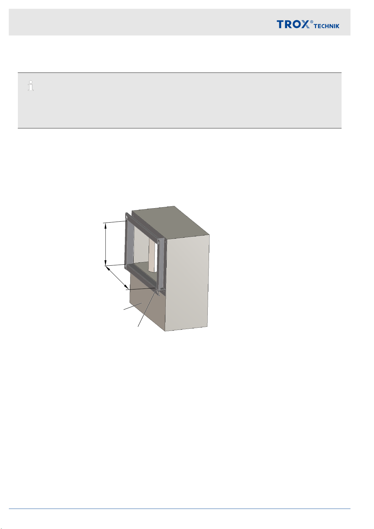
2 Classification
This guide covers the tested solution for TROX type EK-JZ dampers, installed in combination with FF connecting
frames and metal, multi-compartment smoke control ducts insulated with Rockwool FirePro® DuctRock® Slab.
Fig. 1: EK-JZ-FF Test setup
When insulated in accordance with this guide, the classification of TROX type EK-JZ can be assured against the
Declaration of Performance (DoP) and is supported by independent testing by our Notified Body.
The following guide supports classifications upto EI 120 (ved, i↔o) S 1000 Cmod HOT400/30 MA multi
Please Note
The images contained within this guide are rotated for ease of instruction. Application in duct is only certified for
horizontal blade.
INSTALLATION DETAILS ARE SUBJECT TO CHANGE Before commencing any works, check with TROX that
you have the latest version of this guide.
Classification
Connecting Frame EK-JZ – FF 7
Ventilation & smoke extract fire duct system
DUCTROCKâ SLAB
Classification
Connecting Frame EK-JZ – FF8
Connecting frame
Classification
Connecting Frame EK-JZ – FF 9
3 Installation
Please Note
The images contained within this guide are rotated for ease of instruction. Application in duct is only certified for
horizontal blade.
INSTALLATION DETAILS ARE SUBJECT TO CHANGE Before commencing any works, check with TROX that
you have the latest version of this guide.
Note during installation
If EK-JZ is installed with multi-compartment ductwork connected to both sides, this insulation detail
must be applied to both sides of the damper.
The “installation side” is the side of the EK-JZ damper without access to the controls enclosure.
The damper may be installed as shown (controls enclosure at the bottom or top: EK-JZ-*-V with vertical blades
within walls only) or with the controls enclosure on the side (with horizontal blades within walls and ducts).
For clarity on the following instructions, the breadth (width) ‘B’ is the nominal damper size parallel to the blade and
the height ‘H’ is the nominal damper size perpendicular to the blades.
B
H
③
①
Fig. 2: EK-JZ with conneting frame
Personnel:
Specialist personnel
Installation
Connecting Frame EK-JZ – FF10

3.1 Installation side
Preparing the damper connecting frame
handle
②
①
③
②
③
installation side operating side
Fig. 3: EK-JZ frame mount
1. If EK-JZ damper ( Fig. 3 /1) is delivered with loose connecting frame ( Fig. 3 /3), this should be installed to
the damper using the screws provided according to TROX IOM. If the gasket ( Fig. 3 /2) is supplied loose, this
must be applied to the face of the connecting frame before installation to the damper.
Installation on Operating side see
Ä
Chapter 3.2 ‘Operating side’ on page 18
③
①
④
④
Fig. 4: EK-JZ Attach gasket
2. Attach 15 mm x 1,8 mm Promaseal-LW gasket ( Fig. 4 /4, by others) to the face of the connecting frame
( Fig. 4 /3).
Installation
Installation side
Connecting Frame EK-JZ – FF 11

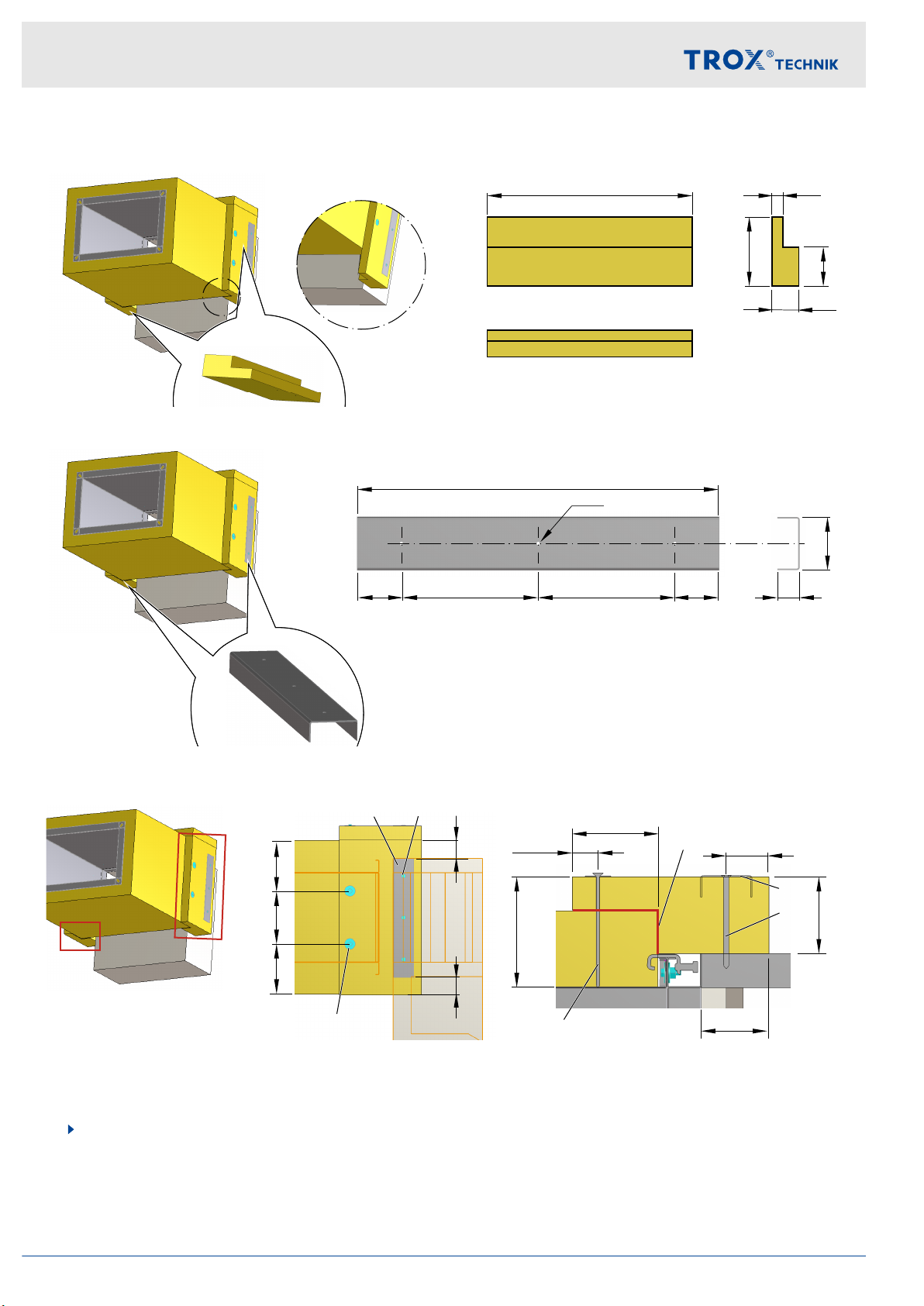
Connect the ductwork to the TROX FF connecting frame
⑥
⑤
③
⑦
Fig. 5: Connect the duct
3. Corners: Attach the duct ( Fig. 5 /5) to the connecting frame ( Fig. 5 /3) with the use of M8 screws ( Fig. 5 /6),
washers and nuts.
Sides: Attach the duct to the subframe with the use of duct clamps ( Fig. 5 /7) or alternatively drill and bolt
together (≤150 mm spacing)
Insulate the ductwork
⑧
t = 90 mm
Fig. 6: Insulate the ductwork
4. Insulate the ductwork according with DUCTROCKâ SLAB ( Fig. 6 /8) to the manufacturers detail. Insulation
should finish at the end of the ductwork (Arrow).
Installation
Installation side
Connecting Frame EK-JZ – FF12

Insulating the FF connecting frame
H + 260
EK-JZ
H + 80
EK-JZ
40
90
130
230
Fig. 7: Insulation block
HEK-JZ
50 50
60
25
≤200 ≤200
-20
∅6
t=1.5
Fig. 8: U-Profile
180
180
140
≤200≤200
140
130
100
30...65 50
80
90
⑪
⑨
⑩
⑨⑩
⑪
⑫
Fig. 9: Install insulation
9 U-Profil
10 5x120 chipboard screw
11 Welding pins
12 Rockwool FIREPRO® Glue
5. Prepare 1x profiled insulation block using Rockwool FirePro® DuctRock® Slab, Fig. 7
Prepare 1x U-Profile (60 mm x 25 mm x 1.5 mm), Fig. 8
Note: Alternative option to use plate washers (≥ 25 mm dia.) in lieu of U-profile.
Install insulation to the damper, Fig. 9
Installation
Installation side
Connecting Frame EK-JZ – FF 13
L₂: B+ 180 + 120
EK-JZ
L₁: B+ 180
EK-JZ 40
90
130
230
L₁L₂
Fig. 10: Insulation block, Note: for Operating side only L2 !
B +80
EK-JZ
50 50
60
25
≤200 ≤200
∅6
t=1.5
Fig. 11: U-Profile
140
140
50
≤200
50
130
100
30...65 50
80
90
⑪
⑨
⑩
⑨
⑩
⑪
⑫
Fig. 12: Install insulation
9 U-Profil
10 5x120 chipboard screw
11 Welding pins
12 Rockwool FIREPRO® Glue
6. Prepare 2x profiled insulation blocks using Rockwool FirePro® DuctRock® Slab, Fig. 10
Prepare 2x U-Profile (60 mm x 25 mm x 1.5 mm), Fig. 11
Note: Alternative option to use plate washers (≥ 25 mm dia.) in lieu of U-profile
Install insulation on the top an bottom of the damper, Fig. 12
Installation
Installation side
Connecting Frame EK-JZ – FF14
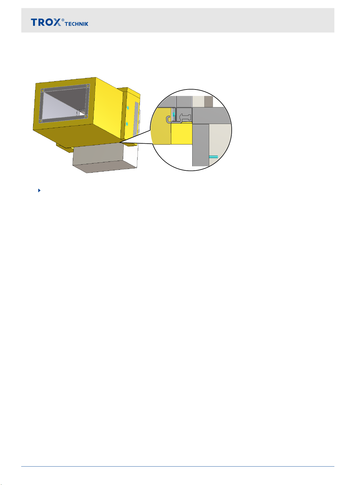
Fig. 13: Infilling the Gaps
7. Infill all gaps between the duct insulation and the damper body with rockwool ensuring no gaps
Installation
Installation side
Connecting Frame EK-JZ – FF 15

H + 260
EK-JZ
90
150
Fig. 14: Insulation block
180180 ≤200≤200
~10
⑪
⑪
⑫
⑩
⑩
Fig. 15: Fixing the Insulation
10 6x180 chipboard screw + washer
11 Welding pins
12 Rockwool FIREPRO® Glue
8. Prepare 1x profiled insulation block using Rockwool FirePro® DuctRock® Slab, Fig. 14
Fixing the Insulation to the damper side, Fig. 15
IMPORTANT: Ensure all rockwool parts are glued together
Installation
Installation side
Connecting Frame EK-JZ – FF16

Fig. 16: Installation side Job completed
9. Insulation process for Installation side completed
Note: Orientation of butt joint between additional insulation layers can be switched to allow sides to cover top /
bottom panels.
Installation
Installation side
Connecting Frame EK-JZ – FF 17

3.2 Operating side
1. For the insulation on the Operating side, perform steps 1-6 according to installation side
Ä
Chapter
3.1 ‘Installation side’ on page 11 .
Prepare the control panel lid
Fig. 17: Control panel lid
2. Remove the handle and the type label
Note: For ease of the following steps, it is recommended to remove the access panel from the damper and
complete works at ground level.
Installation
Operating side
Connecting Frame EK-JZ – FF18
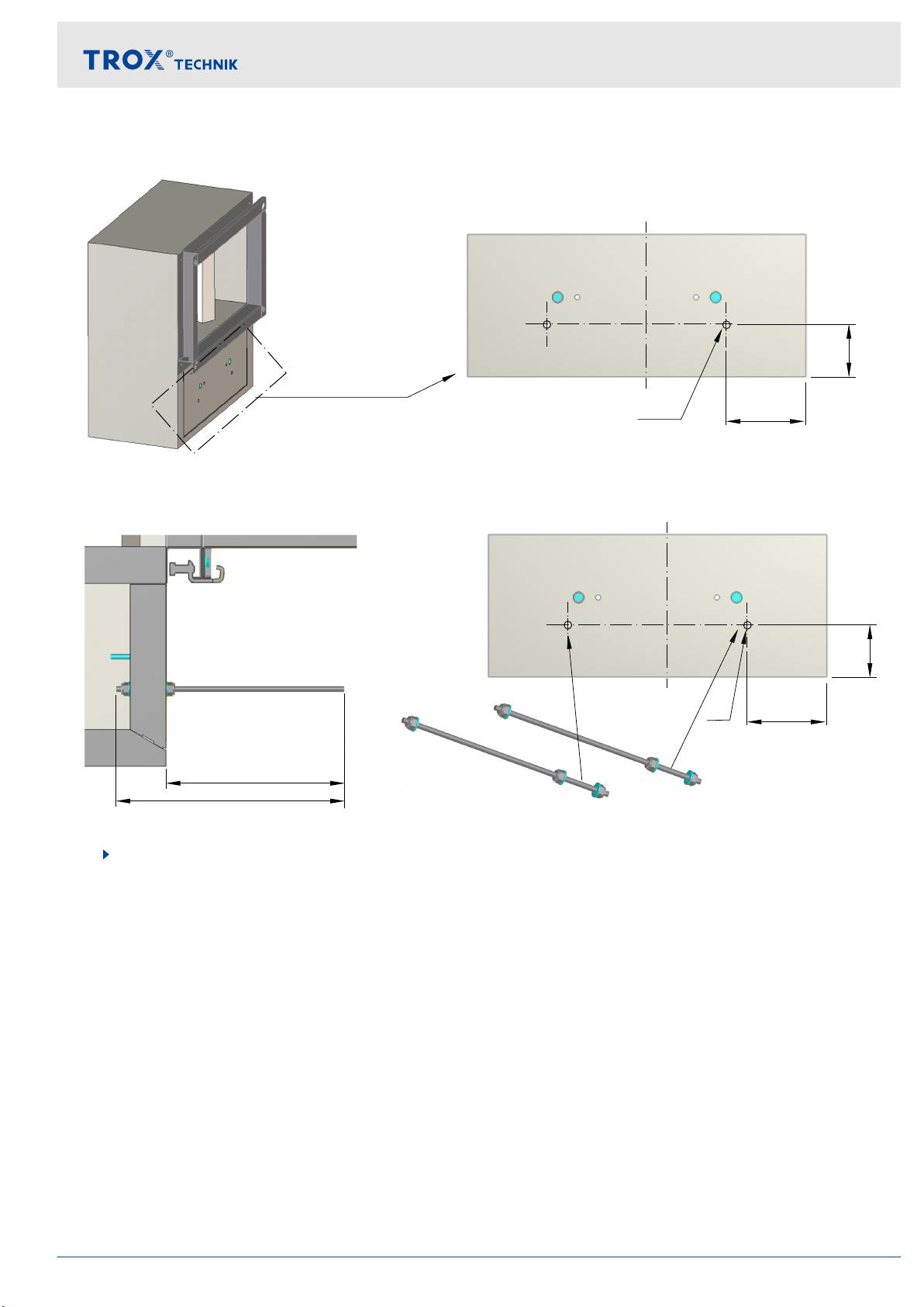
∅9
65
100
Fig. 18: Additional holes in the control panel lid
∅9
65
100
195
250
Fig. 19: M8 threaded rod, washer, nut
3. Drill 2 x Ø9 mm holes in the control panel lid
Install insulation retaining bolts and re-install control panel lid
Installation
Operating side
Connecting Frame EK-JZ – FF 19

Fig. 20: Infilling the Gaps
4. Infill all gaps between the duct insulation and the damper body with rockwool ensuring no gaps
Installation
Operating side
Connecting Frame EK-JZ – FF20
Table of contents
Other Trox Technik Industrial Equipment manuals

Trox Technik
Trox Technik X-AIRCONTROL FAM-RD User manual

Trox Technik
Trox Technik TFCU Series Specification sheet

Trox Technik
Trox Technik TVRK User manual

Trox Technik
Trox Technik FKT-EU User manual

Trox Technik
Trox Technik CFE User manual

Trox Technik
Trox Technik QL-WF-EO User manual

Trox Technik
Trox Technik JS User manual
Popular Industrial Equipment manuals by other brands


schmersal
schmersal AZM201Z-SK-T-1P2PW-A-DU instructions

schmersal
schmersal AZM201Z-I2-CC-T-1P2PW Instructions for operation

Bosch
Bosch rexroth Sytronix SvP 7020 PFC 03 operating instructions

AIRSLED
AIRSLED MP3400 owner's manual

Rockwell Automation
Rockwell Automation Allen-Bradley 194U Series installation instructions

Wey
Wey MF instruction manual