Zero BNP-160 User manual

NOTICE TO PURCHASERS AND USERS OF OUR
PRODUCTS AND THIS INFORMATIONAL MATERIAL
Clemco proudly provides products for the abrasive blast industry
and is confident that industry professionals will use their knowledge
and expertise for the safe and efficient use of these products.
The products described in this material, and the information
relating to these products, are intended for knowledgeable,
experienced users. It is the responsibility of the user to insure that
proper training of operators has been performed and a safe work
environment is provided.
No representation is intended or made as to: the suitability of the
products described here for any purpose or application, or to the
efficiency, production rate, or useful life of these products. All
estimates regarding production rates or finishes are the
responsibility of the user and must be derived solely from the user’s
experience and expertise, not from information contained in this
material.
It is possible that the products described in this material may be
combined with other products by the user for purposes determined
solely by the user. No representations are intended or made as to
the suitability of or engineering balance of or compliance with
regulations or standard practice of any such combination of products
or components the user may employ.
This equipment is only one component of a cabinet blasting
operation. Other products, such as air compressors, air filters and
receivers, abrasives, equipment for ventilating, dehumidifying, or
other equipment, even if offered by Clemco, may have been
manufactured or supplied by others. The information Clemco
provides is intended to support the products Clemco manufactures.
Users must contact each manufacturer and supplier of products
used in the blast operation for warnings, information, training, and
instruction relating to the proper and safe use of their equipment.
BNP-160 TUMBLE BASKET
SUCTION BLAST CABINET
O. M. 25993
DATE OF ISSUE: 03/13
REVISION: Rev. B, 05/18
© 2018 CLEMCO INDUSTRIES CORP.
One Cable Car Dr.
Washington, MO 63090
Phone (636) 239-4300
Fax (800) 726-7559
www.clemcoindustries.com

BNP-160 TUMBLE BASKET BLAST CABINET Page 1
© 2018 CLEMCO INDUSTRIES CORP. www.clemcoindustries.com Manual No. 25993 Rev B 05/18
1.0 INTRODUCTION
1.1 Scope of Manual
1.1.1 These instructions cover setup, operation,
maintenance, troubleshooting, optional accessories, and
replacement parts for the BNP-160 Tumble Basket Blast
Cabinet.
1.1.2 These instructions contain important information
required for safe operation of the cabinet. Before using
this equipment, all personnel associated with the blast
cabinet operation must read this entire manual and all
accessory manuals to become familiar with the
operation, parts, and terminology.
1.2 Safety Alerts
1.2.1 Clemco uses safety alert signal words, based on
ANSI Z535.4-2011, to alert the user of a potentially
hazardous situation that may be encountered while
operating this equipment. ANSI's definitions of the signal
words are as follows:
This is the safety alert symbol. It is used
to alert you to potential physical injury
hazards. Obey all safety messages that
follow this symbol to avoid possible
injury or death.
NOTICE
Notice indicates information that is considered
important, but not hazard-related, if not
avoided, could result in property damage.
CAUTION
Caution indicates a hazardous situation that, if
not avoided, could result in minor or moderate
injury.
WARNING
Warning indicates a hazardous situation that, if
not avoided, could result in death or serious
injury.
DANGER
Danger indicates a hazardous situation that, if
not avoided, will result in death or serious
injury.
1.3 Table of Contents
SUBJECT SECTION LOCATION
INTRODUCTION ........................................................1.0
Scope of Manual .........................................................1.1
Safety Alerts ...............................................................1.2
Table of Contents .......................................................1.3
General Description ....................................................1.4
Theory of Operation ....................................................1.5
Dust Collector .............................................................1.6
Nozzle Options ...........................................................1.7
Tumble Basket Options ..............................................1.8
Media ..........................................................................1.9
Compressed Air Requirements ................................1.10
Electrical Requirements ............................................1.11
INSTALLATION ......................................................... 2.0
General Installation Notes .......................................... 2.1
Connect Compressed Air-Supply Line ....................... 2.2
Ground Cabinet .......................................................... 2.3
Plug Power Cord into 115-VAC Outlet ........................ 2.4
OPERATION .............................................................. 3.0
Control Functions ........................................................ 3.1
Media Loading and Unloading .................................... 3.2
Loading and Unloading Parts ..................................... 3.3
Blasting Operation ...................................................... 3.4
Stop Blasting ............................................................... 3.5
ADJUSTMENTS ......................................................... 4.0
Blasting Pressure ........................................................ 4.1
Pulse Pressure ........................................................... 4.2
Timer, Blast Duration .................................................. 4.3
Door Interlock ............................................................. 4.4
Inlet Damper ............................................................... 4.5
Adjustable Door Slide, Reclaimer................................ 4.6
Dust Collector Pulse, Pulse Valve/Cam Follower ....... 4.7
Preventive Maintenance ........................................... 5.0
Daily Maintenance ...................................................... 5.1
Weekly Maintenance .................................................. 5.2
Monthly Maintenance ................................................. 5.3
Additional Cartridge Pulsing ....................................... 5.4
Service Maintenance ................................................ 6.0
Gun and Nozzle Assembly ......................................... 6.1
Tumble Basket ............................................................ 6.2
Filter Cartridge Replacement ...................................... 6.3
Seasoning Cartridge ................................................... 6.4
Inline Filter, Differential Pressure Gauge ................... 6.5
Tube-Lock Fittings ....................................................... 6.6
Replace Reclaimer Wear Plate .................................. 6.7

BNP-160 TUMBLE BASKET BLAST CABINET Page 2
© 2018 CLEMCO INDUSTRIES CORP. www.clemcoindustries.com Manual No. 25993 Rev B 05/18
Troubleshooting ........................................................7.0
Dust Leaking from Cabinet Enclosure .........................7.1
Abnormally High Media Consumption .........................7.2
Reduction in Blast Cleaning Rate ...............................7.3
Plugged Nozzle ...........................................................7.4
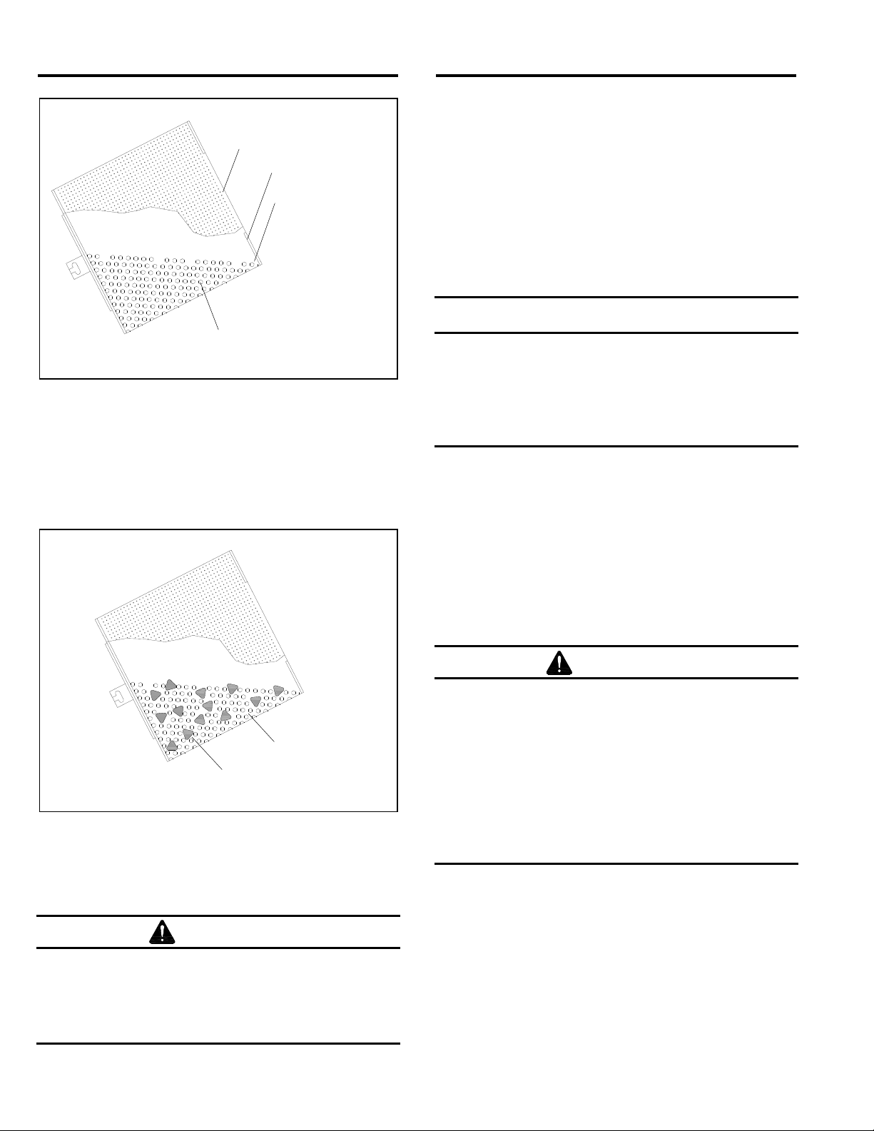
Media Bridging ............................................................7.5
Neither Media Nor Air Comes Out the Nozzle
During Blast Cycle ....................................................7.6
Blockage in Media Hose ..............................................7.7
Poor Suction in Media Hose ........................................7.8
Air Only (no media) from Nozzle .................................7.9
Blowback through Media Hose .................................7.10
Media Buildup in Cabinet Hopper, Media Does
Not Convey to Reclaimer .......................................7.11
Static Shocks .............................................................7.12
Dust Leaking from Dust Collector Door......................7.13
Dust Leaking from Exhaust Muffler ...........................7.14
Dust Collector Not Pulsing ........................................7.15
Pulse is Steady Stream of Air
Instead of Quick Pulse ...........................................7.16
Exhauster Not Running .............................................7.17
High Reading on Differential Pressure Gauge ..........7.18
No or Low Reading on Differential Pressure Gauge 7.19
Accessories and Replacement Parts ......................8.0
Optional Accessories ...................................................8.1
Electrical Components ............Refer to Elect. Schematic
Cabinet and Exhauster Assembly ...............................8.2
Basket and Drive Assembly ........................................8.3
Gun, Media Feed, and Plumbing Assembly ................8.4
Reclaimer Assembly ....................................................8.5
Dust Collector Assembly .............................................8.6
Dust Collector Pulse and Plumbing .............................8.7
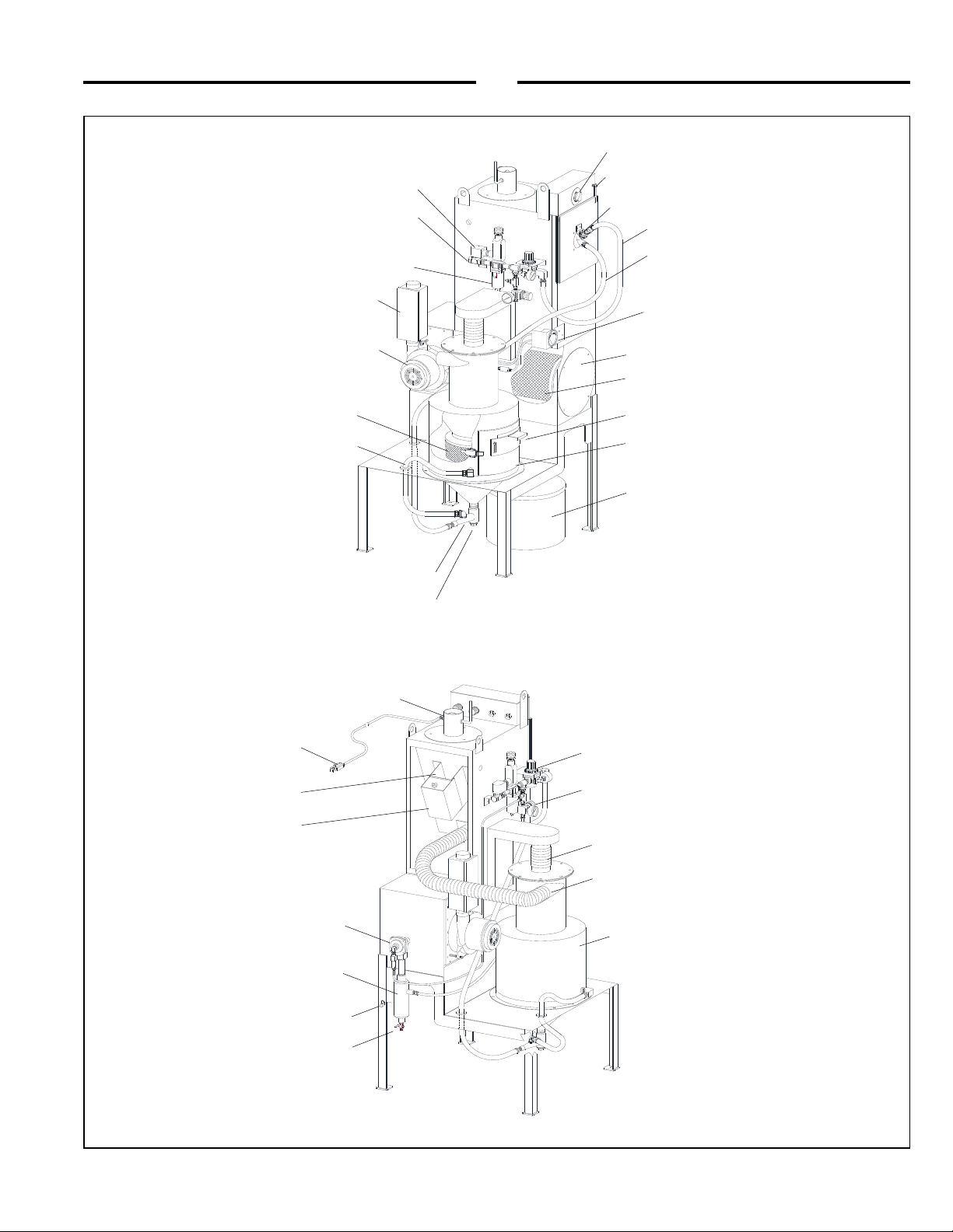
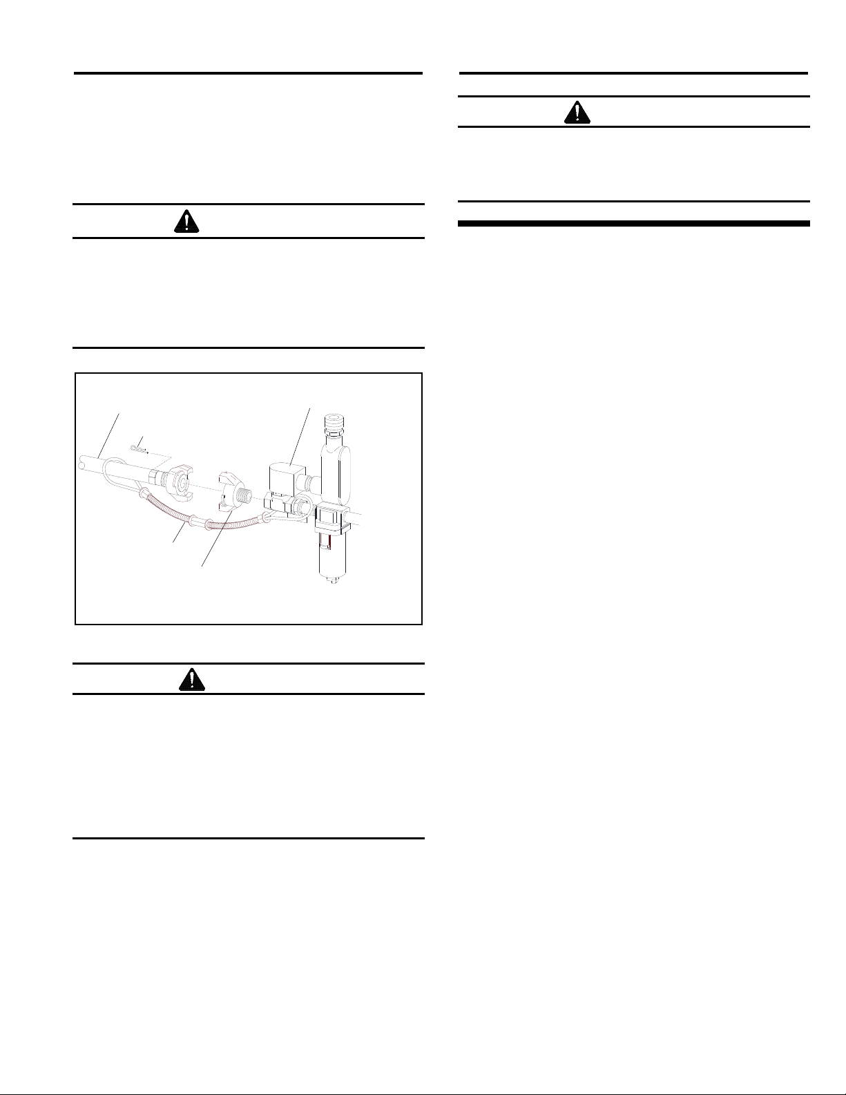
1.4 General Description
1.4.1 The BNP-160 tumble cabinet blasts small
batches of parts using a fixed nozzle and rotating
basket. Refer to Figure 1 for arrangement and callouts of
primary components. The cabinet consists of three major
segments:
1. Cabinet enclosure
2. Reclaimer
3. Reverse-pulse dust collector
1.4.2 The maximum capacity of the basket is 25 lbs.
1.4.3 The cabinet requires approximately 33 cfm of
compressed air at a maximum of 80 psi.
1.5 Theory of Operation
1.5.1 After parts are loaded into the basket, the air
supply and exhauster are turned ON, and the cabinet door
is closed, the cabinet is then ready for operation by setting
the timer located in the control box atop the cabinet
enclosure. Turn the dial to set the blast duration between
1 minute and 60 minutes. Blasting begins once the timer
is set. Air moving through the gun draws media into the
blast gun mixing chamber. The media mixes with the air
and is propelled out the nozzle. As the basket rotates, the
parts tumble in the blast stream, ensuring that all parts
and surfaces are uniformly blasted. The blast media
flows through the perforated drum and into the cabinet
hopper. These particles are drawn into the reclaimer for
separation. First dust and fines are separated from the
reusable blast media. Reusable media is retained in the
reclaimer hopper for reuse. Then dust and fines are drawn
out of the reclaimer and through the filter cartridge in the
reverse-pulse dust collector. The filter cartridge traps dust
on the outer surface and discharges clean air through the
outlet damper atop the collector. The filter cartridge is
cleaned by a pulse of high-velocity compressed air
expanding against the inner surface of the cartridge at
regular intervals. The expanding air momentarily reverses
airflow through the cartridge to release dust accumulated
on the outer surface. The dust particles fall away from the
cartridge and into the hopper and dust container for
removal. Blasting automatically stops when the timed cycle
is completed.
1.6 Dust Collector
1.6.1 The BNP-160 cartridge dust collector is not
suitable for use in applications that generate dust from
lead coatings, heavy metals, or any other toxic materials.
WARNING
Prolonged exposure to any dust can result in
serious lung disease and death. Short-term
ingestion of toxic materials, such as lead dust
or dust from other heavy metals and
corrosives, can cause serious respiratory injury
or death. This machine is not to be used in
applications which generate dust from lead
coatings, heavy metals or any other toxic
materials. Identify all materials that are to be
removed by blasting and obtain a safety data
sheet (SDS) for the blast media.
1.7 Nozzle Options
1.7.1 Ventilation requirements limit standard cabinets
to No. 5 (5/16" orifice) nozzle and No. 5 (5/32" orifice) air
jet. Unless otherwise specified at the time of order,
cabinets are supplied with a tungsten carbide lined
nozzle. Ceramic nozzle are available but should be
limited to occasional blasting and with mild media. More
durable boron carbide nozzles should be used when
blasting with aggressive media such as those listed in
Section 1.9.4. Nozzle options are shown under Gun,
Media Feed, and Plumbing Assembly in Section 8.4.

BNP-160 TUMBLE BASKET BLAST CABINET Page 3
© 2018 CLEMCO INDUSTRIES CORP. www.clemcoindustries.com Manual No. 25993 Rev B 05/18
Figure 1
Some items are removed
or rotated for clarity.
Motor Cove
r
Adjustable Door Slide
Blast Gun Assembl
y
Media Hose
Exhauste
r
Filter Cartridge
Com
p
ressed Air Filte
r
Door Interlock Switch
Timer Control
Metering Valve
Blast Gun Air Hose
Media Drain Plug
Exhaust Muffle
r
Compressed Air Inlet
(Air hose attachment point)
Filter Cartridge Access Door
Differential Pressure Gauge
(For dust collector filter cartridge)
Media Vent Hose
Dust Container
Reclaimer Storage Access Door,
Media Fill Doo
r
Debris Screen
Inlet-Solenoid Valve
Blast-Pressure Regulator
Grounding Bolt
Pulse Reservoir
Pulse Valve
120-Volt U-Ground Plug
Inlet Damper
Pulse-Pressure Regulator
Reclaimer Inlet
Reclaimer Media Storage Section
Reclaimer Outlet
Motor Mount Bracket
Drain Petcock

BNP-160 TUMBLE BASKET BLAST CABINET Page 4
© 2018 CLEMCO INDUSTRIES CORP. www.clemcoindustries.com Manual No. 25993 Rev B 05/18
1.8 Tumble Basket Options
1.8.1 Standard baskets are perforated with 3/16"
holes. An optional basket with 1/16" holes is offered for
use with fine abrasive or applications that produce small
chips or other byproducts that could plug the blast
nozzle. Refer to basket and drive assembly replacement
parts om Section 8.3.
1.9 Media
1.9.1 The BNP-160 utilizes most common reusable
media 60 mesh to 180 mesh that is specifically
manufactured for dry blasting. Media finer than those
recommended may carry over to the dust collector.
Media coarser than those recommended may not
convey through the media hose or recovery hose.
1.9.2 Steel: Steel grit 50 mesh to 120 grit or S70 to
S170 shot may be used.
1.9.3 Sand and slag media These are not suitable for
cabinet use. Sand should NEVER be used for abrasive
blasting because of the respiratory hazards associated
with media containing free silica. Slags are not
recommended because they rapidly break down and are
not recyclable.
1.9.4 Aluminum Oxide, Silicon Carbide, and
Garnet: These are the most aggressive of the commonly
used media. Aggressive media such as these between
60 mesh and 180 mesh may be used, but the service life
of any components exposed to the media will be
reduced. To avoid unscheduled downtime and maximize
cabinet life, periodically inspect all parts of the cabinet,
basket, nozzle, and hoses, that come in contact with the
media. Boron carbide lined nozzles are recommended
when using aggressive media.
1.9.5 Glass Bead Recommended range is #6 thru
#13: Most beads are treated to ensure free-flow
operation even under moderately high humidity
conditions. Glass beads subjected to excessive moisture
may be reused after thorough drying and breaking up of
any clumps.
1.9.6 Fine-Mesh Media: In most cases media finer
than 180 will carry over to the dust collector.
1.9.7 Lightweight Media: Plastic and similar
lightweight and/or nonaggressive media are generally
not recommended for suction-style cabinets because the
lower blast velocity of suction blasting combined with the
softer and lighter weight media do not provide the media
impact for productive blasting.
1.10 Compressed Air Requirements
1.10.1 The cabinet requires approximately 33 cfm of
compressed air at a maximum of 80 psi.
1.10.2 The filter at the air inlet connection reduces
condensed water from the compressed air. Its use is
especially important in areas of high humidity, or when
fine-mesh media are used. Moisture causes media to
clot and inhibits free flow through the feed assembly. If
the filter does not remove enough moisture to keep
media dry and flowing, it may be necessary to install an
air dryer or aftercooler in the air-supply line.
1.11 Electrical Requirements
1.11.1 The system requires 115 VAC, 1 PH, 60 Hz,
with 15 amps service. A 7-foot power cord is supplied.
No additional wiring is required.
WARNING
Do not use electrical adaptors that eliminate the
ground prong on 115-volt plugs. Doing so can
cause injury from electric shock and damage
equipment.
2.0 INSTALLATION
2.1 General Installation Notes
2.1.1 Place the cabinet in a convenient location where
compressed air and electrical service are available.
Allow full access to the doors and service areas.
2.2 Connect Compressed Air-Supply Line
WARNING
Failure to observe the following before
connecting the equipment to the compressed
air source could cause serious injury or death
from the sudden release of compressed air:
Lockout and tagout the compressed air
supply.
Bleed the compressed air-supply line.
2.2.1 Refer to Figure 2 and apply thread sealant to the
male threads of an air fitting that is compatible with the
air-supply hose fitting, and install it onto the 1/2" NPT

BNP-160 TUMBLE BASKET BLAST CABINET Page 5
© 2018 CLEMCO INDUSTRIES CORP. www.clemcoindustries.com Manual No. 25993 Rev B 05/18
inlet solenoid located on the side of the cabinet. The
style of connection shown in Figure 2 is for reference
only. The air line may also be hard piped.
2.2.2 Connect a 1/2" ID or larger air line from the air
source to the air fitting, as shown in Figure 2.
WARNING
To avoid the risk of injury from compressed air,
install an isolation valve and bleed-off valve
where the air supply is tapped into the
compressed air source. This enables
depressurization of the compressed-air line
before performing maintenance.
Figure 2
WARNING
Hose disconnection while under pressure could
cause serious injury or death. Use safety lock
pins or safety wire to lock twist-on couplings
together and prevent accidental separation, and
also use safety cables to prevent hose from
whipping should separation occur. Safety lock
pins and safety cables are listed in Section 8.1:
Optional Accessories.
2.3 Ground Cabinet
2.3.1 To prevent static electricity buildup, attach an
external grounded wire from an earth ground to the
grounding bolt on the rear of the cabinet.
2.4 Plug the cabinet power cord into a grounded,
115-volt outlet.
WARNING
Do not use electrical adaptors that eliminate the
ground prong on 115-volt plugs. Doing so can
cause injury from electric shock and damage
equipment.
3.0 OPERATION
3.1 Control Functions
3.1.1 Timer: Sets duration of the blast cycle up to 60
minutes. Blasting begins as soon as the timer is set.
Blasting automatically stops when the timed cycle is
complete.
3.1.2 Door Interlock: When the door is open, the
blast gun is disengaged, preventing blasting.
3.2 Media Loading and Unloading
3.2.1 Media Loading: With the timer off, add clean
dry media by pouring it through the reclaimer access
door. Do not fill above the storage section’s cone.
3.2.2 Media Unloading: To empty the cabinet and
reclaimer of spent media, allow all media to be
recovered from the cabinet, turn off the exhauster, and
place an empty container under the media-metering
valve located under the reclaimer storage section.
Unscrew the plastic plug, permitting media to flow into
the container. If media does not flow, it has caked. Open
the fill door and stir media until it starts to flow. Replace
the drain plug when the storage section is empty.
3.2.3 When changing media type, use a vacuum and
thoroughly purge the cabinet of media, especially when
changing from coarse media to fine or when changing
from hard media to soft.
3.3 Loading and Unloading Parts
3.3.1 Parts must be free of oil, water, grease, or other
contaminants that will cause media to clump or
contaminate parts.
3.3.2 Unlatch and open the front door and load parts
directly into the tumble basket. Do not overload the
basket; maximum load should not exceed 25 lb or the
bottom edge of the retainer, as shown in Figure 3.
Safety Lock Pin
Safet
y
Cable
Air-Supply Hose
Air Fitting
Inlet Solenoid

BNP-160 TUMBLE BASKET BLAST CABINET Page 6
© 2018 CLEMCO INDUSTRIES CORP. www.clemcoindustries.com Manual No. 25993 Rev B 05/18
Figure 3
3.3.3 Do not underload with parts; underloading will
result in rapid wear to the tumble basket. When blasting
small loads, to prevent the blast stream from blasting the
basket, add filler material (dunnage), as shown in Figure
4, such as an abrasive-resistant tumble media that is
compatible with the parts being blasted.
Figure 4
3.3.4 Close door and latch securely.
3.4 Blasting Operation
WARNING
To avoid hazardous dust leakage and
equipment malfunction:
Keep door closed during blasting.
Stop blasting immediately if dust leaks
are detected.
3.4.1 Slowly open the air valve on the air-supply hose
to the cabinet. Check for air leaks on the initial start up,
and periodically thereafter.
3.4.2 Adjust the blast-pressure regulator located on
the side of the cabinet to the required blast pressure per
Section 4.1.
3.4.3 Adjust the pulse-pressure regulator located on
the side of the cabinet to the required pulse pressure per
Section 4.2.
NOTICE
Do not pulse new dust collectors or
replacement cartridges until the cartridge is
properly seasoned. Refer to Section 6.4.
Pulsing unseasoned cartridges can cause
premature cartridge failure or decrease the
efficiency of the dust collector.
3.4.4 Load media and parts. Note load limit in Figure 3.
3.4.5 Close the cabinet door. Make sure the door is
latched securely, or door interlock system will prevent
blasting.
3.4.6 Start the blast cycle by turning the timer for the for
the blast duration, between 1 and 60 minutes. Blasting
begins as soon as the timer is set.
WARNING
Shut down the cabinet immediately if dust
discharges from the cabinet or dust collector.
Prolonged breathing of any dust can result in
serious lung disease. Short-term ingestion of
toxic dust such as lead poses an immediate
danger to health. Toxicity and health risk vary
with type of media and dust generated by
blasting. Identify all material being removed by
blasting and obtain a safety data sheet (SDS)
for the blast media.
3.5 Stop Blasting
3.5.1 Blasting, basket rotation, and the exhauster stop
when the timer cycle is completed.
3.5.2 Open the door only enough to disengage the
door interlock, and turn the timer ON to start the
exhauster. Let it run for several seconds to clear
airborne dust, then turn the switch OFF.
Load Limit
Do not load parts
above bottom edge
of retainer.
Retainer
Tumble Basket
Parts
Filler Material
Parts

BNP-160 TUMBLE BASKET BLAST CABINET Page 7
© 2018 CLEMCO INDUSTRIES CORP. www.clemcoindustries.com Manual No. 25993 Rev B 05/18
3.5.3 Remove parts and check blast coverage.
3.5.4 Reload additional parts, or when finished
blasting, shut off the air-supply valve and drain the air
filter and dust collector pulse reservoir.
4.0 ADJUSTMENTS
4.1 Blasting Pressure ‒Figure 5
4.1.1 The blast-pressure regulator located in the
piping on the side of the cabinet is used to adjust
blasting pressure to suit the application. The maximum
recommended pressure is 80 psi. Lower pressure may
be used for delicate work. Higher pressure may cause
dust or media to escape from the cabinet.
4.1.2 To adjust, unlock the knob by pulling it out and
turn it clockwise to increase pressure or counter-
clockwise to decrease pressure. Pressure will usually
drop from closed-line pressure when blasting begins.
Once operating pressure is set, push the knob in to lock
it and maintain the setting.
Figure 5
4.2 Pulse Pressure ‒Figure 6
NOTICE
Do not pulse new dust collectors or
replacement cartridges until the cartridge is
properly seasoned. Refer to Section 6.4.
Pulsing unseasoned cartridges can cause
premature cartridge failure or decrease the
efficiency of dust collector.
4.2.1 The pulse-pressure regulator, located in the
piping below the blast-pressure regulator, is used to
adjust pressure of the dust collector pulse. After the
cartridge is seasoned, set the pulse pressure to 40 psi.
When differential pressure reaches 8 inches (as noted
on the differential pressure gauge), do additional pulsing
as noted in Section 5.4 and increase pulse pressure by
10 psi. Continue to do additional pulsing and increase
pressure by 10 psi when differential pressure reaches 8
inches until the maximum of 80 psi is reached. Replace
the cartridge when 80 psi does not lower pressure below
8 inches or sooner if media recovery is impaired.
4.2.2 To adjust, unlock the knob by pulling it out, as
shown in Figure 6 and turn it clockwise to increase
pressure or counterclockwise to decrease pressure.
Once pressure is set, push the knob in to lock it and
maintain the setting.
Figure 6
4.3 Timer, Blast Duration
4.3.1 Turn the timer dial to set the timer for the
duration of the blast cycle. Blasting begins when the
timer is set and automatically stops when the timed cycle
ends. Trial and error will determine the timer setting for
the most favorable results. After the part is correctly
processed, make a note of the total blast time for future
runs of similar parts.
Blast-Pressure Regulator
Turn counterclockwise
to decrease pressure.
Turn clockwise to
increase pressure.
Push Knob in to lock it.
Pull knob out to unlock
and ad
j
ust
p
ressure.
Blast-Pressure
Regulator Knob
Turn counterclockwise
to decrease pressure.
Turn clockwise to
increase pressure.
Push Knob
in to lock it.
Pull knob out to
unlock and
adjust pressure.

BNP-160 TUMBLE BASKET BLAST CABINET Page 8
© 2018 CLEMCO INDUSTRIES CORP. www.clemcoindustries.com Manual No. 25993 Rev B 05/18
4.4 Door Interlock, Refer to Figure 7
WARNING
Never attempt to override the interlock system.
Doing so can result in injury from unexpected
blasting.
Figure 7
4.4.1 The door interlock disables the blasting control
circuit when the door is open. To enable blasting, the
door interlock switch must be engaged when the door is
closed. The interlock is set at the factory and does not
usually require field adjustment unless parts are
replaced. When adjustment is required, proceed as
follows:
4.4.1.1 Close cabinet door.
4.4.1.2 Loosen the adjusting screw nut.
4.4.1.3 Center the adjusting screw on the switch and
turn it in or out as required to engage the switch without
applying excessive pressure. Tighten the adjusting
screw nut to secure.
4.4.1.4 Test the operation with the door open only
enough to disengage the interlock switch, and then
again with the door closed. The interlock should stop the
blasting when the door is opened and permit blasting
when the door is closed.
4.5 Inlet Damper ‒Figure 8
4.5.1 Operate with the damper fully open. A closed or
partially closed damper will reduce air movement
through the cabinet and can cause dust leaks from
cabinet or media buildup in cabinet.
Figure 8
4.6 Adjustable Door Slide, Reclaimer Storage
Section ‒Figure 9
4.6.1 The door slide is adjustable from fully closed to
various degrees of open. The adjustment controls the
amount of fines that are retained or removed from
recycled media. When the slide is closed, no ambient air
enters the reclaimer and finer media is retained. As the
slide is gradually opened ambient air is drawn in,
drawing out fines into the dust collector. The further the
slide is opened, the more air is drawn in, which pulls out
larger particles of spent media.
4.6.2 Begin with the slide closed.
Figure 9
4.6.3 To Remove More Fines: (Too much dust in
media.) Loosen the wing nuts and lower the door by no
more than 1/16" increments. It may take a few cycles to
remove the fines; allow the media to go through several
cycles before further adjustment. Lower the door to
remove more fines; raise the door to retain more media.
Door Slide
Opening for
ambient air flow
Wing Nut
Interlock Switch
Cabinet Door
Adjusting Screw
(Adjust the screw to engage the
switch when door is closed.)
Nut
Inlet Damper’
(Shown fully open.)

BNP-160 TUMBLE BASKET BLAST CABINET Page 9
© 2018 CLEMCO INDUSTRIES CORP. www.clemcoindustries.com Manual No. 25993 Rev B 05/18
The following are examples of the door slide setting
during factory tests:
1) #13 glass beads – slotted door shut
2) #8 glass beads – slotted door open about 3/16"
3) #11 glass beads – slotted door open about 3/32"
4) 180 mesh aluminum oxide – slotted door open
about 3/32"
5) 80 mesh aluminum oxide – slotted door open about
1/8"
4.6.4 To Remove Less Fines: (Too much good
media carried over to the dust collector.) Loosen the
wing nuts and raise the door by no more than 1/16"
increments.
4.7 Dust Collector Pulse,
Pulse Valve/Cam Follower ‒Figure 10
4.7.1 The pulse activating mechanism is located
within the motor mount bracket.
4.7.2 The dust collector pulses once with each
revolution of the basket. When the screw on the split
collar rotates over the cam follower, it pushes in the
plunger on the 3-way pulse valve and triggers the pulse.
4.7.3 Loosen the collar setscrews and rotate the split
collar so the cam screw is riding on the cam follower.
Tighten the setscrews to secure the collar.
Some items are removed for clarity.
Figure 10
4.7.4 Loosen the mounting bracket screws and adjust
the height so the cam follower depresses the plunger on
the 3-way pulse valve. Snug the screws to hold the
bracket in place.
4.7.5 Set the blast-pressure regulator to zero psi and
set the pulse-pressure regulator to 40 psi.
4.7.6 Turn the timer dial to start the basket rotation.
4.7.7 The collector should pulse each time the cam
screw rides onto the cam follower and stop when the
screw rides off the follower.
4.7.8 Adjust the mounting bracket up or down until the
pulse functions accordingly. Tighten the mounting
screws to secure.
5.0 PREVENTIVE MAINTENANCE
WARNING
This machine is not to be used for applications
that generate dust from lead coatings, heavy
metals, or any other toxic materials. Failure to
wear approved respirators and eye protection
when servicing dust-laden areas of the cabinet
and dust collector, and when emptying the
container, can result in serious eye irritation and
lung disease. Toxicity and health risk vary with
type of media and dust generated by blasting.
The respirator must be approved for the type of
dust generated. Identify all material being
removed by blasting and obtain a safety data
sheet (SDS) for the blast media.
To avoid unscheduled downtime, establish a weekly
inspection schedule. Inspect all parts subjected to media
contact, including; nozzle, media hose, flex hose, wear
plate, and all items covered in this section.
5.1 Daily Maintenance
5.1.1 Check media level and condition of media: Refill
or change media as necessary.
5.1.2 Check reclaimer screen for debris: The screen is
accessible through the reclaimer door. With the
exhauster OFF, remove the screen and empty it daily
and when loading media. Empty the screen more often if
part blasted causes excessive debris. Do not operate the
machine without the screen in place, oversized
byproduct from blasting could plug the nozzle.
5.1.3 Drain compressed air filter ‒Figure 11: The
cabinet is equipped with a manual-drain air filter. Open
the drain at least daily; if water is present, open
periodically during operation. Moist air inhibits the flow of
media; if the filter does not remove enough moisture to
Screws
Setscrews
Mounting Bracket
Motor Mount
(Shown for reference.)
Basket Drive Shaft
(Shown for reference.)
Split Colla
r
3-Wa
y
Pulse Valve
Cam Scre
w
Cam Followe
r

BNP-160 TUMBLE BASKET BLAST CABINET Page 10
© 2018 CLEMCO INDUSTRIES CORP. www.clemcoindustries.com Manual No. 25993 Rev B 05/18
keep media dry and flowing, it may be necessary to
install an air dryer or aftercooler in the air-supply line.
Figure 11
5.1.4 Drain pulse reservoir ‒Figure 12. Open the
petcock to drain water from the pulse reservoir after
each use. If water is present, open periodically during
operation.
Figure 12
5.1.5 Inspect Dust Level and Empty Dust Container
NOTICE
Inspect dust level in the dust container each
time the collector is shut off and when adding
new media to the cabinet. Empty the dust
container when it is no more than half-full.
Failure to monitor the dust level will overfill the
collector, requiring extensive cleaning.
NOTE: Blast media is usually nontoxic, however,
materials removed by the blast process may be
toxic. Check with local authorities for disposal
restrictions.
5.1.5.1 Empty dust level and empty the dust container
regularly. Start by checking the container at least daily
and when adding media, then adjust frequency based on
usage, contamination, and friability of the media.
5.1.5.2 Turn off the exhauster and release the lid lock
ring from the dust container, as shown in Figure 13.
5.1.5.3 Pry off the lid from the container (the lid's flexible
inlet hose allows easy removal) and remove the
container.
Figure 13
5.1.5.4 Tie off or otherwise seal the top of the liner and
remove it from the container. Dispose of the sealed liner
into a suitable disposal receptacle.
5.1.5.5 Place a new liner inside the container and drape
it over the top edge. Reattach the container to the lid and
latch the lock ring, making sure the lid and clamp are
secure. Replacement liners are shown in Section 8.6,
Figure 23, Item 28.
Pulse Reservoi
r
Drain Petcock
Inlet Solenoid
Compressed Air Filte
r
Manual Drain
Drum Liner
Latch
Latch Catch
Swing the catch
up to unlock the
lock-ring latch.
Pull the latch
away from the
ring and remove
the ring.

BNP-160 TUMBLE BASKET BLAST CABINET Page 11
© 2018 CLEMCO INDUSTRIES CORP. www.clemcoindustries.com Manual No. 25993 Rev B 05/18
5.2 Weekly Maintenance
5.2.1 Inspect nozzles and gun bodies for wear as
noted in Section 6.1, Replace nozzle when orifice
diameter is worn 1/16" larger than original size or when
suction diminishes noticeably.
5.2.2 During operation, inspect cabinet door seals for
media leaks.
5.2.3 Inspect flex hoses for wear.
5.2.4 Inspect the media hose for thin spots by
pinching it every 6 to 12 inches. Replace the hose when
it becomes soft.
5.3 Monthly Maintenance
5.3.1 Inspect reclaimer wear plate for wear. Replace
as necessary.
5.3.2 Inspect reclaimer door gasket for wear or
damage.
5.3.3 Inspect the tumble basket’s bottom liner for
wear. Replace the liner per Section 6.2 as soon as the
liner is worn thin and before wearing through to the
bottom plate.
5.4 Additional Cartridge Pulsing
5.4.1 The cartridge is pulsed with each revolution of
the basket. Additional pulsing should be performed as
noted below before adjusting the pulse pressure:
5.4.1.1 Turn blast pressure to 0 psi.
5.4.1.2 Turn exhauster ON.
5.4.1.3 Set timer to five minutes.
5.4.1.4 After the five minute cycle is complete, check
the differential pressure gauge. If differential pressure
stays at around 8 inches, increase pulse pressure by 10
psi increments as noted on Section 4.2.
5.4.1.5 Repeat the process once or twice.
6.0 SERVICE MAINTENANCE
WARNING
This machine is not to be used for applications
that generate dust from lead coatings, heavy
metals, or any other toxic materials. Failure to
wear approved respirators and eye protection
when servicing dust-laden areas of the cabinet
and when emptying the dust container can
result in serious eye irritation and lung disease.
Toxicity and health risk vary with type of media
and dust generated by blasting. The respirator
must be approved for the type of dust
generated. Identify all material being removed
by blasting and obtain a safety data sheet (SDS)
for the blast media.
6.1 Gun and Nozzle Assembly
6.1.1 Open the cabinet door, unscrew the holding nut
from the gun end, and pull the nozzle from the gun.
6.1.2 Inspect the gun body, nozzle, orifice, and 1/4"
NPT nipple for wear. Replace any that are worn or
damaged. Replace the nozzle when its orifice diameter
has increased to 3/8" (increased by 1/16" larger than
when new), or when suction diminishes noticeably.
6.1.3 When installing the nozzle, insert the tapered
end into the gun placing the tapered end toward the jet.
Screw the holding nut onto the gun.
6.2 Tumble Basket
6.2.1 Periodically inspect the basket and bottom liner
for wear.
6.2.2 The bottom liner is held to the bottom of the
basket by the two support ribs; remove the liner by
peeling it from the bottom and from under the ribs.
6.2.3 Replace the liner in reverse order, tucking the
edge under the support ribs.
6.2.4 Replace the basket as soon as it is worn thin.

BNP-160 TUMBLE BASKET BLAST CABINET Page 12
© 2018 CLEMCO INDUSTRIES CORP. www.clemcoindustries.com Manual No. 25993 Rev B 05/18
6.3 Filter Cartridge Replacement
Figures 14 and 15
WARNING
Failure to wear approved respirators and eye
protection when servicing dust-laden areas of
the cabinet and dust collector, and when
changing the filter cartridge, can result in
serious eye irritation and lung disease or death.
6.3.1 Close the air-supply valve and bleed all air from
the pulse reservoir.
6.3.2 Remove the four wing nuts and washers
securing the cover plate and remove the cover plate.
Figure 14
6.3.3 Remove the nut, lock washer, flat washer, and
rubber gasket from the cartridge support, as shown in
Figure 15. Remove the cartridge through the opening,
sliding it off the support. NOTE: Contain dust by
sliding a durable plastic bag over the cartridge as it
is removed.
Figure 15
6.3.4 After the cartridge is removed, clean the inside
of the collector to remove loose dust or hardened dust
clumps, particularly from the cartridge sealing surface
(front side of the cartridge sheet).
6.3.5 A new rubber gasket comes with the new
cartridge. Use the new gasket, reuse the fasters, and
install the cartridge in reverse order.
6.3.6 Inspect the cover gasket for any condition that
will prevent the gasket from sealing. Replace the gasket
if necessary.
6.3.7 Install the cover plate and secure.
6.3.8 Season cartridge per Section 6.4.
6.4 Seasoning Cartridge
6.4.1 New cartridge must be seasoned. Cartridges are
seasoned by not pulsing them until a dust cake develops
on the filter media.
6.4.2 To prevent cartridge pulsing, turn the pulse
regulator off (to 0 psi).
6.4.3 Operate the cabinet without pulsing until the
differential pressure gauge reaches 2 inches. At that time,
turn the pulse regulator to 40 psi to start the pulsing cycle.
Refer to Section 4.2 to adjust pulse pressure.
6.5 Inline Filter, Differential Pressure Gauge
Figure 16
6.5.1 Periodically inspect the inline filter for dust. Dust
collects on the outer surface of the element.
6.5.2 To remove the dust and clean the element, turn
the inlet end cap toward O, as stamped on the cap, and
then pull the cap from the clear housing. NOTE: Only
the inlet cap opens. Refer to Section 6.6 if the tubing
needs to be removed.
Figure 16
Filter Cartridge
Flat Washer
Wing Nut
Cover Plate
Lock Washer
Gasket
Dust Collector
Rubber Gasket
Filter Cartridge
Nut
Lock Washer
Flat Washer
Some items removed
for clarity.
Differential Pressure Gauge
Lo (-) Pressure Port
Filter Element
Hi (+) Pressure Port
Turn toward
L to lock.
Turn toward
O to o
p
en.
Directional arrow points
toward differential pressure
gauge.

BNP-160 TUMBLE BASKET BLAST CABINET Page 13
© 2018 CLEMCO INDUSTRIES CORP. www.clemcoindustries.com Manual No. 25993 Rev B 05/18
6.5.3 Remove the element and empty dust from the
housing.
6.5.4 Shake the cap and tubing to see if dust is in the
tubing. If dust is present, remove the tubing from the cap
and shake the tubing until all dust is removed.
NOTICE
If the inline filter is removed from the tubing,
reinstall it with the directional arrow pointing
toward the Hi (+) pressure port on the differential
pressure gauge, as shown in Figure 16.
6.5.5 Before attaching the inlet cap, be sure the filter
is correctly positioned. Align the tabs on the cap with the
recesses on the housing. Make sure the end of the cap
enters the ID of the element as it is pushed into position.
Turn the cap toward L to lock it in place.
6.6 Tube-Lock Fittings – Figure 17
WARNING
Failure to observe the following procedure
before performing any maintenance can cause
injury from the sudden release of trapped
compressed air.
Lock out and tag out the compressed air
supply.
Bleed all compressed air-supply lines.
6.6.1 To remove the tubing, push the retaining collar
toward the fitting, releasing the tubing so it can be easily
removed by pulling it out. Do not force it; only a slight
pull on the tubing is required if the collar is pushed in
correctly.
Figure 17
6.6.2 Reconnect the tubing by inserting it into the
retaining collar until it seats. Tug on the tubing to make
sure it is secured.
6.7 Replace Reclaimer Wear Plate – Figure 18
6.7.1 Remove the fasteners holding the reclaimer top
to the body and remove the top.
6.7.2 The gasket should adhere to the reclaimer when
the top is removed. Inspect the gasket and replace it if
damaged.
6.7.3 Remove the screws that hold the wear plate to
the body and remove the old wear plate.
6.7.4 Press or clamp the new wear plate into position
and use self-drilling screws inserting through the existing
screw holes to secure the wear plate.
6.7.5 Replace the top and secure with fasteners.
Figure 18
Retaining Collar
Push collar in to release tubing.
Pull tubing straight out.
To reconnect the tubing, push it into the
fitting until it bottoms out. Pull on the
tubing to make sure it is securely fastened.
Wear Plate
Gasket
Self-Drilling Screws
Reclaimer Top
Clamp
Shown for reference.

BNP-160 TUMBLE BASKET BLAST CABINET Page 14
© 2018 CLEMCO INDUSTRIES CORP. www.clemcoindustries.com Manual No. 25993 Rev B 05/18
7.0 TROUBLESHOOTING
WARNING
To avoid serious injury from the sudden release
of trapped compressed air, observe the
following when troubleshooting:
Turn off the air, and lockout and tagout the
air supply.
Bleed all compressed air supply lines.
7.1 Dust Leaking from the Cabinet Enclosure
7.1.1 Dirty filter cartridge reducing air flow through
cabinet. Check differential pressure gauge. Refer to
Sections 4.2 to adjust pulse pressure and Section 5.4 for
additional pulsing.
7.1.2 Damaged door gaskets. Inspect and replace
damaged gaskets.
7.1.3 Blast pressure too high. Maximum blast
pressure is 80 psi.
7.1.4 Blockage in flex hose between cabinet sump
and reclaimer inlet. Inspect hose for blockage.
7.1.5 Exhauster not operating. Make sure exhauster
motor is in operation. If it is not, have the motor and
circuit checked by a qualified electrician.
7.1.6 Inlet damper closed or partially closed. Damper
should be fully open.
7.2 Abnormally High Media Consumption
7.2.1 Door on reclaimer open or improper fit, or worn
door gasket. Air entering the reclaimer at this point will
cause media to be carried into the dust collector. DO
NOT operate unless all doors are closed.
7.2.2 Reclaimer slide door open. Refer to Section 4.6
to adjust slide door.
7.2.3 Media may be too fine or worn-out. Refer to
Section 1.9 for recommended media size.
7.2.4 Using friable media that rapidly breaks down.
7.2.5 Nozzle pressure too high for the media, causing
media to break down.
7.3 Reduction in Blast Cleaning Rate
7.3.1 Low media level reducing media flow. Check
media level; add or replace media as needed.
7.3.2 Reduced air pressure, which could be caused by
a malfunctioning pressure regulator, a dirty filter element
in the air filter, a partially closed air valve, a leaking air
line, or other air tools in use.
7.3.3 Blockage in media hose or gun. Refer to Section
7.4 and 7.7.
7.3.4 Kink or blockage in vent hose between metering
valve and reclaimer. Make sure hose is clear.
7.3.5 Worn gun parts such as nozzle or air jet. Inspect
and replace all worn parts.
7.3.6 Worn media hose. Check hose for leaks and soft
spots. Replace worn or damaged hose.
7.3.7 Moist media. Frequent bridges or blockage in
the area of the metering valve can be caused by
moisture. Refer to Section 7.6.
7.4 Plugged Nozzle
7.4.1 Remove nozzle and check for blockage from
foreign material. If the standard tumble basket allows
large particles to pass and block the nozzle, use the
optional basket with 1/16" diameter holes. Refer to
Section 8.1. If nozzle is blocked by hardened or caked
media, moisture is present. Refer to Section 7.6
7.5 Media Bridging
7.5.1 Frequent bridging or blockage in the media-
metering valve can be caused by damp media. Media
becomes damp by blasting parts that are slightly oily
because of moisture in the compressed-air line or from
absorption from ambient air.
7.5.2 To avoid contaminating media from the
workpiece, all parts put into the cabinet should be clean
and dry. If parts are oily or greasy, degrease and dry
them prior to blasting.
7.5.3 Moist compressed air may be due to a faulty
compressor that overheats, or pumps oil or moisture into
the air line; too long of an air line permitting moisture to
condense on the inside; and from high humidity. Drain

BNP-160 TUMBLE BASKET BLAST CABINET Page 15
© 2018 CLEMCO INDUSTRIES CORP. www.clemcoindustries.com Manual No. 25993 Rev B 05/18
the air filter and receiver tank regularly. If the problem
persists, it may be necessary to change media more
often, or install an aftercooler or air dryer.
7.5.4 Absorption. Some media tends to absorb
moisture from the air, especially fine-mesh media in high
humidity-areas. Empty the media and store it in an
airtight container when cabinet is not in use.
7.5.5 Using lightweight or low-density media as noted
in Section 1.9.7.
7.6 Neither Media Nor Air Comes Out the Nozzle
During the Blast Cycle.
7.6.1 Door interlocks not engaging. Check adjustment
per Section 4.4.
7.6.2 Pressure regulator may be turned down or off.
Check pressure on regulator gauge.
7.6.3 Make sure that the air compressor is on and air-
supply valves are open.
7.6.4 Plugged nozzle. Refer to Section 7.4
7.6.5 Timer or inlet-solenoid valve malfunction.
Inspect by qualified electrician.
7.7 Blockage in Media Hose
7.7.1 Wet or damp media. Refer to Section 7.6.
7.7.2 Kink or blockage in vent hose between metering
valve and reclaimer. Make sure hose is clear.
7.8 Poor Suction in Media Hose
7.8.1 Nozzle is worn. Replace if worn 1/16" or more.
7.8.2 Blockage in media hose or nozzle. Refer to
Sections 7.4 and 7.5.
7.8.3 Air pressure too high. Reduce pressure to 80 psi
maximum.
7.9 Air Only (no media) from Nozzle
7.9.1 Nozzle pressure too high for the media, causing
media to break down.
7.9.2 Reduced air pressure decreases vacuum in
media hose, which could be caused by a malfunctioning
pressure regulator, a dirty filter element in the air filter, a
partially closed air valve, a leaking air line, other air tools
in use, or regulator pressure set too low.
7.9.3 Blockage in media hose or gun. Refer to Section
7.4 and 7.7.
7.9.4 Worn gun parts such as nozzle or air jet. Inspect
and replace all worn parts.
7.9.5 Worn media hose. Check hose for leaks and soft
spots. Replace worn or damaged hose.
7.9.6 Moist media. Frequent bridges or blockage in
the area of the metering valve can be caused by
moisture. Refer to Section 7.5.
7.10 Blowback Through Media Hose
7.10.1 Blockage in nozzle. Remove the nozzle and
check for blockage.
7.10.2 Air jet washer (Figure 21, Item 5) not tightly
sealed against air jet. Tighten the bushing into the gun
body.
7.10.3 Air pressure too high. Reduce pressure to 80 psi
maximum.
7.11 Media Buildup in Cabinet Hopper; Media
Does Not Convey to Reclaimer
7.11.1 Inlet damper closed or partially closed restricting
air movement through cabinet. Open damper per
Section 4.5.
7.11.2 Dirty filter cartridge reducing air flow through
cabinet. Inspect differential pressure gauge. Refer to
Sections 4.2 and 5.4.
7.11.3 Damaged door gaskets. Inspect and replace
damaged gaskets.
7.11.4 Blockage in flex hose between cabinet hopper
and reclaimer inlet. Inspect hose for blockage.

BNP-160 TUMBLE BASKET BLAST CABINET Page 16
© 2018 CLEMCO INDUSTRIES CORP. www.clemcoindustries.com Manual No. 25993 Rev B 05/18
7.11.5 Hole worn in flex hose between cabinet hopper
and reclaimer inlet. Replace hose as needed.
7.11.6 Reclaimer door open. DO NOT operate unless
door is closed.
7.11.7 Exhauster not operating. Make sure exhauster
motor is in operation. If it is not, have the motor and
circuit checked by a qualified electrician.
7.12 Static Shocks
7.12.1 Cabinet not grounded. Abrasive blasting
generates static electricity. The cabinet must be
grounded to prevent static buildup. Refer to Section 2.3.
7.13 Dust Leaking from Dust Collector Door
7.13.1 Dust collector door loose. Tighten door wing
nuts.
7.13.2 Inspect gasket on dust collector door. Replace if
damaged
7.14 Dust Leaking from Exhaust Muffler
7.14.1 Damaged or loose cartridge. Inspect filter
cartridge.
7.14.2 Cartridge not seasoned. Refer to Section 6.4 to
season cartridge.
7.15 Dust Collector Not Pulsing
7.15.1 Check the pulse-pressure regulator. Make sure
it is not too low or turned down to OFF position. Adjust
pulse pressure per Section 4.2. If regulator is correctly
adjusted and pressure on gauge remains low, check the
compressed air supply for a restriction such as a partially
closed supply valve.
7.15.2 Make sure the pulse valve and cam follower are
operational. Refer to Section 4.7
7.15.3 Inspect the diaphragm in diaphragm pulse
valves for damage.
7.15.4 Check for blockage in the tubing between the
diaphragm valve and 3-way pulse valve.
7.16 Pulse Is a Steady Stream of Air Instead of a
Quick Pulse
7.16.1 Check for a leak or split in the tubing between
the diaphragm valve and 3-way pulse valve.
7.16.2 3-way pulse valve or cam follower remains in
open position. Refer to Section 4.7.
7.17 Exhauster Not Running
7.17.1 Motor faulty. Have a qualified electrician check for
electrical malfunction.
7.17.2 Timer or inlet-solenoid valve malfunctioning.
Have a qualified electrician check for electrical
malfunction.
7.18 High Reading on Differential Pressure Gauge
7.18.1 Valves may not be pulsing properly. Refer to
Section 7.15.
7.18.2 The differential pressure gauge lines or inline
dust filter may be plugged with dust. Inspect and clean
per Section 6.5.
7.18.3 Pulse pressure may need to be increased. Refer
to Sections 4.2 and 5.4.
7.18.4 The filter cartridge may need to be replaced.
Refer to Sections 4.2, 5.4, and 6.4.
7.19 No or Low Reading on Differential Pressure
Gauge
7.19.1 Make sure low and high-pressure lines are not
reversed. Refer to Section 6.5, Figure 16.

BNP-160 TUMBLE BASKET BLAST CABINET Page 17
© 2018 CLEMCO INDUSTRIES CORP. www.clemcoindustries.com Manual No. 25993 Rev B 05/18
8.0 ACCESSORIES AND REPLACEMENT PARTS
(-) BNP-160 Tumble Blast Cabinet ................... 25861
8.1 Optional Accessories
Tumble basket w/ 1/16" holes ................................ 18254
Lock pins (pkg. of 25)
for twist-on air hose couplings ......................... 11203
Safety cable, for 1/2" to 1-1/4" OD hose ................ 15012
8.2 Cabinet and Exhauster Assembly ‒Figure 19
Item Description Stock No.
1. Gasket, door, 5/8" x 1-1/4" adhesive backed
4-feet required .......................................... 27464
2. Latch, spring, each ....................................... 12263
3. Gasket, 3/32" x 3/4" adhesive backed
specify feet required ................................. 00192
4. Adaptor, sump pipe, 2-1/4" flex .................... 25844
5. Clamp, 2-1/2" ............................................... 02817
6. Hose, 2-1/4" light lined flex, 3-ft required ..... 24977
7. Switch, push button (door interlock) ............ 12119
8. Dust seal, push button switch ...................... 25872
9. Timer, 60 minute .......................................... 12180
10. Gasket, gun mount back plate ..................... 11782
11. Plate, gun mount back ................................. 12811
12. Connector, strain relief, aluminum
0.50″- 0.625″cord .................................... 11629
13. Strain relief, Nylon snap-in............................ 13936
14. Damper, inlet ................................................ 25860
15. Cord w/plug, 120-v ....................................... 11669
16. Screw, self-drill ............................................. 12974
17. Connector, strain relief, aluminum
0.25″- 0.375″cord .................................... 11631
Some items removed or rotated for clarity.
Figure 19
14
4
1
9
3
7, 8
11
10
17
2
3
2
5
6
13
15
To reclaimer inlet, refer
to Section 8.5.
16
12

BNP-160 TUMBLE BASKET BLAST CABINET Page 18
© 2018 CLEMCO INDUSTRIES CORP. www.clemcoindustries.com Manual No. 25993 Rev B 05/18
8.3 Basket and Drive Assembly ‒Figure 20
Item Description Stock No.
1. Basket assembly, includes item 19
Standard, with 3/16" diameter holes ..........12230
Optional, with 1/16" diameter holes............18254
2. Shaft, basket drive, includes items 13 & 14 ..25732
3. Grommet, rubber ..........................................11798
4. Bearing, 3/4" bore, each ................................11521
5. Bracket, drive motor mount ...........................25842
6. Motor, speed reduced, 3/8" shaft ..................25864
7. Bolt and nut, 1/4" NC x 3/4" elevator ............03119
8. Washer, #10 flat (between motor and brkt) ...03303
9. Cap screw, 1/4" NC x 1" ...............................03053
10. Washer 1/4" lock ...........................................03117
11. Nut, 1/4" NC hex ...........................................03111
12. Screw, #10 x 1/2" truss .................................12062
13. Roll pin, 1/4" x 1" ..........................................12815
14. Screw, 1/4" NC x 3/16" set, each (2-req.) ....25871
15. Cover, motor .................................................25879
16. Strain relief, Nylon snap-in ...........................13936
17. Screw, 10 x 3/4" self-drilling .........................12722
18. Collar, split, shown for reference
Refer to Section 8.7 for pulse parts ..............25866
19. Liner, 1/4" blue urethane bottom (current)
for use with baskets with 5" opening .........28158
** Liner, 1/8" black Neoprene bottom
for use with baskets with 7" opening .........24972
**For replacement only; cannot be used with current
basket design with 5" dimeter opening.
Figure 20
1
2
3
4
17
7 10
11
9*
9*
13
14
15
6
4
5
8
16
12
7
10
18
19
* All of Item 9 are installed from inside the cabinet.

BNP-160 TUMBLE BASKET BLAST CABINET Page 19
© 2018 CLEMCO INDUSTRIES CORP. www.clemcoindustries.com Manual No. 25993 Rev B 05/18
8.4 Gun, Media Feed, and Plumbing Assembly
Figure 21
Item Description Stock No.
1. Nut, nozzle-holding ...................................... 11914
2. Body, gun ..................................................... 12267
3. Air jet No. 5 .................................................. 11952
4. Nozzle
ceramic No. 5 ............................................ 11930
tungsten carbide, No. 5 (standard) ........... 13118
boron carbide, No. 5 ................................. 11935
5. Washer ......................................................... 04396
6. Nut, 3/4" lock ................................................ 12807
7. Bushing, 3/4" x 3/8" ...................................... 12748
8. Adaptor, 3/8" male NPT x 1/2" male flare .... 11726
9. Fitting, hose, 1/2" barb x 1/2" fem. swivel .... 15002
10. Hose, 1/2" clear media, 6-ft. required .......... 12476
11. Bracket, gun mount ...................................... 12806
12. Valve 1/2" NPT 2- way w/115-v solenoid ..... 12191
13. Filter, 3/8" NPT, manual drain ..................... 25870
14. Gauge, 1/8" cbm (replacement) ................... 01908
15. Fitting, hose, 3/8" NPT male x 1/2" barb ..... 06369
16. Hose, 1/2" air, 4-ft. required ......................... 12472
17. Fitting, straight, 1/8" NPT x 1/8" barb .......... 11732
18. Regulator, 1/4" NPT pressure w/gauge ....... 12050
19. Fitting, straight 1/4" NPT x 3/8" tube ............ 11736
20. Regulator, 3/8" NPT pressure w/gauge ....... 25869
21. Metering valve body ..................................... 11532
22. Plug, metering valve .................................... 12011
23. Connector, strain relief, alum. ...................... 11631
24. Nipple, 1/4" NPT brass hex ......................... 02808
25. Bushing 1/4" NPT x 1/8" NPT brass ............ 02010
26. Elbow, 3/8" NPT x 90oSt., brass ................. 03595
27. Screw, #10 x 1/2" truss ................................ 12062
28. Nut, 10-24 lock ............................................. 12731
29. Bushing, 3/8" NPT x 1/4" NPT ..................... 12818
30. Nipple, 1/4" NPT x 1-1/2" galv. .................... 11911
Some items removed or rotated for clarity.
Figure 21
14
13
12
26
15
14
17
18
19
22
23
25 24
21
15
2
3
4
11
6
8
7
9
15
16
29
10
1
27
20
28
26
5
30
Table of contents
Other Zero Industrial Equipment manuals