3
EN
This manual applies to the Kongskilde Compact Unit
all-in-one trim handler.
The target group for this manual are operators, (electri-
cal) installers as well as maintenance and service sta.
Description:
The product is a trim handler designed to suck up cut
strips of paper and plastic / metal foil, and compact the
strips. Recommended material thickness is 8 - 150µm.
The compressed material is pressed out through the
outlet, and can then be pushed into bags or fall into a
container. The conveying air is cleaned in a built-in lter
system, and is sent puried out of the trim handler.
In order to achieve correct suction of material and pre-
vent blockage of material in the trim handler, it is im-
portant that both the pipework and the screen pipe are
adapted to the given installation. The screen pipe can
therefore be replaced to adapt the Compact Unit to the
installation (see section "Operation").
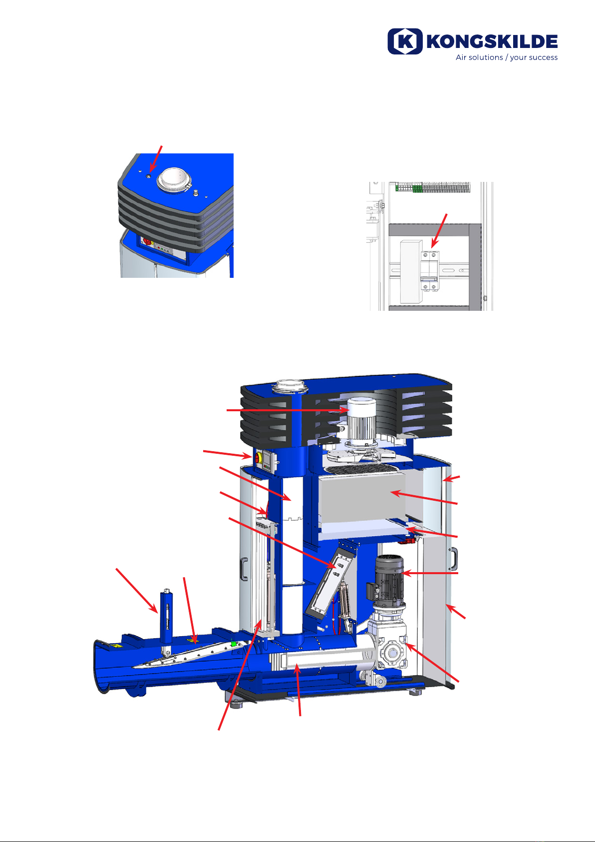
The trim handler is powered by a built-in blower that
creates the conveying air, and an electric gear motor
that creates the compression of the material via a pis-
ton.
The trim handler is designed to be easily moved using
a pallet lifter or forklift, and can easily be connected to
the piping with a quick clamp at the top of the trim han-
dler.
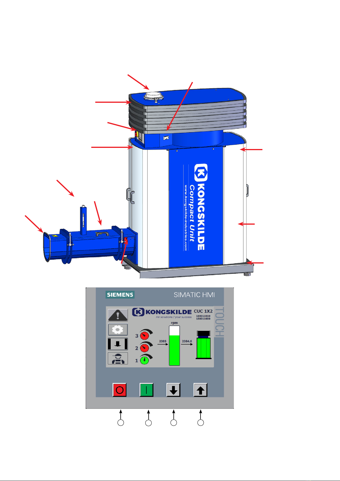
Operation of the trim handler takes place on the front,
where it can be started and stopped, blower speed
adjusted, and the status of lter changes etc. read.
The trim handler is not designed for moist, sticky or
hard materials.
Warning notes:
Avoid accidents by always following the safety regula-
tions stated in the user manual and on the trim handler.
The trim handler must be mounted in a closed pipe
system, with no access for people to moving parts.
There is a risk of damage to the trim handler if foreign
bodies of a certain size are sucked up / dropped into
the pipe system.
Lack of supervision of the trim handler can lead to wear
and tear of vital parts, see section "Service and mainte-
nance".
The installation and fastening must be carried out in
accordance with regulations (see section "Installation"),
otherwise the stability will deteriorate and the wear and
tear will increase.
Make sure all covers and doors are in place and prop-
erly secured during operation.
Always disconnect power and pressurized air to the
trim handler prior to repair and maintenance. The
main switch must be switched o and locked to en-
sure the trim handler cannot be started by mistake.
Ensure that there are safe access routes that can be
used for repair and maintenance of the trim handler.
The working area around the trim handler should be
clear and trip free so that there is no risk of falling ac-
cidents.
Ensure sucient lighting conditions for safe operation
of the trim handler.
Be careful not to tear or pinch ngers when opening the
material outlet cover.
If any abnormal vibrations or noise are observed, the
trim handler must be stopped immediately, and quali-
ed assistance must be called.
Use eye protection when working close to the air outlet
of the blower. In case of small particles in the conveyed
material, these might be blown from the air outlet of the
blower, causing eye damage.
Make sure that the trim handler stands on a stable,
level surface so that it is secured against falling and
tipping over.
Be careful not to get ngers or hands pinched when
opening or closing the doors, or the outlet lid. Also be
aware that there is a risk of pinching ngers if a hand is
put into the material outlet, in e.g. removal of blocked
material. Be aware of the risk of crushing around the
piston mechanism when the cover is removed.
Also be careful when handling the output lid, as it is
heavy.
The trim handler's blower speed can be set steplessly
using the operator panel. In order not to overload the
blower and motor, the speed cannot be set higher than
what the blower is designed for. It is not permitted to
modify the electrical equipment to increase the blower´s
maximum speed.
The trim handler is designed so that it is not possible to
come into contact with rotating parts during normal op-
eration. However, be aware that if guards are removed
and stop switches are short-circuited and the trim han-
dler is started, there is risk of personal injury.
Warning signs:
Avoid accidents by always following the safety instruc-
tions which are specied in the manual and on the
blower.
Warning labels with symbols without text are located on
the blower. The meaning of the symbols is explained
below. If a warning label gets damaged, and is no long-
er legible, it must be replaced. New labels are available
in the spare parts list.