manuals.online logo
Brands
  1. Home
  2. •
  3. Brands
  4. •
  5. Troy-Bilt
  6. •
  7. Lawn And Garden Equipment
  8. •
  9. Troy-Bilt OEM-290-257 User manual

Troy-Bilt OEM-290-257 User manual

IMPORTANT: Your new row marker is designed to attach to the Troy-Bilt Hiller-Furrower attachment. If you don’t have Hiller-
Furrower, call us or visit www.troybilt.com to place an order:
OEM-290-250 for Horse Model tillers
OEM-290-251 for Pony, Econo-Horse and Junior Model tillers
Introduction
Row Marker OEM-290-257 will help you lay out your garden with speed, accuracy and convenience — without the bother of
stakes, strings, tape measures and other tools. It’s fast and easy to assemble, mount and use with your TROY-BILT HORSE Model,
ECONO-HORSE, PONY or JUNIOR Model tiller too! Just follow these assembly & use instructions.
NOTE: If you ordered a Hiller-Furrower with your Row Marker, be sure to install the Furrower blade first, as the Row Marker
attaches directly to the Furrower blade and must be used with it. Separate assembly instructions are included with the Hiller-
Furrower. If you already had a Hiller-Furrower, just attach the Furrower blade to your TROY-BILT Tiller as always and follow the
Row Marker instructions here.
Row Marker
OEM-290-257 / 290-257-081
1 1904522 Main Support & Yoke Assembly ....... 1
2 GW-1594 Marker Blade ..................................... 1
3 1904524 Main Marker Arm .............................. 1
4 1904523 Marker Arm Extension (w/ stop pin). 1
5 GW-1837 Hardware Package (includes below) . 1
GW-9347 Hitch Pin ........................................... 1
GW-9828 Hex Nut, #10-24................................ 2
1100135 Screws, #10-24 x 1........................... 2
GW-9786 Thumb Screws, 1/4-20...................... 2
GW-1596 Nut Bar.............................................. 1
REF. PART
No. No. DESCRIPTION QTY.
TO PREVENT INJURY FROM MOVING PARTS OR HOT
SURFACES:
• Stop the engine and wait for all moving parts to
stop.
• Disconnect the spark plug wire from the spark plug
and allow the muffler to cool.
Tools Needed
• 9/16” wrench (or adjustable wrench)
• 3/8” wrench (or adjustable wrench)
• Pliers
Step 1: Attach Main Support to the Furrower
1. Using a 9/16” wrench or adjustable wrench, first
remove the two 3/8” hex nuts and lockwashers that
secure the furrower blade to its bracket.
2. Position the Row Marker Main Support on the two
3/8”-16 x 1-1 /2” long bolts (A and B in Photo 1).
Note: The Stop Bar on the Main Support faces out toward
the operator and the two bottom holes in the Main Support
are used for mounting.
3. Replace both lockwashers and hex nuts and tighten
securely.
4. Using a 9/16” wrench, remove hex nuts and lockwash-
ers from bolts “A” and “B“, install Main Support on
bolts as shown. Replace nuts and washers.
WARNING
Be sure you received all the hardware and parts listed below. If anything is missing or damaged, please write or give us a call
using the information provided on the back cover of this manual.
Contents of Carton
Step 2: Mount the Marker Blade
on the Marker Arm Extension
1. The Marker Arm Extension is the 27” long solid steel
shaft with a stop pin at one end and two mounting
holes at the other end. Place this arm on a flat surface
(table, etc.) for working ease.
2. Slide the extension arm into the “V-shape” of the blade
(see Photo 2), aligning the holes in the arm with the
holes in the blade. Be sure the stop pin at the other end
of the arm and the points of the blade are facing you.
3. Insert two #10-24 x 1” lg. round head screws through
the blade and the arm holes and secure them with two
#10-24 hex nuts (the nuts have permanently attached
star washers) as shown in Photo 3. The star washer
side of the hex nut should face the Extension Arm.
Tighten firmly with a 3/8” wrench. Use a screwdriver, if
necessary, to keep the screws from turning while the
nuts are being tightened.
Step 3: Slide Marker Arm Extension
into the Main Arm
1. With the stop pin at the end of the Extension Arm and
the holes facing you, slide the Extension Arm into the
hollow Main Arm. See Photo 4.
Note: You may push the Extension Arm in as far as you
wish for now. When completely assembled, you’ll be able
to immediately adjust to whatever widths between rows
you may want just by retracting or extending the Extension
Arm.
Photo 1
Photo 2
Photo 3
Photo 4
2. Insert the Nut Bar lengthwise into the Main Arm as
shown in Photo 5. Continue to slide the bar in until the
two tapped holes in the Nut Bar are aligned with the
two holes at the end of the Main Arm. When the holes
are aligned, and the Extension Arm is at the length you
want, then secure the arms together with two 1/4”-20 x
1/2” long thumbscrews (see Photo 6 inset) turning
them until they’re tight.
Note: To adjust the Marker Extension Arm in or out to suit
a row width for your application, simply unthread the
thumbscrews one full turn, then adjust the arm length
before retightening the thumbscrews. Fully extended, the
Row Marker is 49-3/4” long; fully retracted, 28”.
Step 4: Attach Main Marker Arm
to the Main Support
The Main Marker Arm connects to the Yoke at the top of
the Main Support with a quick-release pin.
1. Align the sleeve located at the end of the Main Arm
between either the top set or bottom set of holes on the
yoke sides. See Photo 7.
2. Once the sleeve is lined up, insert the quick release pin
(Photo 8, Inset). At this point, the Main Arm rests on
the Stop Bar and points straight back from the rear of
the tiller.
IMPORTANT: The top and bottom sets of holes on the yoke
sides allow the marker arm to rest on the Stop Bar at the
proper angle regardless of whether the Extension Arm is
fully extended or retracted. When the extension arm is
more than 50% extended, use the bottom set of holes,
otherwise use the top set of holes.
3. Pivot the Marker Arm from its “straight back” position a
full 90°to either the right or the left in order to get the
Marker Arm to point out to the side of the Tiller.
Whether you decide to pivot right or left, just be sure
the points of the Marker Blade face back toward the
operator after the arm has been pivoted. See Photo 9
and Photo 10 for the correct in-use position.
Photo 7 & Photo 8 (inset)
Photo 9
Photo 5 & Photo 6 (inset)
Photo 10
NOTE: the points of the Marker Blade must be facing back
toward the operator, not toward the front of the Tiller.
Practice Pivoting The Row Marker Arm
Start with the arm on the left side (see Photo 11), then just
lift up and swing it over to the right side (Photo 12).
IMPORTANT: Before turning your Tiller, always lift up on
the handlebars to raise the Marker Blade out of the soil to
avoid damaging it.
IMPORTANT: Never put the tiller in reverse unless the
Marker Blade is out of the soil; damage could result.
NOTE: When using The Row Marker with your PONY,
ECONO-HORSE, or JUNIOR Tiller, be sure the handlebar
height is adjusted to one of the three highest settings so
the Marker Arm has sufficient clearance to swing past the
handlebar grips.
To Make Raised Beds . . . Add the Hiller Wings
Add the Hiller Wings to your Furrower Blade and you’ll be
able to mark out and make raised rows (beds) at the same
time. Photo 13 shows the complete Hiller/Furrower with
Row Marker attached on the Horse Model Tiller. See last
page for raised bed instructions. Mount the Hiller Wings
and you’re ready to make wide-row, raised beds.
How To Use Your Row Marker...
Before using your Row Marker, remember the following:
1. All nuts and bolts (and the thumbscrews) should be
tight on the Row Marker and Hiller/Furrower attach-
ments.
2. Don’t put the tiller in reverse unless the marker blade is
raised up off the ground.
3. Lift up on the tiller handlebars before making a turn to
prevent Row Marker damage.
4. If you accidentally hit an obstruction causing the mark-
er arm to shift out of alignment, adjust the arm back to
its original position before continuing (remember, the
arm forms a perfect right angle with the Main Support
when it’s adjusted properly). See Back Cover for how to
adjust the tension on the Yoke Assembly.
General Use for Deep Furrows
1. Prepare a good seedbed with your tiller.
2. Adjust the marker length for the spacing you want
between rows for planting and cultivation.
3. Start with your tiller on the edge of your garden where
you want your first furrow.
4. Place the Row Marker arm on the side where the sec-
ond furrow will be.
5. Proceed to make the furrow as you normally would,
walking in the furrow directly behind your tiller, using
both hands.
6. To get the first furrow straight, pick out a distant object
in line with your row. Then, look straight ahead and aim
toward it. The quicker you make the furrow (high
speed, open throttle) the straighter the furrow and row
marker guideline will be.
7. At the end of the first row, lift up on the handlebars,
turn the tiller around, and center your tiller on the Row
Marker guideline you just made.
Photo 11 & Photo 12
Pivot the Row Marker arm over to the other side of
your tiller, and start in on the second row, sighting
straight ahead down the guideline.
Tip: When planting different types of seeds or transplants
in the new row, make the necessary adjustment in the
depth of the Furrower before starting the new row.
Shallow Furrows For Small Seeds or to Mark Row
Positions
• Put your depth regulator in the second or third notch
and use the Row Marker as before, only walk beside the
tiller and run one wheel right on the guideline mark
rather than centering the guideline between the wheels.
(It will be easier to see and follow the line.)
• For best results, use the tiller at a higher speed .
• Mark out your entire garden with 1”-2” deep furrows.
That way the position of all your rows will be clear from
the beginning and you can start planting anywhere
you’d like. Or, you can go over any of these rows later
to make a deeper furrow, or tiller swath for wide-row
planting. Just follow the Row Marker guidelines.
Deep Furrows For Fertilizing or Trench Cornposting
• Mark out all your rows with 6”-8” furrows, using the
Row Marker as described for making deep furrows
under General Use. Now you can fill in these deep fur-
rows with compost or manure (plus a covering of soil)
and plant right on top. This method concentrates all the
nutrients where the plants need them and does not
waste them in the walkways.
Raised Beds
• To help make raised beds, set the Row Marker arm to
between 40” and 49-3/4” long and add the Hiller Wings
to your furrower. Make several passes with the Hiller/
Furrower-Row Marker, as described in General Use. The
wings throw up ridges between furrows. Level off the
ridges with a rake and you’ll have raised beds all ready
to plant. Add Hiller Wings for raised beds.
IMPORTANT: Check and Adjust the Tension Setting on the
Yoke Assembly regularly. The Yoke Assembly on the Main
Support has been factory tightened to allow the Yoke to
pivot when the Marker Blade meets a certain amount of
resistance. This prevents damage to the Row Marker com-
ponents. If the setting should ever loosen, you should
retighten the hex nut on the Yoke
Assembly as tight as possible.
• Use a 9/16” socket or box end wrench to tighten the
nut with one hand, and use the other hand on the Row
Marker arm to steady the Yoke and keep it from pivot-
ing. Turn nut counter-clockwise.
Photo 13
Photo 14
Photo 15
NOTES
NOTES
For customer assistance, visit www.troybilt.com, contact your nearest authorized dealer or:
TROY-BILT LLC, P.O. BOX 361131, CLEVELAND, OHIO 44136-0019, 1-866-840-6483
Printed in U.S.A. Form 769-00135 (04/2002)

This manual suits for next models

1

Other Troy-Bilt Lawn And Garden Equipment manuals
Troy-Bilt TB25GHT User manual

Troy-Bilt

Troy-Bilt TB25GHT User manual

Troy-Bilt TB 672 User manual

Troy-Bilt

Troy-Bilt TB 672 User manual

Troy-Bilt OEM-290-254 User manual

Troy-Bilt

Troy-Bilt OEM-290-254 User manual

Troy-Bilt TB4HB User manual

Troy-Bilt

Troy-Bilt TB4HB User manual

Troy-Bilt OEM-290-256 User manual

Troy-Bilt

Troy-Bilt OEM-290-256 User manual

Troy-Bilt JUNIOR User manual

Troy-Bilt

Troy-Bilt JUNIOR User manual

Troy-Bilt Colt FT User manual

Troy-Bilt

Troy-Bilt Colt FT User manual

Troy-Bilt TB154E User manual

Troy-Bilt

Troy-Bilt TB154E User manual

Troy-Bilt TB2044 User manual

Troy-Bilt

Troy-Bilt TB2044 User manual

Troy-Bilt TB146 User manual

Troy-Bilt

Troy-Bilt TB146 User manual

Troy-Bilt TB146 EC User manual

Troy-Bilt

Troy-Bilt TB146 EC User manual

Troy-Bilt CSV 206 User manual

Troy-Bilt

Troy-Bilt CSV 206 User manual

Troy-Bilt TB225 User manual

Troy-Bilt

Troy-Bilt TB225 User manual

Troy-Bilt CS4265 User manual

Troy-Bilt

Troy-Bilt CS4265 User manual

Troy-Bilt Bronco CRT User manual

Troy-Bilt

Troy-Bilt Bronco CRT User manual
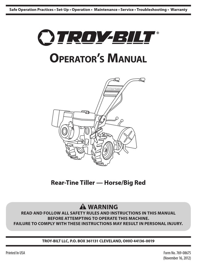
Troy-Bilt Big Red User manual

Troy-Bilt

Troy-Bilt Big Red User manual

Troy-Bilt Big Red User manual

Troy-Bilt

Troy-Bilt Big Red User manual

Troy-Bilt TB42 Hydro User manual

Troy-Bilt

Troy-Bilt TB42 Hydro User manual

Troy-Bilt Horse Tiller User manual

Troy-Bilt

Troy-Bilt Horse Tiller User manual

Troy-Bilt TB180B User manual

Troy-Bilt

Troy-Bilt TB180B User manual

Troy-Bilt CS4325 Series User manual

Troy-Bilt

Troy-Bilt CS4325 Series User manual
Troy-Bilt Bronco CRT User manual

Troy-Bilt

Troy-Bilt Bronco CRT User manual

Troy-Bilt TBBT User manual

Troy-Bilt

Troy-Bilt TBBT User manual

Popular Lawn And Garden Equipment manuals by other brands

DIG G77AS installation instructions

DIG

DIG G77AS installation instructions

BorMann Home Bik3000 owner's manual

BorMann

BorMann Home Bik3000 owner's manual

Caddon Hives WBC Assembly instructions

Caddon Hives

Caddon Hives WBC Assembly instructions

caron 7310-22 Operation manual

caron

caron 7310-22 Operation manual

Ducati DEA 5200 owner's manual

Ducati

Ducati DEA 5200 owner's manual

Briggs & Stratton Amplifi Hose Powering System Quick setup guide

Briggs & Stratton

Briggs & Stratton Amplifi Hose Powering System Quick setup guide

Makisolar DR-0433-G instruction manual

Makisolar

Makisolar DR-0433-G instruction manual

RUSTA 624013440101 manual

RUSTA

RUSTA 624013440101 manual

Perel GIK36N user manual

Perel

Perel GIK36N user manual

Textron JACOBSEN Eclipse 118F Technical/repair manual

Textron

Textron JACOBSEN Eclipse 118F Technical/repair manual

Agri-Fab 45-02942-131 owner's manual

Agri-Fab

Agri-Fab 45-02942-131 owner's manual

Classen CA-18H Operator's manual

Classen

Classen CA-18H Operator's manual

Billy Goat MV650H PUSH owner's manual

Billy Goat

Billy Goat MV650H PUSH owner's manual

International Harvester Company International 1 Operator's manual

International Harvester Company

International Harvester Company International 1 Operator's manual

Swisher ACR-500, ACR-500S owner's manual

Swisher

Swisher ACR-500, ACR-500S owner's manual

Stihl 46 instruction manual

Stihl

Stihl 46 instruction manual

Grouw! 18127 instruction manual

Grouw!

Grouw! 18127 instruction manual

Gardenline GH18N user manual

Gardenline

Gardenline GH18N user manual

manuals.online logo
manuals.online logoBrands
  • About & Mission
  • Contact us
  • Privacy Policy
  • Terms and Conditions

Copyright 2025 Manuals.Online. All Rights Reserved.