TCGG truemfg.com
TEC_TM_122 | REV. B | EN03/2/2023Page 4 of 18 P#975548
Installation
Ownership
To ensure that your unit works properly from the first day, it must
be installed properly. We highly recommend a trained refrigeration
mechanic and electrician install your TRUE equipment. The cost of
a professional installation is money well spent.
Before you start to install your TRUE unit, carefully inspect it for
freight damage. If damage is discovered, immediately file a claim
with the delivery freight carrier.
TRUE is not responsible for damage incurred during shipment.
Cabinet Location
• For proper operation, ambient temperatures shall not be less
than 60°F (15.5°C) and no greater than 104°F (40°C).
• Appliance is not suitable for outdoor use.
• Appliance is not suitable for an area where a pressure washer or
hose may be used.
• Ensure the location will provide adequate clearances and
sufficient airflow for the cabinet.
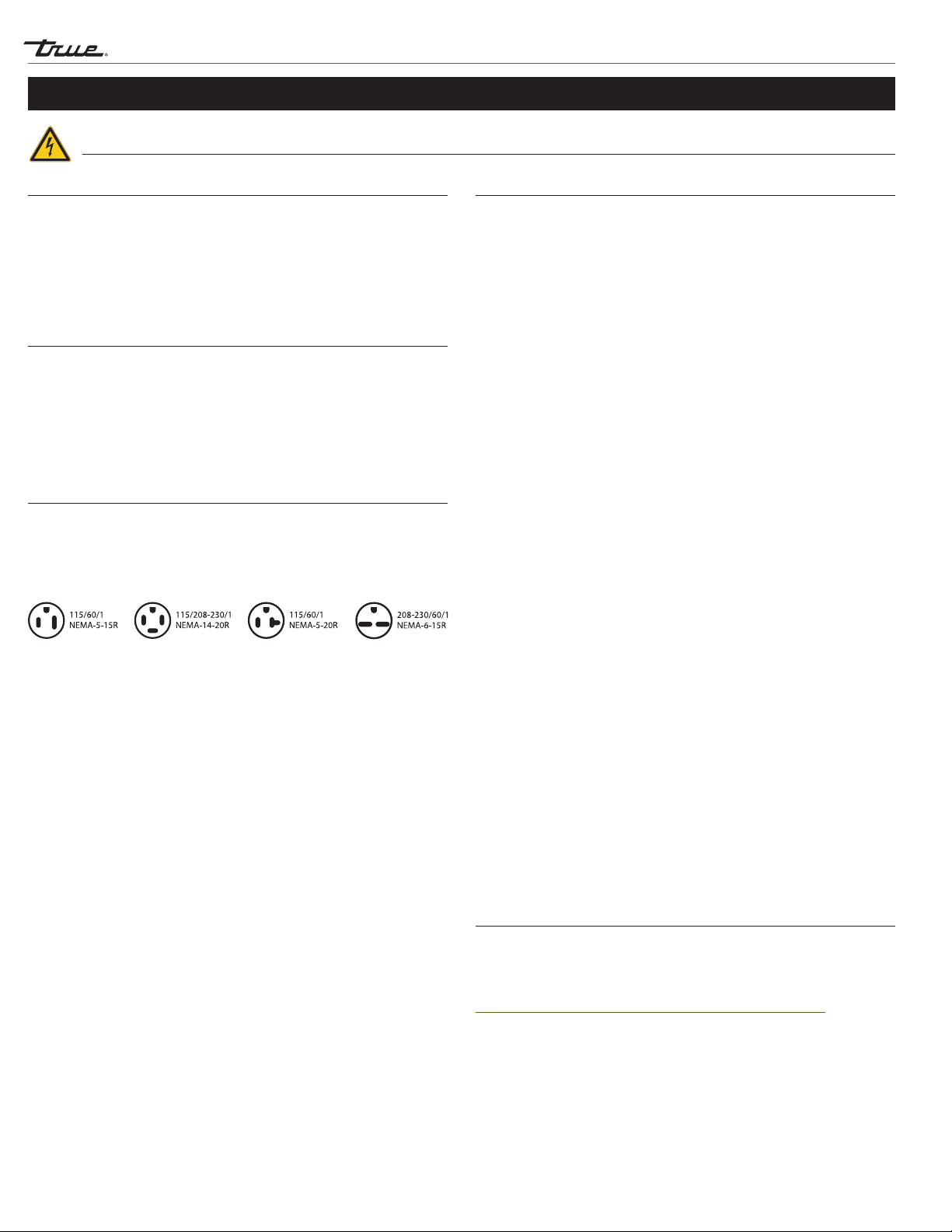
• Ensure the power supply for the cabinet matches the cabinet
specification sheet or cabinet data plate and is within the
rated voltage (+/-5%). Also, that the amp rating of the circuit is
correct and that it is properly grounded.
• The cabinet should always be plugged into its own individual
dedicated electrical circuit. The use of adapter plugs and
extension cords is prohibited.
Notice to Customer
Loss or spoilage of products in your
refrigerator/freezer is not covered by
warranty. In addition to following
recommended installation procedures, you
must run the refrigerator/freezer for 24 hours
prior to usage to verify its proper operation.
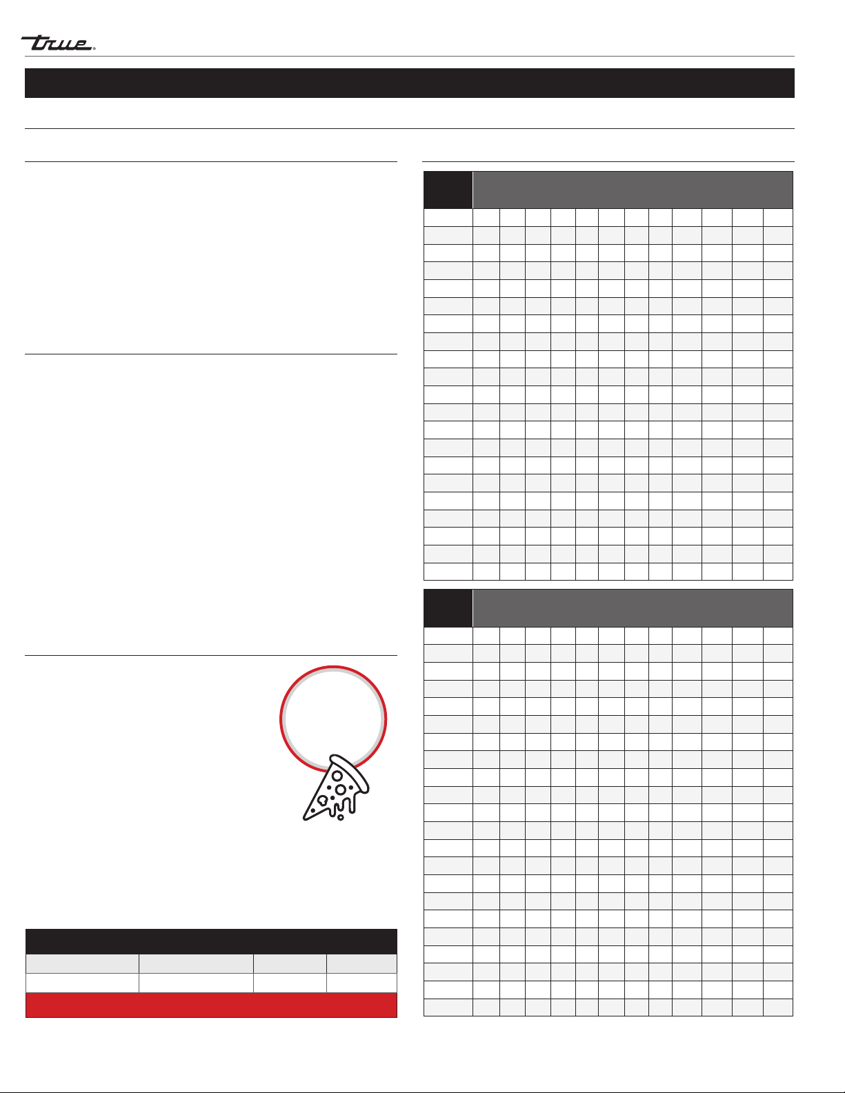
115
Volts Distance In Feet To Center of Load
AMPS 20 30 40 50 60 70 80 90 100 120 140 160
2 14 14 14 14 14 14 14 14 14 14 14 14
3 14 14 14 14 14 14 14 14 14 14 14 12
4 14 14 14 14 14 14 14 14 14 12 12 12
5 14 14 14 14 14 14 14 12 12 12 10 10
6 14 14 14 14 14 14 12 12 12 10 10 10
7 14 14 14 14 14 12 12 12 10 10 10 8
8 14 14 14 14 12 12 12 10 10 10 8 8
9 14 14 14 12 12 12 10 10 10 8 8 8
10 14 14 14 12 12 10 10 10 10 8 8 8
12 14 14 12 12 10 10 10 8 8 8 8 6
14 14 14 12 10 10 10 8 8 8 6 6 6
16 14 12 12 10 10 8 8 8 8 6 6 6
18 14 12 10 10 8 8 8 8 8 8 8 5
20 14 12 10 10 8 8 8 6 6 6 5 5
25 12 10 10 8 8 6 6 6 6 5 4 4
30 12 10 8 8 6 6 6 6 5 4 4 3
35 10 10 8 6 6 6 5 5 4 4 3 2
40 10 8 8 6 6 5 5 4 4 3 2 2
45 10 8 6 6 6 5 4 4 3 3 2 1
50 10 8 6 6 5 4 4 3 3 2 1 1
230
Volts Distance In Feet To Center of Load
AMPS 20 30 40 50 60 70 80 90 100 120 140 160
5 14 14 14 14 14 14 14 14 14 14 14 14
6 14 14 14 14 14 14 14 14 14 14 14 12
7 14 14 14 14 14 14 14 14 14 14 12 12
8 14 14 14 14 14 14 14 14 14 12 12 12
9 14 14 14 14 14 14 14 14 12 12 12 10
10 14 14 14 14 14 14 14 12 12 12 10 10
12 14 14 14 14 14 14 12 12 12 10 10 10
14 14 14 14 14 14 12 12 12 10 10 10 8
16 14 14 14 14 12 12 12 10 10 10 8 8
18 14 14 14 12 12 12 10 10 10 8 8 8
20 14 14 14 12 10 10 10 10 10 8 8 8
25 14 14 12 12 10 10 10 10 8 8 6 6
30 14 12 12 10 10 10 8 8 8 6 6 6
35 14 12 10 10 10 8 8 8 8 6 6 5
40 14 12 10 10 8 8 8 6 6 6 5 5
50 12 10 10 8 6 6 6 6 6 5 4 4
60 12 10 8 6 6 6 6 6 5 4 4 3
70 10 10 8 6 6 6 5 5 4 4 2 2
80 10 8 8 6 6 5 5 4 4 3 2 2
90 10 8 6 6 5 5 4 4 3 3 1 1
100 10 8 6 6 5 4 4 3 3 2 1 1
Wire Gauge Chart
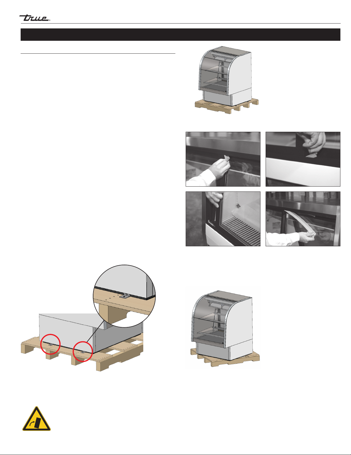
Prior to Installation
CLEARANCES
TOP SIDES BACK
TCGG 0" 0" Open
WARNING – Warranty is void if ventilation is insufficient.